P0344 and P0349 error codes - No CEL
 11-23-2015, 03:44 PM
#1
Intermediate
Thread Starter
Join Date: Jun 2007
Location: Bay Area, CA
Posts: 40
Likes: 0
Received 0 Likes
on
0 Posts
Looking for some help with this one . . .
I have a 2002 996 (ME7.8 I believe) which appears to run perfectly normally (a very slight 'hiccup' in the 1800 to 2000 rpm range noticeable especially when the engine is cold) with no CEL. However, plugging in the Durametric I am seeing two camshaft sensor faults;
P0344 � Porsche Fault Code 112 Phase Sensor 1 (Camshaft Hall Effect Sensor 1)
P0349 � Porsche Fault Code 113 Phase Sensor 2 (Camshaft Hall Effect Sensor 2)
I have replaced both cam sensors � no difference. I have verified the connections and have 12v feed and good ground on both sensors. Both sensors appear to be putting out a signal based on what I can see in Durametric.
Plotting actual values on the Durametric show I have consistent cam deviations in the 0.3 to 1.5 range with the value for each bank being very close to the other. Is this enough to assume the cam timing is correct? I also believe the variable cam timing to be functioning as I have plotted spec angle against actual and the traces track each other well (further verified by the consistent camshaft deviation I am assuming?).
Here�s where it gets interesting � If I clear the codes with the engine at idle, I can leave the engine idling without the codes coming back. If I clear the codes while the car is driving, I can vary engine speed without the codes coming back. The codes come back as the engine speed transitions from running range to idle range.
I have some theories, but does anyone have any insight they could share? Any actual experience of the same or similar issues?
Thanks in advance.
 11-23-2015, 03:59 PM
#2
Has the engine ever been rebuilt or work been done on the heads/camshafts? The cam reluctor wheels may be bent but on both banks though?
The reason the code is not tripped during idle is probably because the pre-condition of the test for these codes is not met.
The reason the code is not tripped during idle is probably because the pre-condition of the test for these codes is not met.
11-23-2015, 04:25 PM
#3
Intermediate
Thread Starter
Join Date: Jun 2007
Location: Bay Area, CA
Posts: 40
Likes: 0
Received 0 Likes
on
0 Posts
Ahsai - Yes the engine was completely rebuilt 18 months ago. I understand the thinking behind the reluctor wheel being bent, but I must be getting a signal from both sensors as the Durametric is able to read my cam position - correct? Also, as you state, to have what appears to be the same issue on both banks seems unlikely.
Could someone please tell me how the reluctor wheel is mounted on the camshaft? Any good photos anywhere? Is it possible to mount it incorrectly?
I won't rule it our completely, but it didn't seem to be a logical explanation.
Could someone please tell me how the reluctor wheel is mounted on the camshaft? Any good photos anywhere? Is it possible to mount it incorrectly?
I won't rule it our completely, but it didn't seem to be a logical explanation.
11-23-2015, 04:59 PM
#4
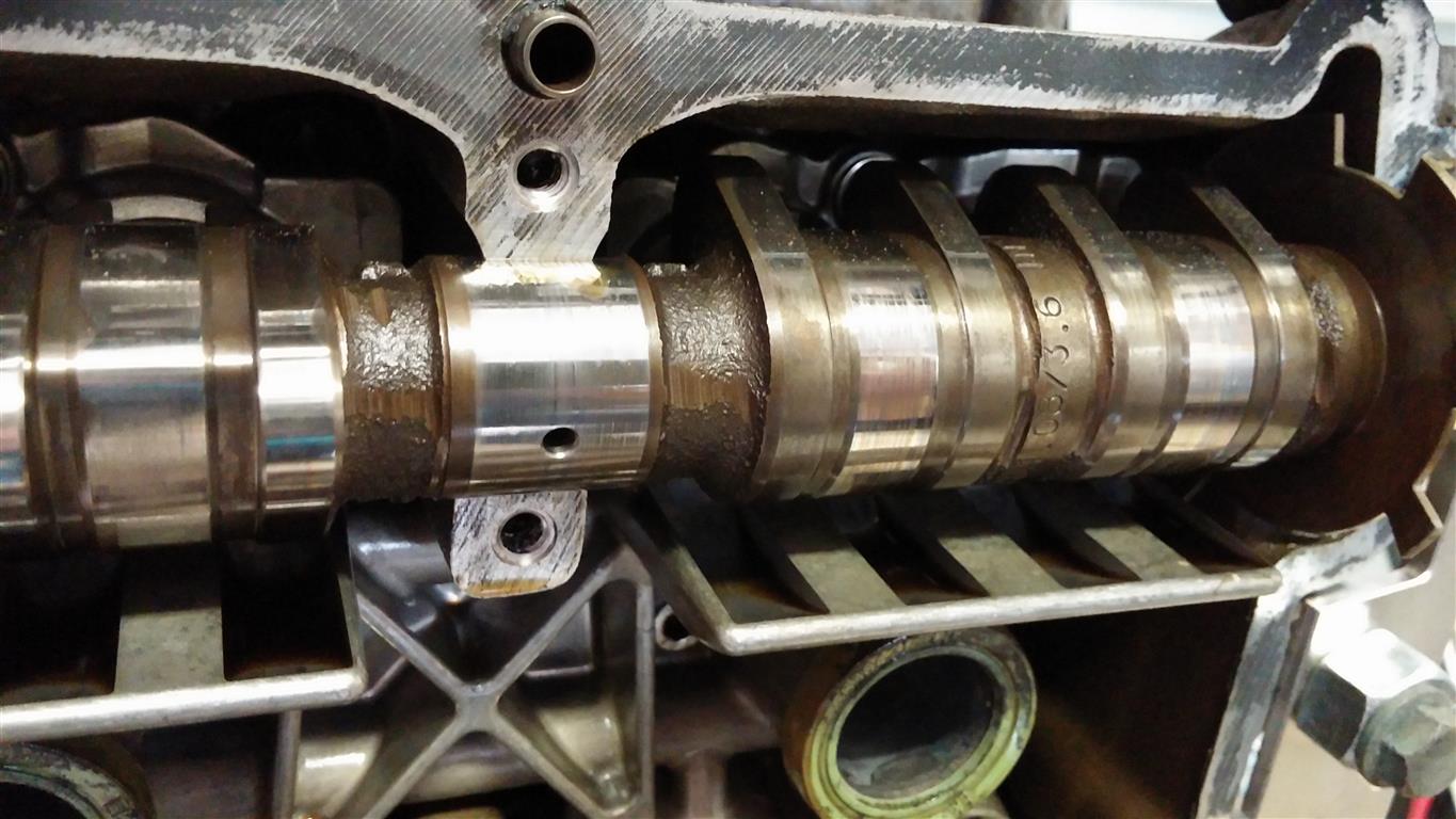
Here's a photo on the reluctor on an '02 engine (bank 1 intake). Looks like it's part of the camshaft as one piece but not 100% sure.
I agree that your steady cam deviation and correct timing indicate the reluctors must be working to some degree. However, the DME may still be able to tolerate some abnormality. Interesting problem and I think one will need to use an oscilloscope to check the actual cam sensor signals to see what's going on, especially when the engine decelerates. If you see signal drop out, that would give you more clues. The other thinking is when the engine decelerates, maybe there's something shifting in the timing chains? Are oil pressure good and the tensioners good?
I agree that your steady cam deviation and correct timing indicate the reluctors must be working to some degree. However, the DME may still be able to tolerate some abnormality. Interesting problem and I think one will need to use an oscilloscope to check the actual cam sensor signals to see what's going on, especially when the engine decelerates. If you see signal drop out, that would give you more clues. The other thinking is when the engine decelerates, maybe there's something shifting in the timing chains? Are oil pressure good and the tensioners good?
11-23-2015, 05:13 PM
#5
Rennlist Member
Join Date: Apr 2010
Location: Ormond Beach, FL
Posts: 5,811
Likes: 0
Received 1,091 Likes
on
701 Posts
I was just wondering...maybe the point of commonality is between the camshaft sensors and the crankshaft position sensor. Have you checked the crankshaft position sensor? It seems highly improbable that both camshaft hall effect sensors could be installed wrong or faulty. Since you have replaced both that pretty much rules out a faulty unit. But the DME compares the signals from the camshaft sensors with the crankshaft position sensor to determine where everything is. Faulty CPS?
The following users liked this post:
ca2014mp2 (06-01-2022)
11-23-2015, 05:25 PM
#6
Intermediate
Thread Starter
Join Date: Jun 2007
Location: Bay Area, CA
Posts: 40
Likes: 0
Received 0 Likes
on
0 Posts
Thank you for your thoughts on this. I appreciate someone else thinking about this and sharing ideas.
It's difficult to see exactly how the reluctor is fitted. Although it looks to be part of the camshaft it's such a thin piece of material I wouldn't have thought it would be machined like that from the casting/forging. Still, it doesn't look movable short of bending it. Maybe I can remove the sensor and rotate the engine by hand. I could visually check to verify the reluctor is in the right place and not bent. Other than that the oscilloscope may be the best bet.
Regarding the chain tensioners, all the chain guides and tensioner pads were replaced in the rebuild. However, one of the things on my mental list is to pull the tensioners and make sure everything looks to be working correctly there. Incidentally, oil pressure is great - high and stable.
As I say, generally everything runs fine, but it's this one little glitch has me scratching my head.
11-23-2015, 05:44 PM
#7
Intermediate
Thread Starter
Join Date: Jun 2007
Location: Bay Area, CA
Posts: 40
Likes: 0
Received 0 Likes
on
0 Posts
I agree, it seems highly improbable that BOTH camshaft sensors are faulty. Not just both the old ones, but both the new ones. That was why I checked all the common harness feeds to verify there were no shorts and I had continuity. I suppose it could be the crank position, but I would expect to be having significant issues if that were the case. Also, the diagnostic capability is fairly advanced, so why would it not show a crankshaft position fault? Not trying to dismiss your suggestion, but that is my line of thinking.
I do wonder what types of things will trigger an error in the DME. Does it need the signal to drop out? Is it smart enough to fault out if it suddenly gets a value, or string of values, which don't align to what it expects?
I do wonder what types of things will trigger an error in the DME. Does it need the signal to drop out? Is it smart enough to fault out if it suddenly gets a value, or string of values, which don't align to what it expects?
Trending Topics
11-23-2015, 06:12 PM
#8
Joe,the crank sensor also crossed my mind but I also ranked it as low probability like the same reasons the OP mentioned.
Aerkuld, I don't know the exact algorithm in the cam fault detection but I can tell you there are 4 diff cam related codes per the factory diagnostic manual (bank 1 shown):
P0341 - signal implausible (possible cause: loose connection)
P0342 - signal below limit (possible cause: short to ground)
P0343 - signal over limit (possible cause: short to +12v)
P0344 - open circuit (possible cause: camshaft rotor damaged)
Also, pre-condition of P0344 requires no errors with P0341, 0342, and 0343. So with P0344, its likely the issue is not due to wire/connection but more like the basic wave form the DME expects hence my suggestion of using an oscilloscope.
11-23-2015, 06:24 PM
#9
Intermediate
Thread Starter
Join Date: Jun 2007
Location: Bay Area, CA
Posts: 40
Likes: 0
Received 0 Likes
on
0 Posts
Interesting - That information is a great help. It may be later this week, but I'll try hooking up the 'scope and also see if there are any visual inconsistencies if I pull the cam sensors and peer in the hole.
Any more in depth information about the Porsche Fault Code 112 and 113? Are they just Porsche's version of the generic OBDII codes P0344 and P0349, or do they have more significance?
Also, what is the significance of this generating a fault code, but not illuminating the CEL? Is it indicating it's not a serious fault, or intermittent fault , or am I reading too much into it?
If anyone has any other ideas I'm more than happy to hear them.
Thanks again.
Last edited by Aerkuld6; 11-23-2015 at 06:47 PM.
11-23-2015, 10:05 PM
#10
112 and 113 are just Porsche versions of the P0344 and P0349, respectively.
Some faults will need to occur persistently before the CEL is tripped. Maybe you have an intermittent problem.
I just checked the wiring diagram and found that actually the two sensors share two common feeds - the +5v sensor reference and the ground, both coming from the DME via the x59/2 plug on pin 21 and 22. Sometimes when an engine is removed and waiting for rebuild, those pins are exposed to the element and get corroded. I recommend you disconnect the x59/2 plug and visually check for corrosion on those pins. Then spray some Deoxit on the pins. Also check the DME plug C (III) pins 7 and 17 and reseat the plug. Then reset the codes and retest.
The following users liked this post:
ca2014mp2 (06-01-2022)
11-24-2015, 08:57 AM
#11
Rennlist Member
Join Date: Apr 2010
Location: Ormond Beach, FL
Posts: 5,811
Likes: 0
Received 1,091 Likes
on
701 Posts
I agree Ahsai. I was throwing that in from memory but did not have much time yesterday to research. I did see that P0344 and P0349 are "intermittent" signals from the camshaft hall effect sensors, not total failure. I believe you are on the right track regarding the common feeds and ground pin connectors, as well as the DME connectors. Also, OP - any sign of water under the seats? Or previous water damage? I would also suggest to the OP to disconnect and clean the engine ground strap. When you Google the error codes, a lot of good suggestions pop up on the intermittent nature of the signals from the sensors and how to check the voltage. Almost all modern engines use these types of camshaft sensors. But the only true way to check them is with an Oscilloscope and the return wave form. If you can find a way to do that it would beat dissecting the engine in case it is something less complex.
11-24-2015, 01:45 PM
#13
Intermediate
Thread Starter
Join Date: Jun 2007
Location: Bay Area, CA
Posts: 40
Likes: 0
Received 0 Likes
on
0 Posts
Thank you again for the help. I suspect you’re both correct that this is an intermittent problem. I will see if I can get the oscilloscope hooked up later this week and check the output of the sensors. I’m not sure how difficult it will be to find this if it is a problem which occurs in an instant, then returns to normal, but will give it a go.
DBJoe has some good suggestions too – I have cleaned all the grounds (I had an old 944 so learned that trick fast), and battery positive connections. There is no water under the seats, or in the back seat area where the DME resides. No previous water damage either. Good suggestions though and I appreciate your input as I may well have missed something. As you point out, a problem on BOTH sensors would tend to indicate a common feed, so this was one of my first thoughts.
I have checked the harness between both sensors, the sensors and pin 21 on the X59/2 plug, pin 21 on the X59/2 plug and the DME pin c17, then the sensors all the way through to the DME. I am showing a good ground with less than 0.5 ohms. Connector is clean with no corrosion to speak of. I think I’ll give it a blast with some Deoxit regardless. I am interested in the voltage though . . .
I am seeing 12v supplied to the sensors, not 5v. I agree, the wiring diagram does show DME pin c7 as +5v supply. Not to doubt your knowledge Ahsai, but do they mean it’s the supply for the +5V signal, or do they mean it’s actually a 5v supply? I know the output from hall-effect sensors is a 5v square wave, and there are a lot of other engine sensors which use a 5v reference output. However, most hall-effect sensors call for a supply voltage between 4v and 18v. This Bosch sensor (http://www.bosch-motorsport.com/medi...1851403pdf.pdf) asks for a 4.5 to 24v input for example. If that’s the case, the hall-effect sensors should be producing a signal either way, but maybe the signal voltage is too high. Isn’t that a different fault though?
Is there any way someone could verify the sensor supply voltage by taking a measurement on another car? Is it REALLY supposed to be a 5v supply? If so, then I need to check the supply voltage harness for a short to 12v positive. If I don’t have that, then I may have an internal fault in the DME. I’d like confirmation of exactly what voltage I’m looking for before I start that if possible.
11-24-2015, 02:34 PM
#14
Good question on pin C7. I'm not sure either as I've never measured that specific pin.
If you hook up a scope, it's best to first back probe the DME connectors (as opposed to probing the sensors directly) since that will tell you what the DME sees so it will cover both sensor and wiring issues. If you see signal drop out/abnormality though, then you can probe the sensors directly and see if that's the source (sensor or bad reluctor) or it's the wires in between.
If you hook up a scope, it's best to first back probe the DME connectors (as opposed to probing the sensors directly) since that will tell you what the DME sees so it will cover both sensor and wiring issues. If you see signal drop out/abnormality though, then you can probe the sensors directly and see if that's the source (sensor or bad reluctor) or it's the wires in between.
Thank you again for the help. I suspect you�re both correct that this is an intermittent problem. I will see if I can get the oscilloscope hooked up later this week and check the output of the sensors. I�m not sure how difficult it will be to find this if it is a problem which occurs in an instant, then returns to normal, but will give it a go.
DBJoe has some good suggestions too � I have cleaned all the grounds (I had an old 944 so learned that trick fast), and battery positive connections. There is no water under the seats, or in the back seat area where the DME resides. No previous water damage either. Good suggestions though and I appreciate your input as I may well have missed something. As you point out, a problem on BOTH sensors would tend to indicate a common feed, so this was one of my first thoughts.
I have checked the harness between both sensors, the sensors and pin 21 on the X59/2 plug, pin 21 on the X59/2 plug and the DME pin c17, then the sensors all the way through to the DME. I am showing a good ground with less than 0.5 ohms. Connector is clean with no corrosion to speak of. I think I�ll give it a blast with some Deoxit regardless. I am interested in the voltage though . . .
I am seeing 12v supplied to the sensors, not 5v. I agree, the wiring diagram does show DME pin c7 as +5v supply. Not to doubt your knowledge Ahsai, but do they mean it�s the supply for the +5V signal, or do they mean it�s actually a 5v supply? I know the output from hall-effect sensors is a 5v square wave, and there are a lot of other engine sensors which use a 5v reference output. However, most hall-effect sensors call for a supply voltage between 4v and 18v. This Bosch sensor (http://www.bosch-motorsport.com/medi...1851403pdf.pdf) asks for a 4.5 to 24v input for example. If that�s the case, the hall-effect sensors should be producing a signal either way, but maybe the signal voltage is too high. Isn�t that a different fault though?
Is there any way someone could verify the sensor supply voltage by taking a measurement on another car? Is it REALLY supposed to be a 5v supply? If so, then I need to check the supply voltage harness for a short to 12v positive. If I don�t have that, then I may have an internal fault in the DME. I�d like confirmation of exactly what voltage I�m looking for before I start that if possible.
11-24-2015, 03:15 PM
#15
Rennlist Member
Join Date: Apr 2010
Location: Ormond Beach, FL
Posts: 5,811
Likes: 0
Received 1,091 Likes
on
701 Posts
From my research there are three wires to the CPS (camshaft): ground, 12V supply and a 5V reference signal created by the hall effect sensor when the camshaft is turning that is fed back to the DME (created by the reluctor and CPS magnetic sensor).
Have you unplugged, cleaned and re-attached the engine wiring harness plugs?
Have you unplugged, cleaned and re-attached the engine wiring harness plugs?