Switch led lamp resistor size
 05-15-2014, 04:45 PM
#1
Burning Brakes
Thread Starter
I am putting in a combined OBC switch and spoiler deployed indicator and am having some difficulty in testing the switch I am hoping to use. Its a window defroster switch (996.613.134.00) . I hope someone can answer a few questions.
1) Are all the dash switches wired the same, that is two intermittent switches combined with an LED and a night light?
2) Is a resistor built into the switches in line with the LED (pin 5) , or do I need to add an external one
3) If I need a resistor, what size?
Also, on my particular switch, I briefly tried putting 12 volts across the LED (using a power supply) and I cant seem to get it to light up. Its a used switch so I suppose the LED could be shot but the switch looks to be in almost new shape.
Any help is greatly appreciated.
 05-15-2014, 05:12 PM
#2
I am putting in a combined OBC switch and spoiler deployed indicator and am having some difficulty in testing the switch I am hoping to use. Its a window defroster switch (996.613.134.00) . I hope someone can answer a few questions.
1) Are all the dash switches wired the same, that is two intermittent switches combined with an LED and a night light?
2) Is a resistor built into the switches in line with the LED (pin 5) , or do I need to add an external one
3) If I need a resistor, what size?
Also, on my particular switch, I briefly tried putting 12 volts across the LED (using a power supply) and I cant seem to get it to light up. Its a used switch so I suppose the LED could be shot but the switch looks to be in almost new shape.
Any help is greatly appreciated.
1) Are all the dash switches wired the same, that is two intermittent switches combined with an LED and a night light?
2) Is a resistor built into the switches in line with the LED (pin 5) , or do I need to add an external one
3) If I need a resistor, what size?
Also, on my particular switch, I briefly tried putting 12 volts across the LED (using a power supply) and I cant seem to get it to light up. Its a used switch so I suppose the LED could be shot but the switch looks to be in almost new shape.
Any help is greatly appreciated.
2) Resistor is built in
LED needs correct polarity, try to reverse the + and - and see if it lights up. Try ground on pin 3.
05-15-2014, 05:23 PM
#3
Burning Brakes
Thread Starter
Thank you Ahsai! That did the trick. I reversed the polarity so that Pin 5 was ground and Pin 4 ( the one in the center) had + and it lit up.
Do they all have some sort of Night light built in? Pin 3 does not seem to do anything.
Hmmmm. It seems like my plan to use one switch for both the OBC and the spoiler indicator is not going to work. The OBC hack needs to take the OBC control lines to Ground on pin 4 while the LED needs to have + on the same pin (4).
05-15-2014, 05:32 PM
#4

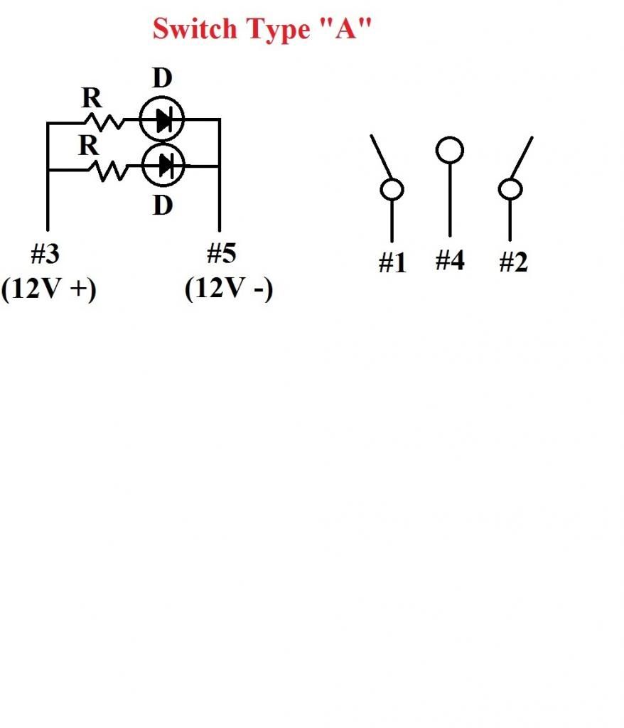
They are not at all the same. There are three types labeled A, B and C.
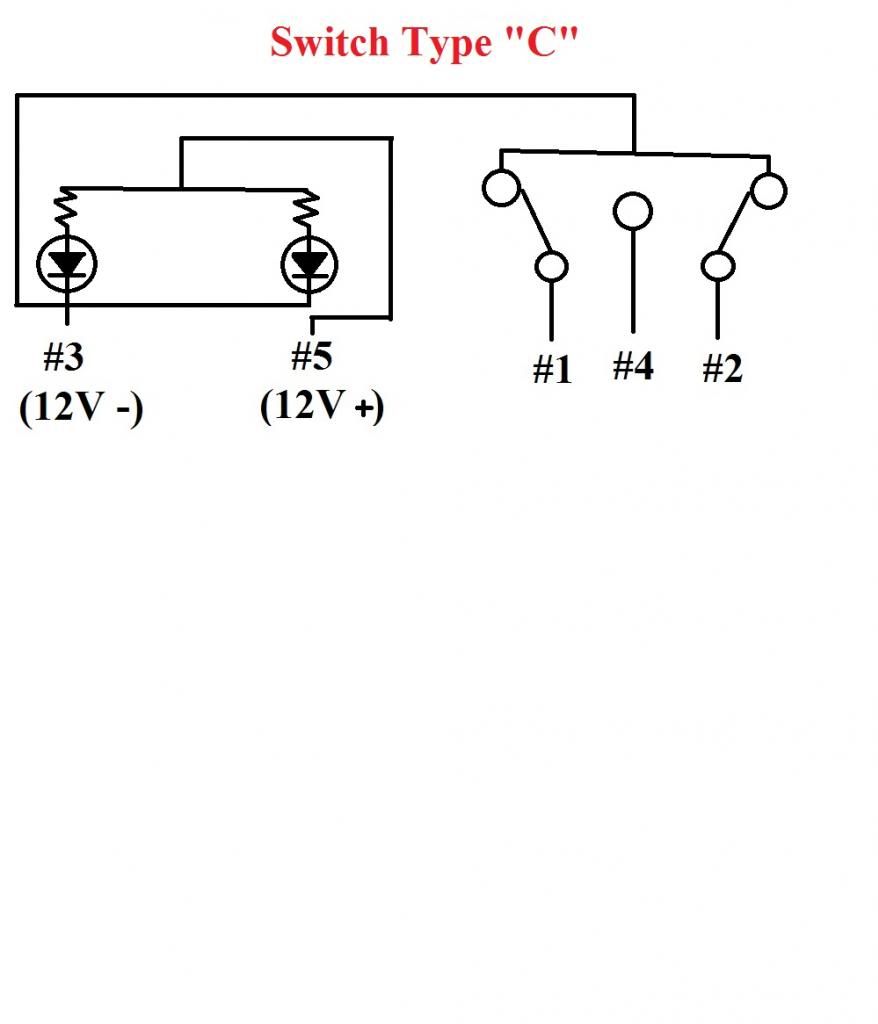
The window switches (Type C) are 2 dpst switches and both LEDs light up at the same time when powered.
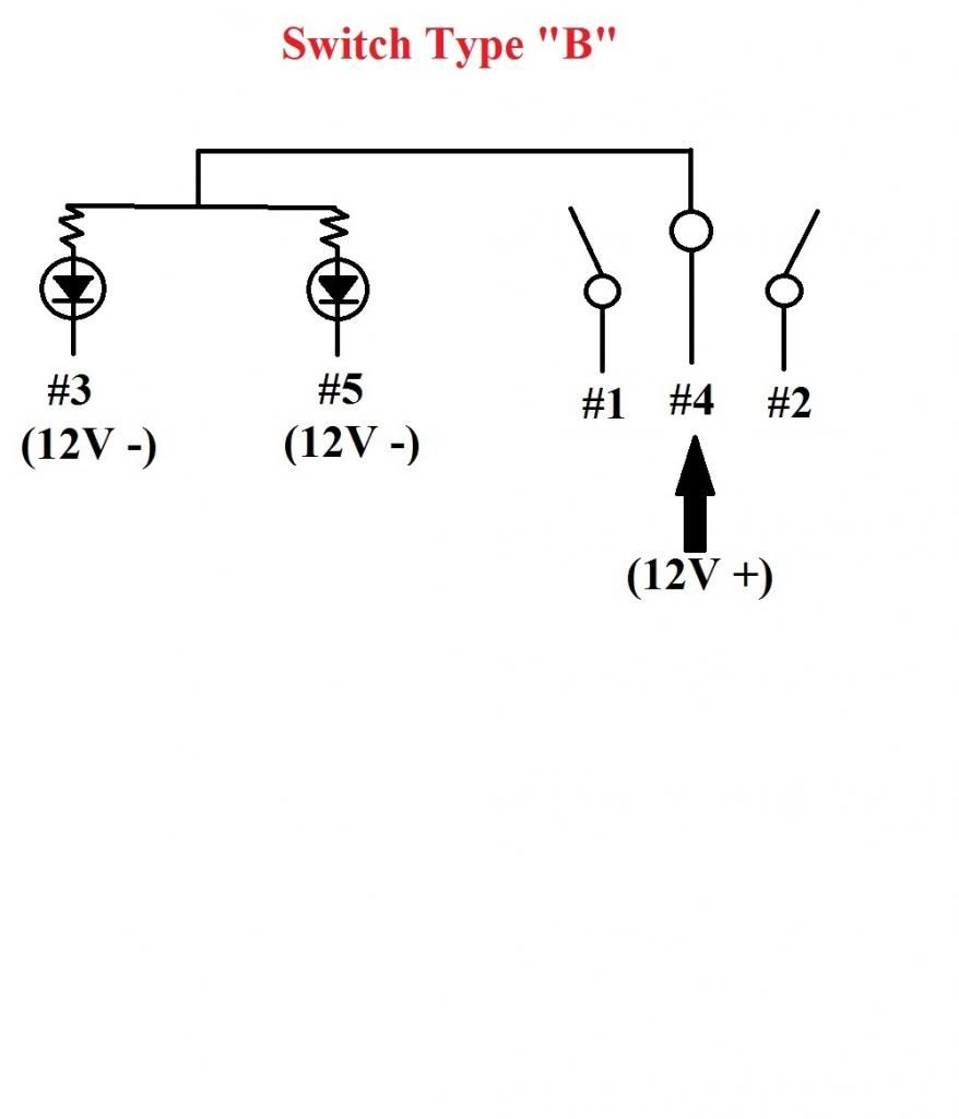
The defrost and security switches (Type B) are 2 spst switches and the LEDs light up independently to indicate that the function is active.
The top switch (Type A) is 2 spst switches and both LEDs light up together like Type C.
I can draw you a schematic in MS paint if you know how to read them...
The window switches (Type C) are 2 dpst switches and both LEDs light up at the same time when powered.
The defrost and security switches (Type B) are 2 spst switches and the LEDs light up independently to indicate that the function is active.
The top switch (Type A) is 2 spst switches and both LEDs light up together like Type C.
I can draw you a schematic in MS paint if you know how to read them...
05-15-2014, 05:42 PM
#5
Burning Brakes
Thread Starter
Thanks particle wave. A schematic would be great (ex-EE over here) if its not too much trouble. Seems like that schematic should be in the permanent links section!

Trending Topics
05-15-2014, 07:56 PM
#8
Burning Brakes
Thread Starter
Hmmm. Looks like I'm going to need a Type "A" switch.
How do I tell which switch is which type, A, B or C?
Also, on the Type A switch, it looks like both diodes always come on at the same time?
And BTW, the drawings are great!
How do I tell which switch is which type, A, B or C?
Also, on the Type A switch, it looks like both diodes always come on at the same time?
And BTW, the drawings are great!
05-15-2014, 09:51 PM
#9
The 986/996 cab top switch is the only type A that I'm aware of, but I've never seen certain switches in person, like PSM, footwell, etc. since I don't have those.
The switch type is labeled on the underside of each switch. You'll see the five pins and their corresponding numbers as well as switch type in tiny raised characters.
Switch types A & C light both diodes at the same time. Type B can light both diodes at the same time if both pins (3&5) are grounded. The diodes in B are a part of the switch circuit. Type A keeps both circuits separate.
I don't know about great...I probably could have done better with crayons and construction paper, ha!
Thanks, though.
05-15-2014, 11:27 PM
#10
Burning Brakes
Thread Starter
I just found this switch list... Doesn't give the type of each switch though.
This thread discusses the issue...
https://rennlist.com/forums/996-foru...id-move-3.html
996-613-141-00-A02 GLOSSY -1999 TRACTION CONTROL SYSTEM 222
996-613-145-00-A02 GLOSSY -2001 PSM OPTION 476
996-613-145-10-A05 MAT 2002- PSM
996-613-144-00-A02 GLOSSY -2001 CENTRAL LOCKING
996-613-134-00-A02 GLOSSY -2001 REAR WINDOW-DOOR MIRROR HEATING
996-613-134-10-A05 MAT 2002- REAR WINDOW-DOOR MIRROR HEATING
996-613-138-00-A02 GLOSSY -2001 CAB TOP SWITCH
996-613-138-10-A05 MAT 2002- CAB TOP SWITCH
996-613-136-00-A02 GLOSSY -2001 REAR WINDOW WIPER
996-613-136-10-A05 MAT 2002- REAR WINDOW WIPER
996-613-980-00 GLOSSY -2001 FOOTWELL LIGHTING
996-613-980-06-A05 *** MAT 2002- FOOTWELL LIGHTING
996-613-987-10-A05 MAT COUPE/TARGA SPORT EXHAUST
996-613-988-10-A05 MAT CAB SPORT EXHAUST
996-613-151-00-A02 GLOSSY -2001 POWER WINDOWS
996-613-151-10-A05 MAT 2002- POWER WINDOWS
996-613-147-00-A02 GLOSSY -2001 SUNROOF
996-613-147-10-A05 MAT 2002- SUNROOF
996-613-153-00-A02 GLOSSY -2001 SEAT HEATER LEFT
996-613-154-00-A02 GLOSSY -2001 SEAT HEATER RIGHT
996-613-153-10-A05 MAT 2002- SEAT HEATER LEFT
996-613-154-10-A05 MAT 2002- SEAT HEATER RIGHT
996-613-157-10-A05 *** MAT 2002- TARGA GLASS ROOF
996-613-119-10-A05 MAT 2002- SHADE FOR TARGA TOP
996-613-155-00-A02 GLOSSY 2001 996 TURBO REAR SPOILER
996-613-155-10-A05 *** MAT 2002- 996 TURBO REAR SPOILER
Last edited by sjg1138; 05-15-2014 at 11:43 PM.
05-16-2014, 03:01 PM
#12
Burning Brakes
Thread Starter
I'm determined to use one switch to control the OBC and to display the status of the Spoiler (no idea why I have this obsession). Unfortunately, the OBC hack requires the switch to bring two lines to ground and the Spoiler Deployed Status line is a ground output so the collector side of the LEDs would need to have + on them and would light up when the Status line goes low. Unless I'm missing something, this cant be done with any of the switch circuits as is.
One idea I have is to use two relays on the OBC switches to flip them from + to - so that they can be used to tell the OBC what to do. Sound like a good idea? I could use switch type B and the LEDs would light up when the Status indicator line goes low.
One idea I have is to use two relays on the OBC switches to flip them from + to - so that they can be used to tell the OBC what to do. Sound like a good idea? I could use switch type B and the LEDs would light up when the Status indicator line goes low.
05-16-2014, 03:10 PM
#13
Three Wheelin'
I'm determined to use one switch to control the OBC and to display the status of the Spoiler (no idea why I have this obsession). Unfortunately, the OBC hack requires the switch to bring two lines to ground and the Spoiler Deployed Status line is a ground output so the collector side of the LEDs would need to have + on them and would light up when the Status line goes low. Unless I'm missing something, this cant be done with any of the switch circuits as is.
One idea I have is to use two relays on the OBC switches to flip them from + to - so that they can be used to tell the OBC what to do. Sound like a good idea? I could use switch type B and the LEDs would light up when the Status indicator line goes low.
One idea I have is to use two relays on the OBC switches to flip them from + to - so that they can be used to tell the OBC what to do. Sound like a good idea? I could use switch type B and the LEDs would light up when the Status indicator line goes low.
There's a guy on ebay that sells a kit of some sort for this (including the indicator light), so it must be possible. Here's the thread where I did the OBC hack.
05-16-2014, 03:40 PM
#14
Burning Brakes
Thread Starter
Cool. Thanks.
You said in the post "The 4 functions are up, down, set, and reset. Up and down are redundant, since you can just continue up until you circle to your choice. Set is only needed for the speed gong, which I wont use . So, I can get away with one two-contact momentary switch."
Like you, I'm going to use one switch.
Do you happen to remember which pins in the gauge cluster connector are the Forward and Reset (assuming those are the ones you used).
What does the Reset line function do in the OBC?
and here is an UGLY circuit diagram. Just in case you need an example.
05-16-2014, 04:13 PM
#15
Rennlist Member
There's a guy on ebay that sells a kit of some sort for this (including the indicator light), so it must be possible. Here's the thread where I did the OBC hack.
I actually haven�t hooked it up yet, but I have read postings on another site from people who have and they say it works properly.