When you click on links to various merchants on this site and make a purchase, this can result in this site earning a commission. Affiliate programs and affiliations include, but are not limited to, the eBay Partner Network.
Some members here may remember Ahsai’s incredible thread where he tapped into the oil temp sensor pin in the DME and created a circuit to drive a VDO oil temp gauge. Here is that thread for reference: https://rennlist.com/forums/showthre...errerid=188196
I was very impressed with his work and decided I would give it a shot and build one for my car. I did take some liberties with his design and develop it a bit further. Since I would be using the VDO vision gauge, I simplified the circuit and eliminated the switch, LED, and trim pot, since they are not needed when using the VDO gauge.
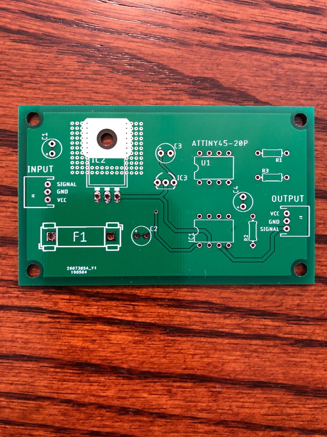
I tried to make the circuit on a breadboard and soon discovered my soldering skills were not up to the task. So I went ahead and created a gerber file and sent it off to get a pcb made. I also added connectors for the input and output, and incorporated the heat sink into the surface of the pcb. The result came back great and simplified the soldering enough so I was confident in the task.
Here is a pic of the bare board:
Then programed the ATTiny with Ahsai’s code and populated the pcb with the components.
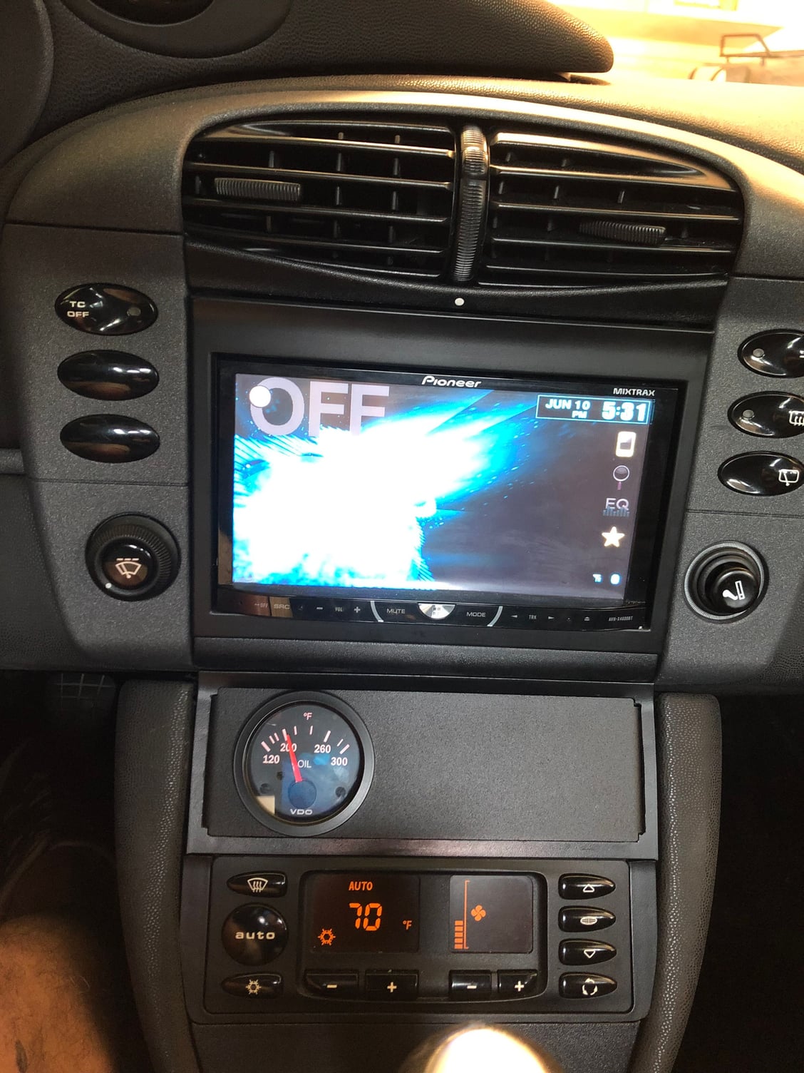
I decided to sacrifice my cubby and mount the gauge in a single DIN gauge pod I found on eBay.
PREMIUM Universal DIN Gauge Pod - 52mm (2-1/16") single pod radio mount https://rover.ebay.com/rover/0/0/0?m...2F262604293825
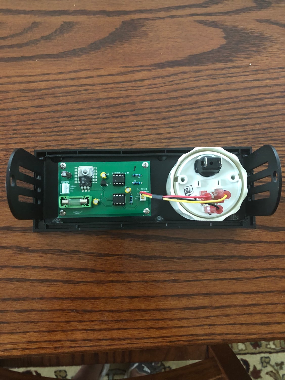
The mounting ring that came with the gauge is slightly taller than the DIN slot, so I had to sand it down, and I JB Welded standoffs to the back to mount the pcb.
Next I used a trim piece from the AC controls, modified to fit the mount from eBay,
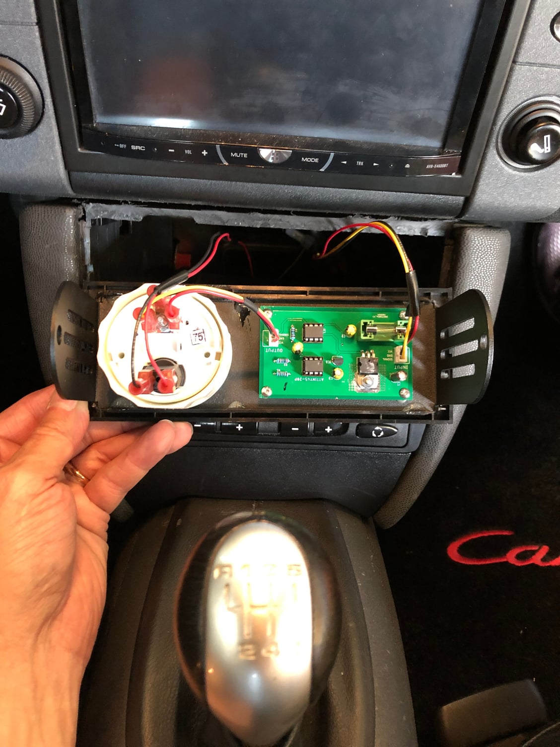
Here’s a pic of the finished assembly from the back.
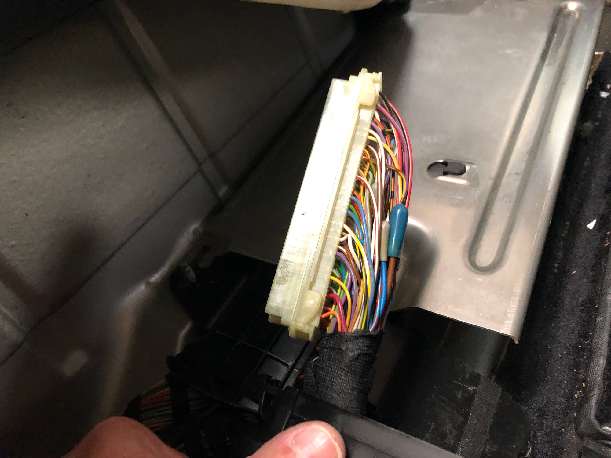
And wired up before installation. Power came from the unused phone connector that is tucked up into the center stack. The gauge light is wired into the circuit that runs to the ashtray light. The scariest part of this mod was tapping into the DME connector that contains the sensor wire. 88 wires come together here, I needed to find #73!, and I ran the wire up under the console to just above the AC controls.
That's very cool. It would be awesome if somehow we get rid of the speedo in the dash and just use the digital speedo (that's all I use anyways) and move the oil pressure gauge next to the oil temperature so you can actually read it!
@808Bill assuming you have all needed parts, I’d say it’s an easy weekend project. Actually assembling the circuit board is the easy part. I could do it in an hour.
Mounting the gauge and pcb to the DIN pod is also quick, but the JB Weld used to mount the standoffs needs several hours to harden, overnight for full cure.
I needed to make some minor modifications to the DIN slot above the AC controls and to the trim ring around the pod. This took a couple of hours, but I took my time so it looked as good as possible.
Wiring the assembly to the car took me 3 hours to access the DME, splice in the wires, and run them out of sight under carpeting, console, etc.
Could it be done quicker? Sure, but this is a hobby car for me, and I like to take my time and enjoy the process.
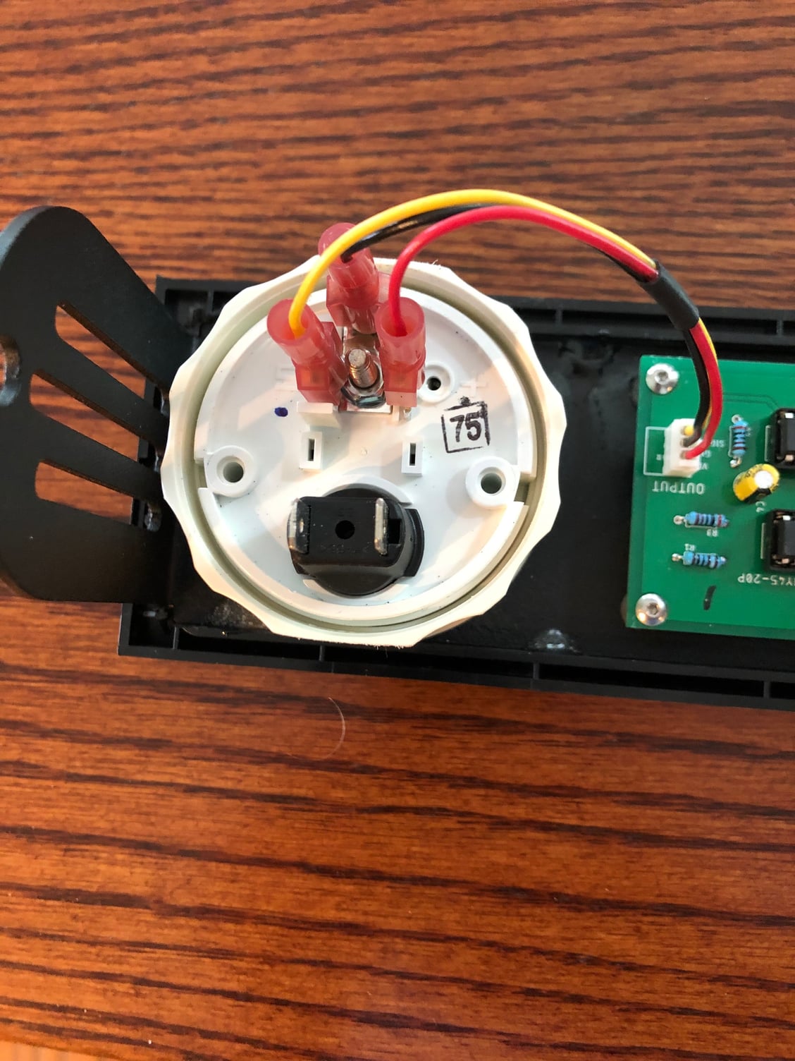
@turbogrill there are a total of 8 wires. 3 just go from the pcb to the gauge, Literally a few inches and is done on the workbench. 2 wires (12v power and ground) to the pcb came from the unused phone connection right below the AC controls. 2 additional wires connect to the gauge lighting, I spliced into the light in the ashtray behind the window switches in the console. Only 1wire goes from the DME to the pcb. The. DME is located under the parcel shelf behind the passenger side back seat. I ran it under the carpet in the rear and under the console and forward to where I mounted the gauge. All wiring is in the car interior, nothing in the engine compartment or frunk.
Very cool! I don't think it would take much to make a board small enough to attach it to the back of the gauge (or maybe even mount it vertically next to the gauge as-is to make room for an additional gauge or two.
@808Bill assuming you have all needed parts, I’d say it’s an easy weekend project. Actually assembling the circuit board is the easy part. I could do it in an hour.
Mounting the gauge and pcb to the DIN pod is also quick, but the JB Weld used to mount the standoffs needs several hours to harden, overnight for full cure.
I needed to make some minor modifications to the DIN slot above the AC controls and to the trim ring around the pod. This took a couple of hours, but I took my time so it looked as good as possible.
Wiring the assembly to the car took me 3 hours to access the DME, splice in the wires, and run them out of sight under carpeting, console, etc.
Could it be done quicker? Sure, but this is a hobby car for me, and I like to take my time and enjoy the process.
@turbogrill there are a total of 8 wires. 3 just go from the pcb to the gauge, Literally a few inches and is done on the workbench. 2 wires (12v power and ground) to the pcb came from the unused phone connection right below the AC controls. 2 additional wires connect to the gauge lighting, I spliced into the light in the ashtray behind the window switches in the console. Only 1wire goes from the DME to the pcb. The. DME is located under the parcel shelf behind the passenger side back seat. I ran it under the carpet in the rear and under the console and forward to where I mounted the gauge. All wiring is in the car interior, nothing in the engine compartment or frunk.
Nice!
When the 996 was a track car my plan was to do something similar but with a Circuit Express (https://www.adafruit.com/product/3000).
You don't have time to look at a gauge when racing, has to be lights.
But I don't track the car anymore so don't see the point.
 06-10-2019, 08:58 PM


 How long (knowing what you now know) would this take?
