When you click on links to various merchants on this site and make a purchase, this can result in this site earning a commission. Affiliate programs and affiliations include, but are not limited to, the eBay Partner Network.
Do you remember the thread size? Any particular supplier?
I wonder if capping off these lines actually leaves the pump pressurizing the circuit - sort of like when you have the steering rack all the way to a stop and the peak pressure in the pump rises. The other option would be to connect the two lines, which means the pump would just circulate the fluid, but it would not have any pressure - and if that is shared with the power steering, it would disable that assistance.
Does the pump sound normal or it sounds stressed?
Cheers,
Mike
Damnit Mike, the engineering in ya threw a big wrench into the simplicity of it. So now I'm wondering (as you did) if doing this will cause other problems.
Last edited by OverBoosted28; 12-09-2014 at 05:30 PM.
Do you remember the thread size? Any particular supplier?
I wonder if capping off these lines actually leaves the pump pressurizing the circuit - sort of like when you have the steering rack all the way to a stop and the peak pressure in the pump rises. The other option would be to connect the two lines, which means the pump would just circulate the fluid, but it would not have any pressure - and if that is shared with the power steering, it would disable that assistance.
Does the pump sound normal or it sounds stressed?
Cheers,
Mike
You Know Mike, you bring a very important point and question. I honestly am not too sure. These lines are coming from a distribution block. If we put them together its a great idea, it will recirculate as one of them seems to be coming straight from the Reservoir. that would be the line with #17, 18, 19 on it.. Here is the diagram from PET which shows all lines coming from the distribution block and the 2 I have capped off. The pump sounds perfectly normal and does not sound any different.
Line 13 & 15 are coming from the distribution block which I capped off but if we join them together with the other will flow right into the reservoir.
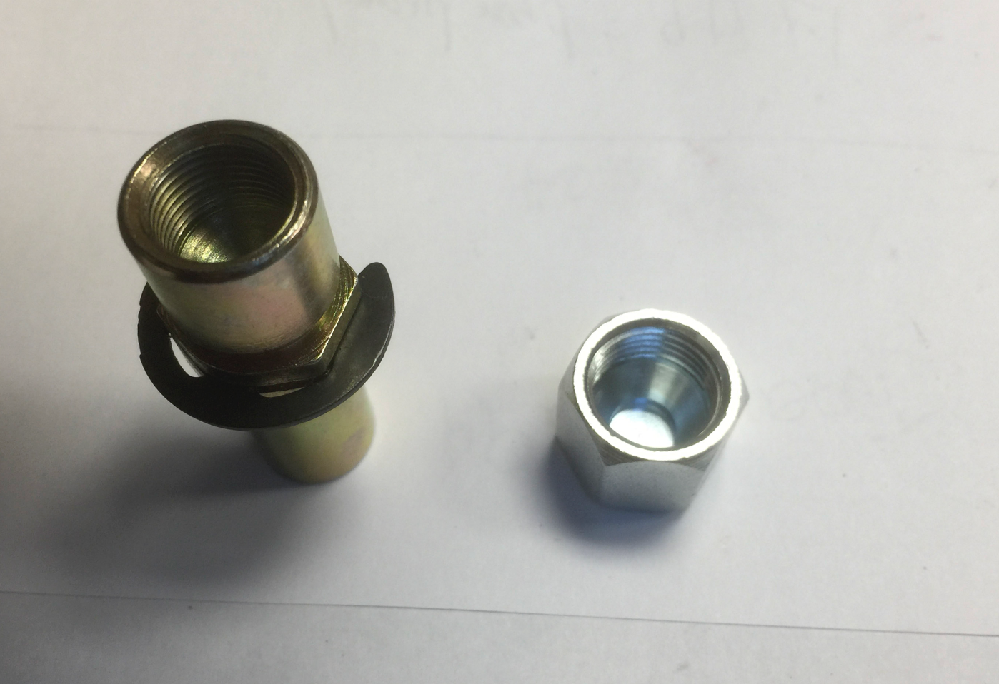
Thanks for the suggestion! Might try joining them. In terms of size I will take a picture of the AN size cap I bought.
The pump on the Turbo looks like it has two separate pumps/pressure circuits, one for power steering and the other for the clutch.
Interesting enough, the "distribution" block is called a "pressure switch" in PET, #23, which implies its more than just a flow through device. The pump output and output to the slave cylinder both go to #23 (see lines #15 - slave cylinder, line #16 - pressure side of the pump), along with a return to the storage tank #20. I bet this "switch" is a pressure regulator, which keeps the pressure up on line #15 and thus pressurized the pressure tank #28 to be used by clutch activations after the engine/pump is not running.
The implication of this is that if we plug line #15, this should be Ok since the pressure switch will just keep that line pressured, and divert excessive fluid/pressure back to the tank via line #20 since it acts as a pressure regulator.This lines up with peoples observations of no pump whine or noise when that line is plugged.
If the circuits are connected, it will do no harm, and allow fluid to move through the pump back to the reservoir - in fact putting in a tee with a valve would be a good way to flush the pentosin fluid in the tank. . It migh also reduce loading on the pump and thus increase available power to the wheels!
Of course, I am guessing this just from the diagram. What do you guys think?
Cheers,
Mike
I agree with the rationale, well explained. I might join them and call it a day.
I saw a pic of the internals of the turbo slave somewhere. There must be some resistance to the flow though it, even after the accumulator is pressurized? The high pressure side of the pump is really high... when I tried to repair a broken hose at the track using regular high pressure hose it would break in seconds while the car was just idling. I would worry a little that if the lines are just connected, high pressure fluid will shoot back to the reservoir. Maybe the distributor decreases the pressures, but the hose #16 has really high pressures.
I am just about ready to do my clutch (RS replacement) and do the clutch circuit while I am in there - but am having problems finding metric caps to cap the lines off up here in vancouver.
I think one line is M10 x 1.5mm and the other is M12 x 1.5mm? Does anyone have a specific source they used, or should I just scour the internet. I assume you removed the flex lines and capped it off on the hard line ends?
Mike have you tried Green Line on venables? If you need the line to take into a store to find the right size, I should have what I've taken off and you can borrow it.
I am just about ready to do my clutch (RS replacement) and do the clutch circuit while I am in there - but am having problems finding metric caps to cap the lines off up here in vancouver.
I think one line is M10 x 1.5mm and the other is M12 x 1.5mm? Does anyone have a specific source they used, or should I just scour the internet. I assume you removed the flex lines and capped it off on the hard line ends?
Cheers,
Mike
I went to half the world here on my side of town. I found one cap and couldn't find the other, Had to source to JB weld, I capped it off with a little of JB weld. If in the future I need to remove it I could remove the head and bolt up a new line. I capped of the smaller one with JB weld of course. Its the one that could be detached and re attached with the L line on it.
I went to a few hydraulic places and they did not have the fittings - primarily I think because this is a automotive metric fitting. I googled around for brake line parts of that size and there are more hits, so I need to dig into that area a bit more.
Ryojo, have not tried Green Line yet, but went to New Line and Phillips - struck out on both counts. I will keep digging ...
After replacing the OEM TT slave (with like) back in '09, with less than 10k miles on replacement now, it is failing again since that repair (I guess these "age" out). Fluid overflow, release almost to the floor...
So I am going the MPL route, have ordered their NA clutch slave and will attempt this mod. Will hold off on pedal spring until I see how it feels, since I am use to 993 RS (tribute) track car clutch effort.
Was wondering instead of capping the lines by the slave, to instead plug the block where high pressure line exits the block and just "dust cover the line ends. Is there a concern of low pressure backflow from tank? If so, plug at tank also as an option?
Any source/links/specs/part#s on the line caps that have been successful to cap the TT PS assist lines?
Are all the TT slave parts transferable to the MPL (to complete the NA MPL) or are some OEM NA parts needed to complete the MPL for the mod/swap out on an exiting TT w/ a OEM slave (that failed... again)?
yeah, good old thread. I haven't thought about this for a while and not sure I can help. I removed all my hydraulics so don't know what needs to be blocked off and not affect the power steering. And I did look at the tt slave parts and they look similar to the na slave parts that need to be reused but I didn't have them side by side so don't know..., hopefully someone will chime in or if you figure it out you can let us know!
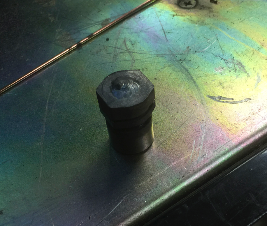
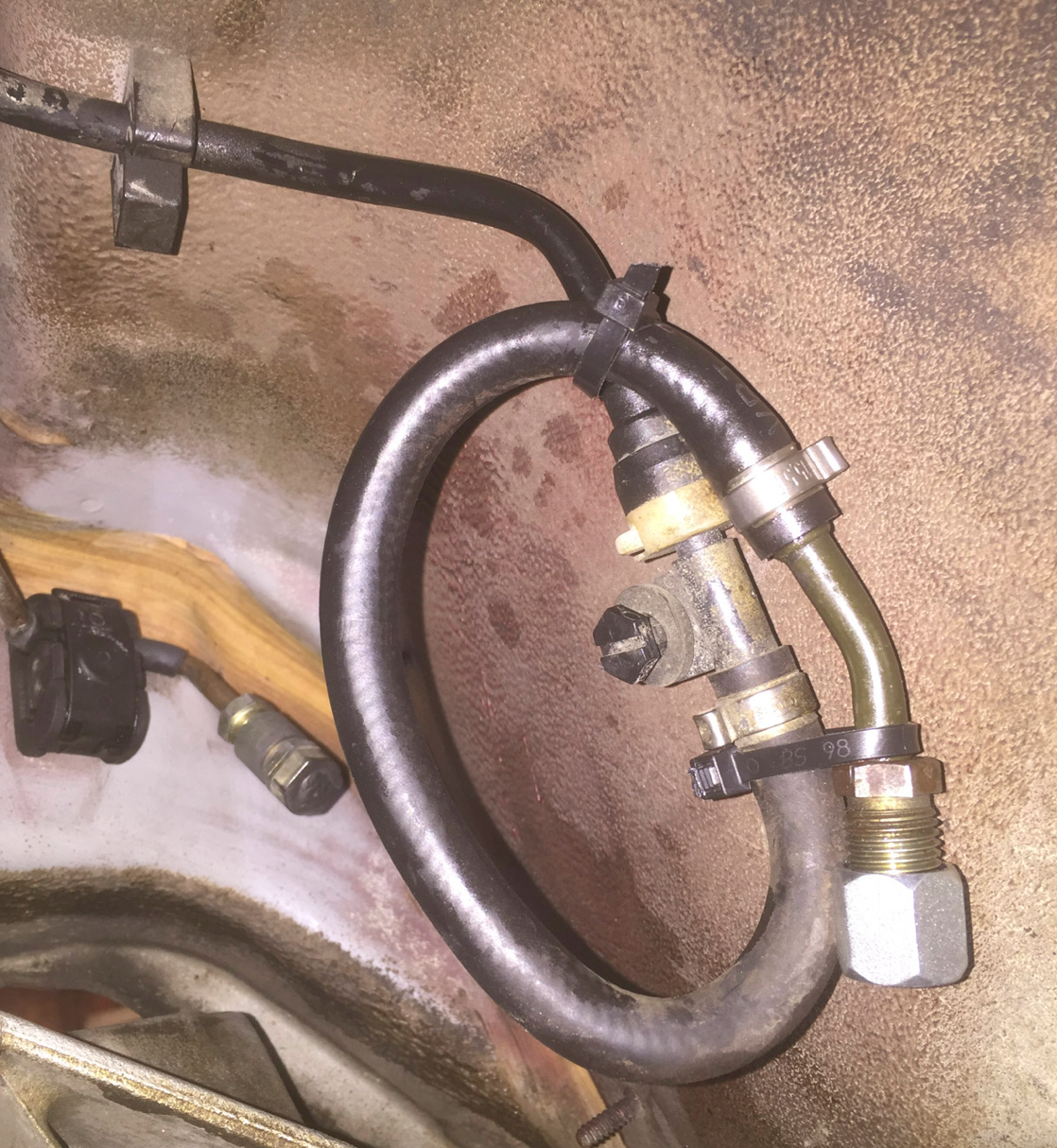
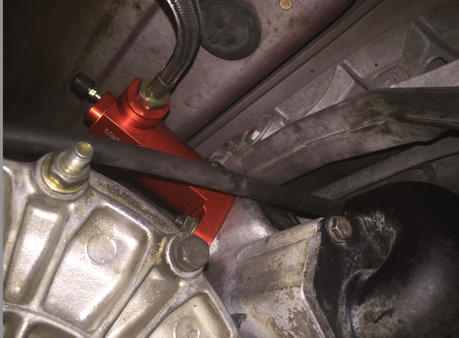
I capped the lines near the transmission because I wanted it easy to go back if I needed too. I could not find the exact cap that would work on the high pressure side, so I ended up finding a fitting for a hydraulic hose and TIG welded the open end closed.
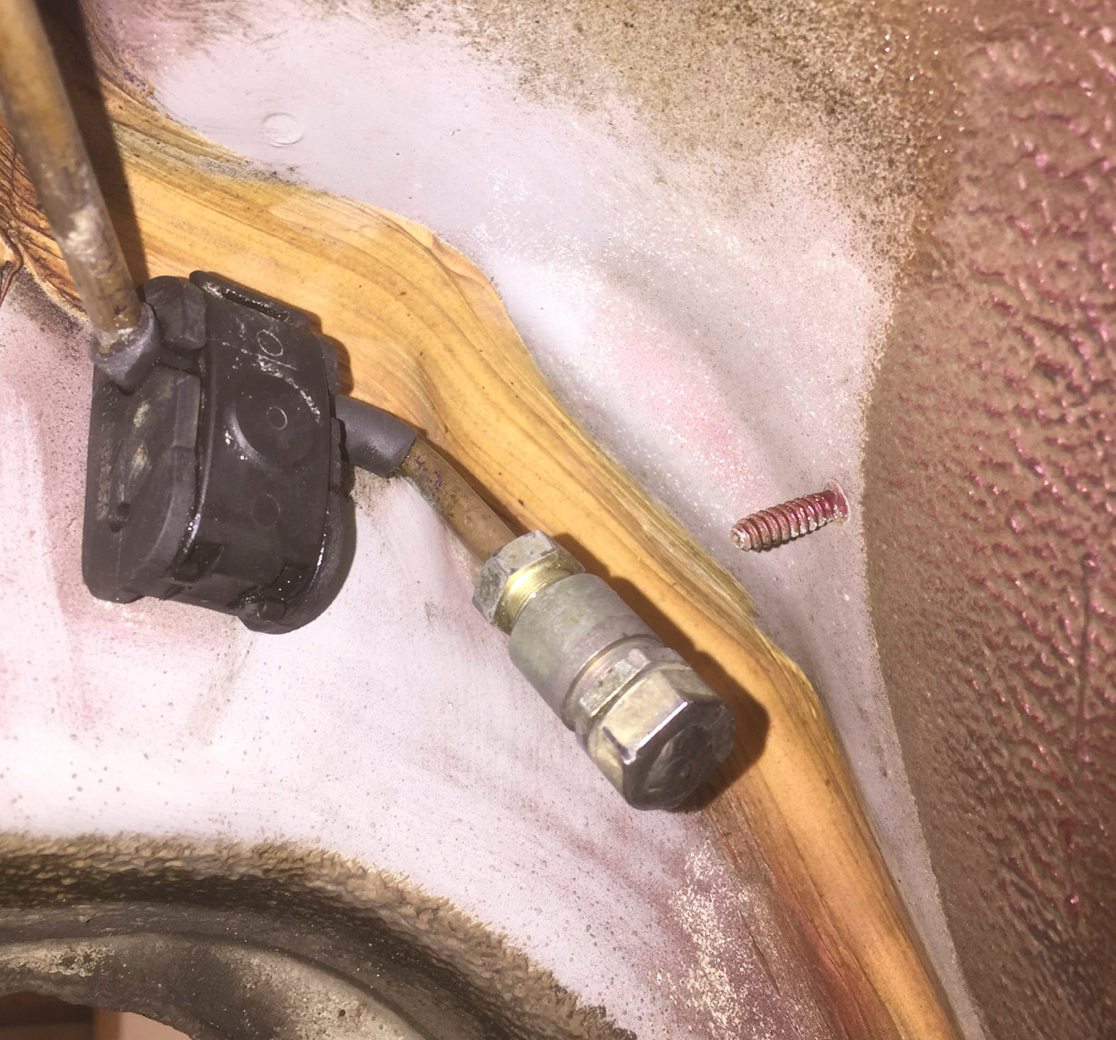
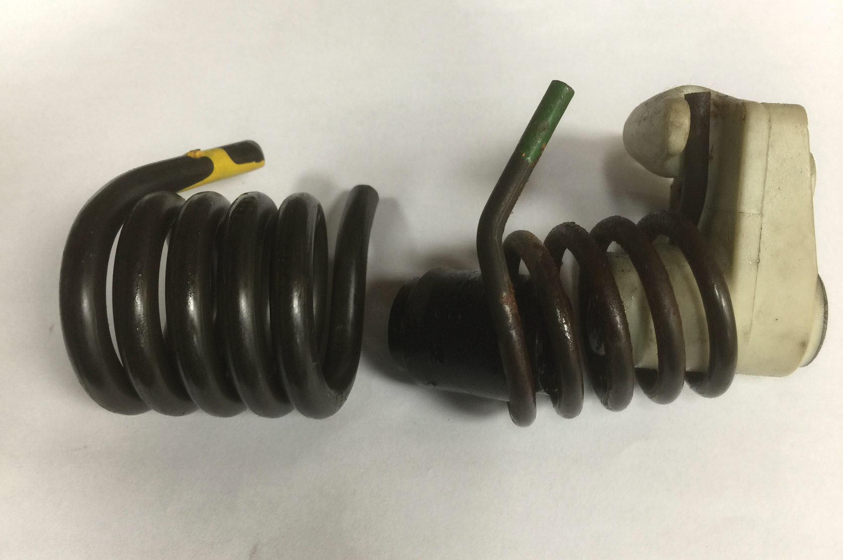
Below are some picts of what I did. I also included a spring picture to show what the difference is between the pedal cluster spring, and a shot with the MPL installed. I ended up not using the MPL, I have an very low engagement point on my clutch, and since the downside of the MPL is a shorter stroke, it did not push far enough to disengage the clutch. It might work now since i have some miles on the clutch, but I am used to the heavier feel now so no rush.
Cheers,
Mike
I capped the lines near the transmission because I wanted it easy to go back if I needed too. I could not find the exact cap that would work on the high pressure side, so I ended up finding a fitting for a hydraulic hose and TIG welded the open end closed.
Yah, that is right. I bought a clutch kit from Kevin, with a GT3 disk, RS flywheel and one of the higher clamping pressure plates. I installed it, and noticed the engagement point was very close to the floor - no problem driving it (once you adjust), but the MPL did not work right. I read later that there was a batch of pressure plates from Sach has perhaps were not correct and causes this issue. Anyways, the engagement point is still low, but higher so I might try it again.
However I have installed the MPL in another Turbo (Knight's) which he used for quite a while, but even with the MPL, his knee was complaining so we put back the power assist slave, He did note that the feel was not as good, but it was a lot easier on his leg!

 12-09-2014, 01:43 PM

 . It migh also reduce loading on the pump and thus increase available power to the wheels!