When you click on links to various merchants on this site and make a purchase, this can result in this site earning a commission. Affiliate programs and affiliations include, but are not limited to, the eBay Partner Network.
Have you considered trying to source a replacement of the original cable from Porsche? It's shown in the parts catalog as a seperate items so if they still available it would solve all you problems, as a small items it shoundn't break to the bank.
Porsche does have a replacement cable as I found out, but if I can repair what I have that is the best idea. I've got a micro C1 connector and pins coming, just would be nice to see a photo of an actual cable where the wires go into the C1 connector. Might just have to make a trip to my local dealer.
Perfect to show this wiring diagram -- so on the BROWN / GRND wire -- at the cable end (Yellow connector) it says this wire AND "outer ring" go into port #3. So what is the "Outer Ring"? All I can think of is it is the bare copper that is wrapped around the six other wires which are all covered by the white cable cover.
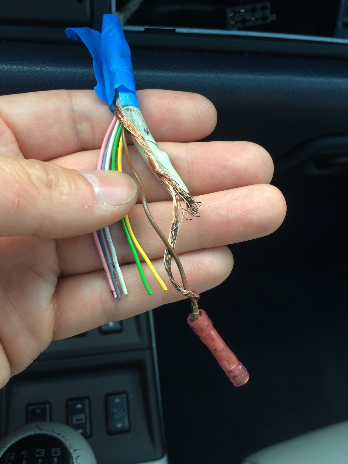
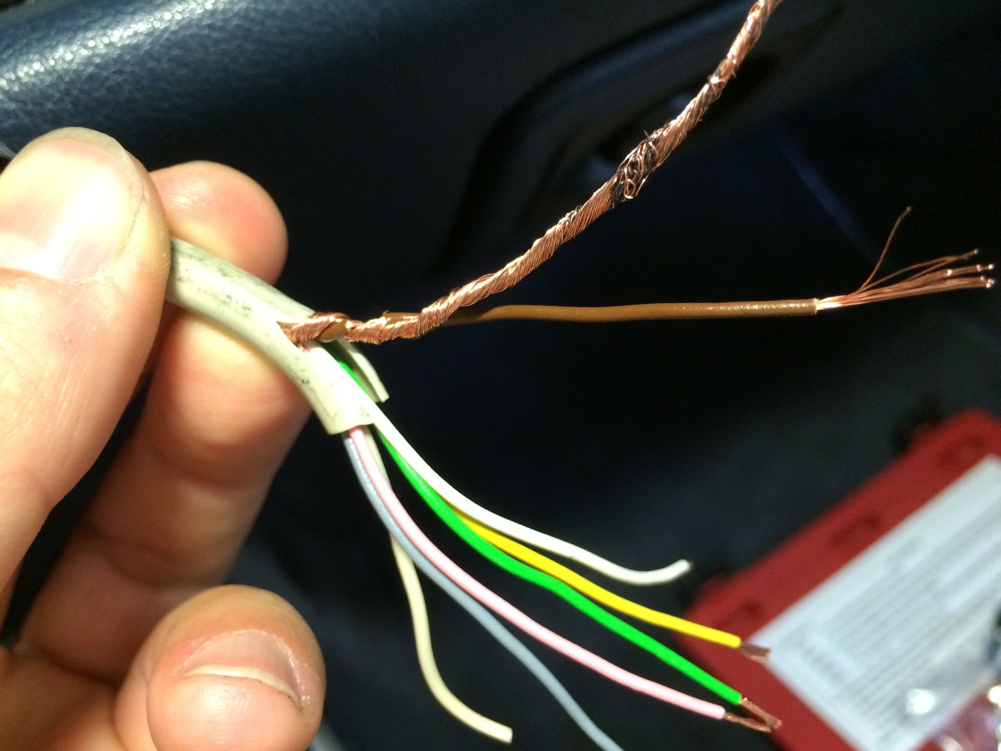
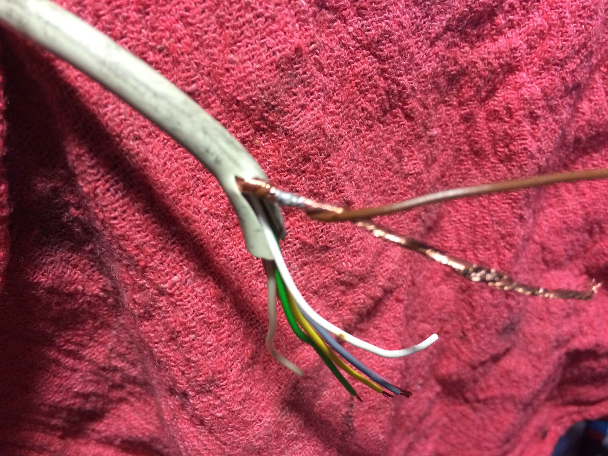
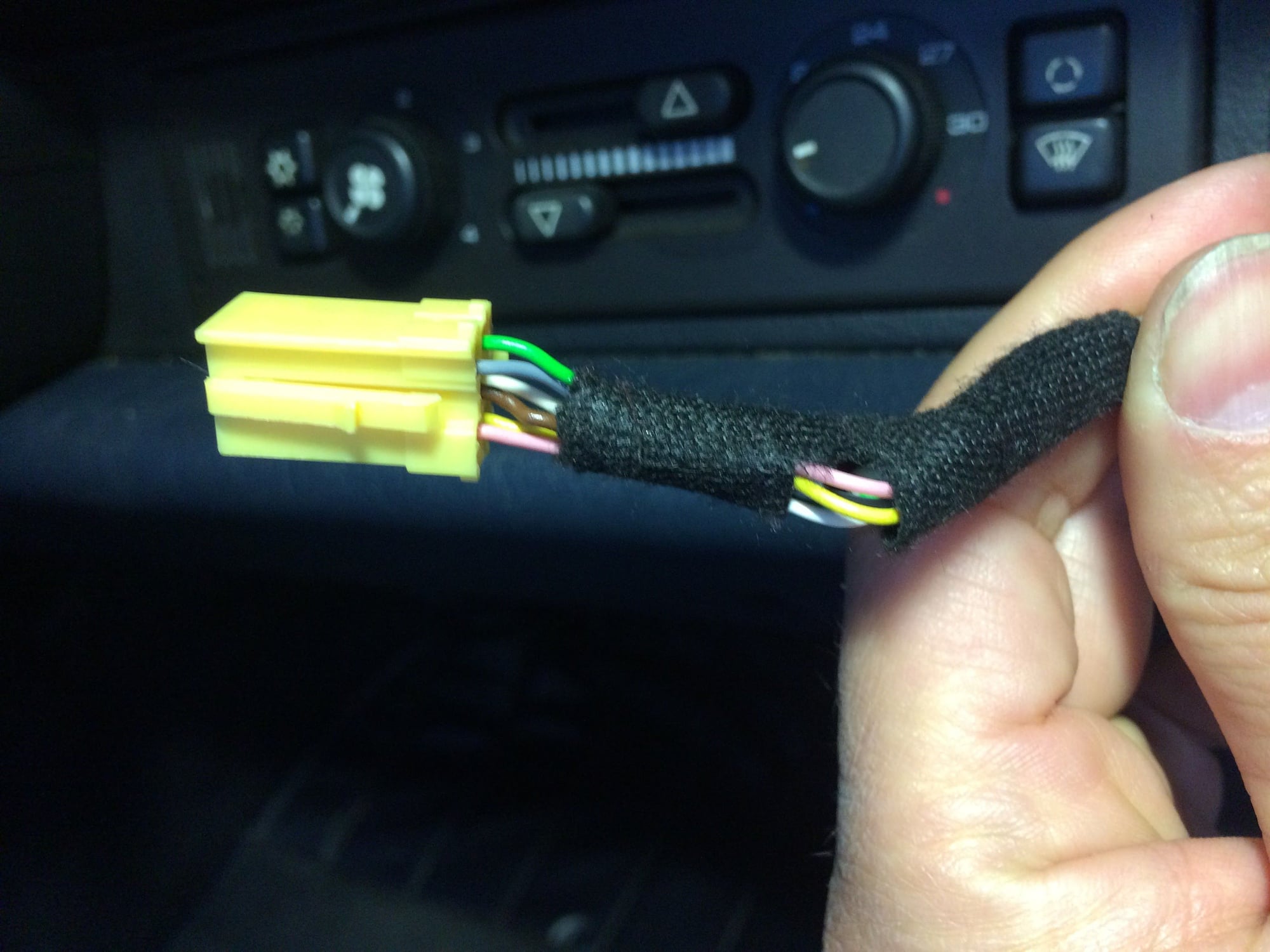
When I cleaned up the PO wiring, this bare copper that wraps around the six wires (the Outer Ring?) was spliced with the BROWN wire. So it seems that this Outer Ring must be spliced into the BROWN wire before it reaches the connector -- maybe in the Black covered section of the cable where the wires are coming out then go into the yellow connector. Here is a photo
Note the bare Copper wire that is spliced into the BROWN wire. This Copper wire wraps around all 6 other wires. Then the white cover surrounds everything. Is the Copper wire the Outer Ring that is called out in the wiring diagram above?
Well folks, the repair to the Nokia Amp cable is complete (well...). Parts came in for the Micro C connectors (eBay, the complete set with 18 pins and the C1, C2, and C3 sockets).
After doing the install it still did not work! I decided to not troubleshoot at this time as I will be replacing all the speakers in the next couple months. Since I may need to pull the Porsche Classic Radio (for another post perhaps -- highly recommended), to rearrange the cables in back so I can fully open the glove box, I might look into it further. It could be the Amp itself (when I got the car, the Kenwood radio that was there had power and all the functions worked -- just no sound) or the wiring is not right.
So lets assume the Amp is fine -- I would then look at:
1. OUTER RING and BROWN wires
a. should they be connected? In one spec sheet it calls for them to be connected, but that is the only instance. Anyone have an old cable they want to dissect?
2. WHITE wire
a. the standard is that it goes into pin #6 in the C1 socket. Yet there is a schematic that someone drew up that moves the white wire to pin #5 in the A socket. I wonder if you need to do this when you are not using the factory HU?
Pin #5 is already powering the antenna so maybe this is also necessary to trigger the Amp.
3. OFF-WHITE wire
a. this mystery wire (has a thin silver color wire inside) is not shown in any schematics that I have researched and was not connected to the previous stereo hack job that was done. I am thinking it was just to give the cable form, or does it have another purpose? I welcome input.
So, below is a look at the process of repairing the cable and some tips.
TIPS
1. Plan
a. make sure you plan how you want the final piece to look and gather all the parts and tools you will need to do it. Do some practice fits, etc. and plan the order for each step. Since I wanted to do a final heat shrink over everything, I first needed to cut the large heat shrink and put it on first, even though it would the last step in the process.
2. Tools
a. the rights tools are key. I think I have 10 different crimpers/splicers/cutters for wires -- each job is different. And based on this project, I decided I needed another crimper -- Engineer PA-09 Mirco Connector Crimper (Amazon).
b. I learned about this Tesa electrical tape from one of the forums -- it fabric and used by MB, VW, Audi, Porsche. Matches the existing wiring loom tape wrap. There are two versions 51608 and 50126 (high temp). Both are on Amazon. I would never go back to the old plastic tape.
3. Extra connectors
a. Trust me you will need more that what is required. Between testing, practice , and making real connections, you will go through a few. I like have 2x the number that you need on a project.
So here is the process in pictures :
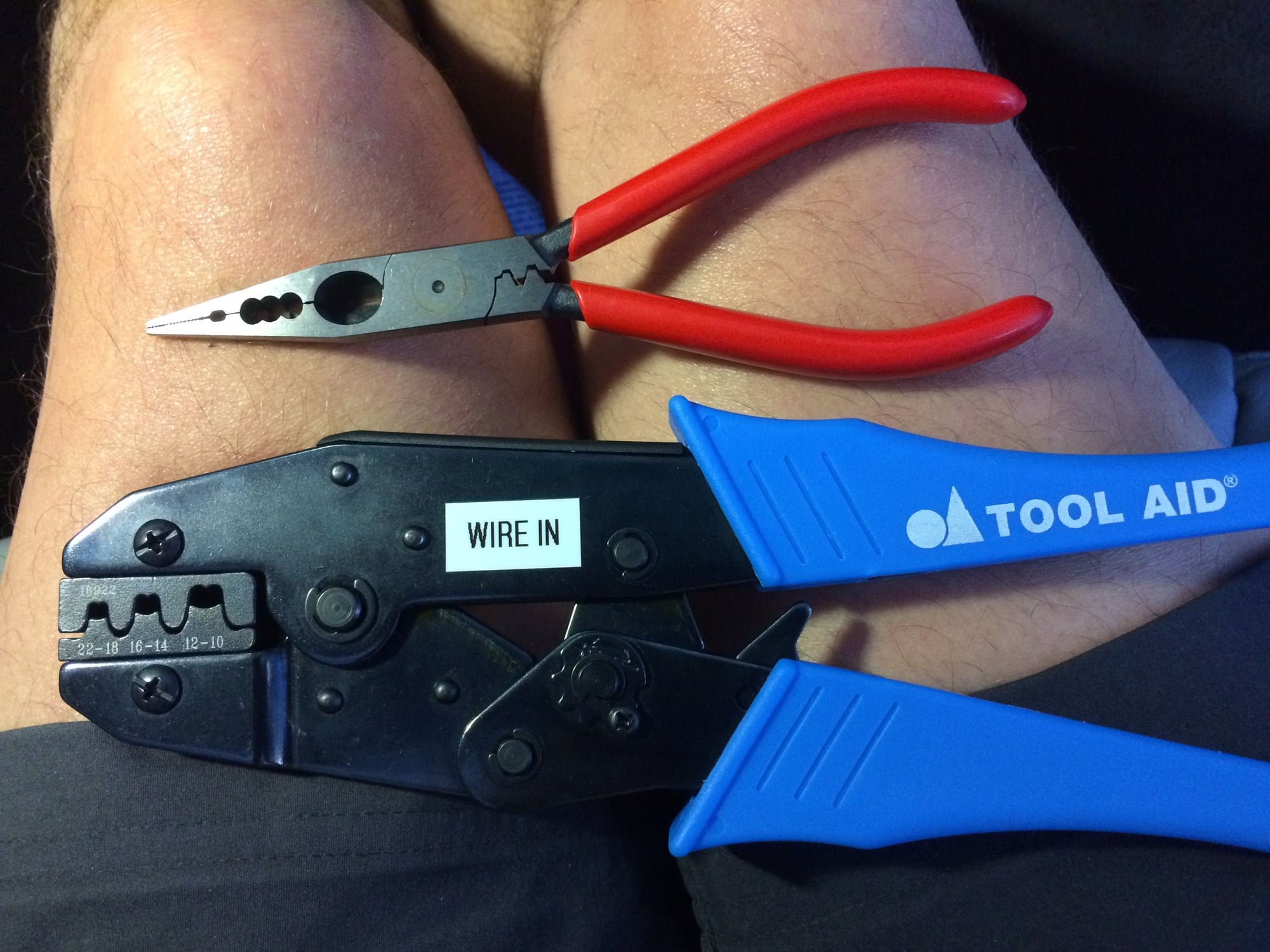
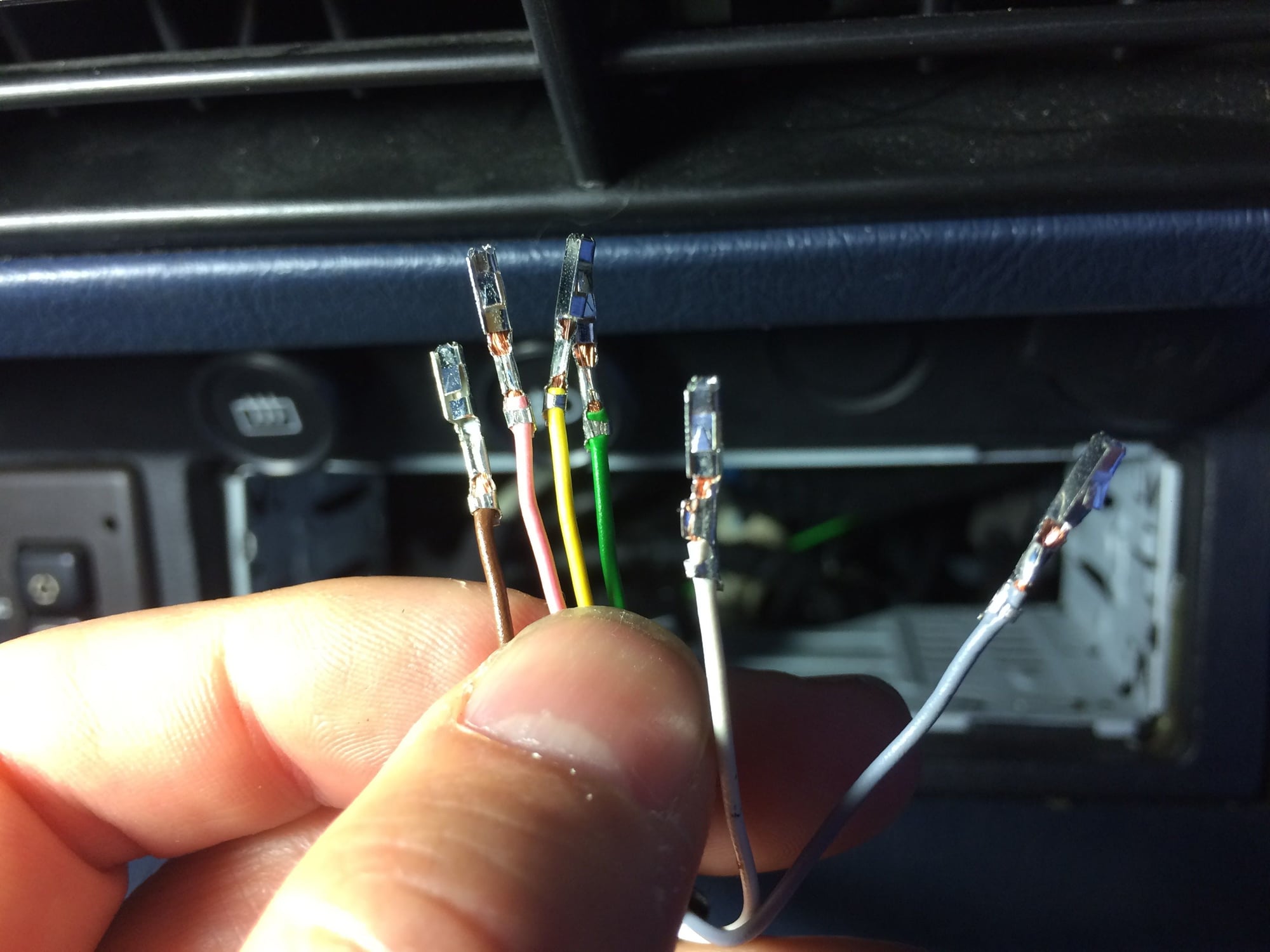
0. Couple of the tools. I found that if I used the red pliers to slightly crimp the connector on the wire, it made the final crimp using the Blue tool 100% easier. The Blue crimper is really too big for the job and I ordered the Engineer PA-09 -- this is the right tool to use.
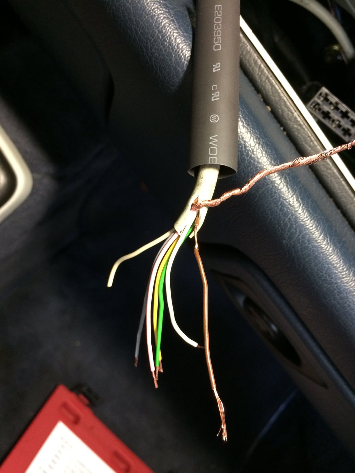
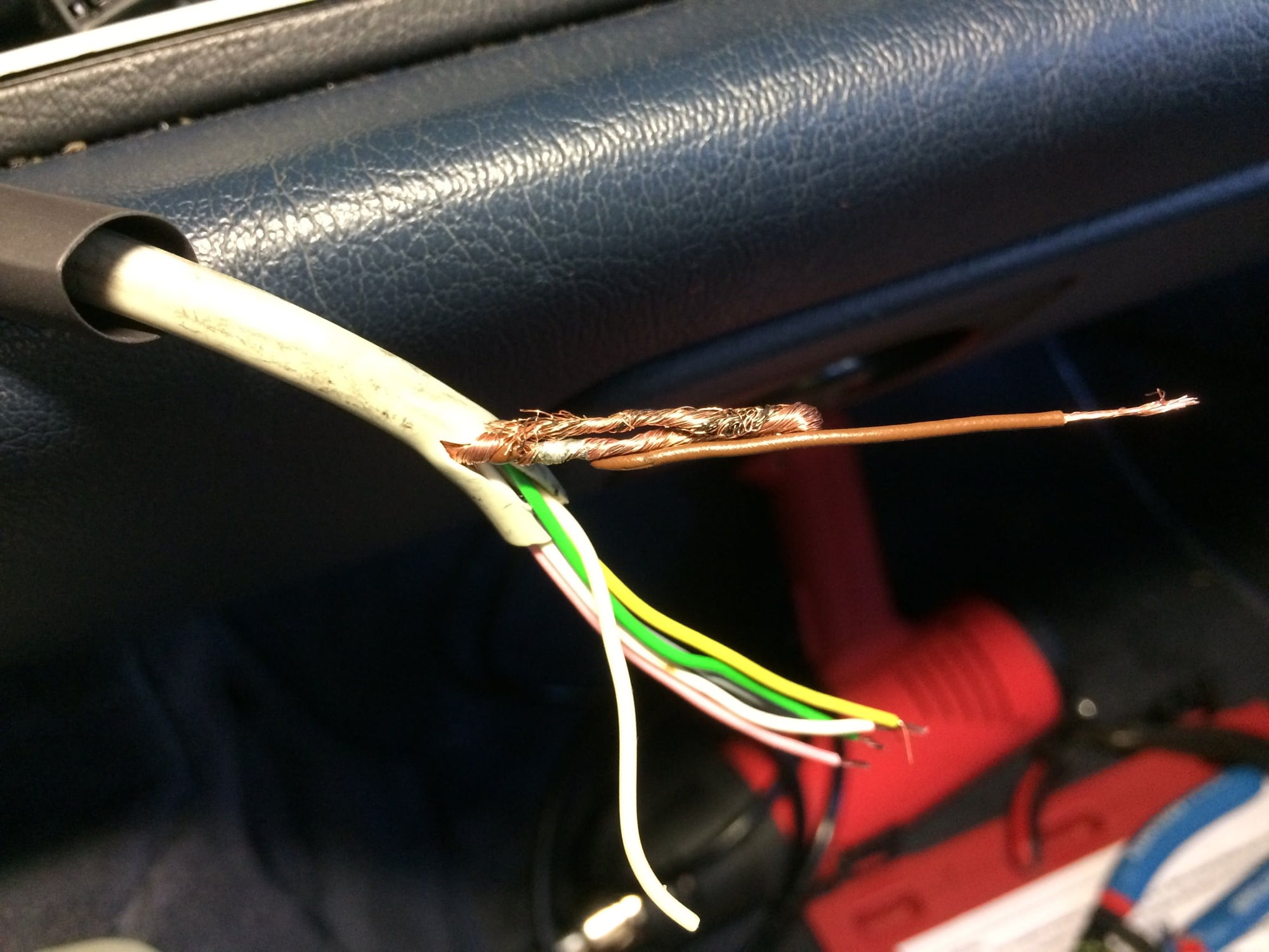
1. All wires now cleaned and trimmed to size, ready for stripping. Note the stray OFF WHITE wire to the left (#7 wire). Was not connected before so I am leaving that alone. Also note that I have already put the large heat shrink tube in place. You can see that I have stripped the BROWN wire near the white outer cover about 3/8 inch. This is to splice the OUTER RING and BROWN together here so that I only have wire to connect at the C1 socket
2. Here are the OUTER RING and BROWN wires twisted together.
3. To be safe, I solder the two wires as well.
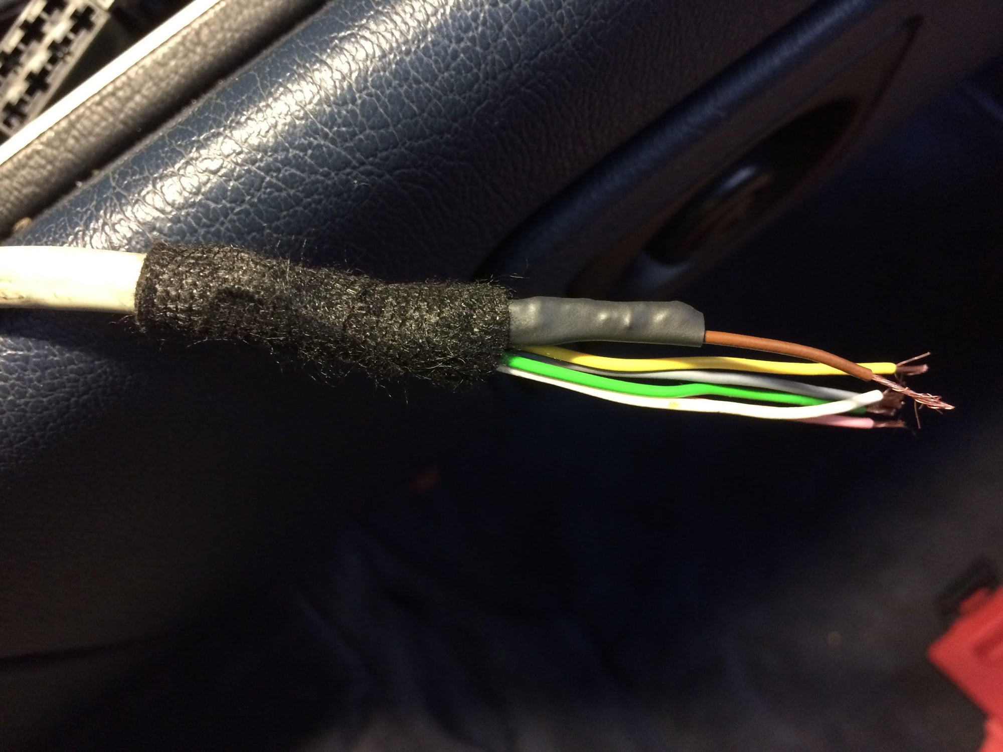
4. Then I folded the extra length of the OUTER RING wire (just in case I need it later)
5. And then heat shrunk the two wires so that they would not interfere with any other wires
6. Added some Tesa tape to secure.
7. All connectors done! What a PITA! The smaller crimper would have helped, but by doing the pre-crimp made all the difference. I tested the strength of the connection by hand -- all good. Thought about adding solder, but passed.
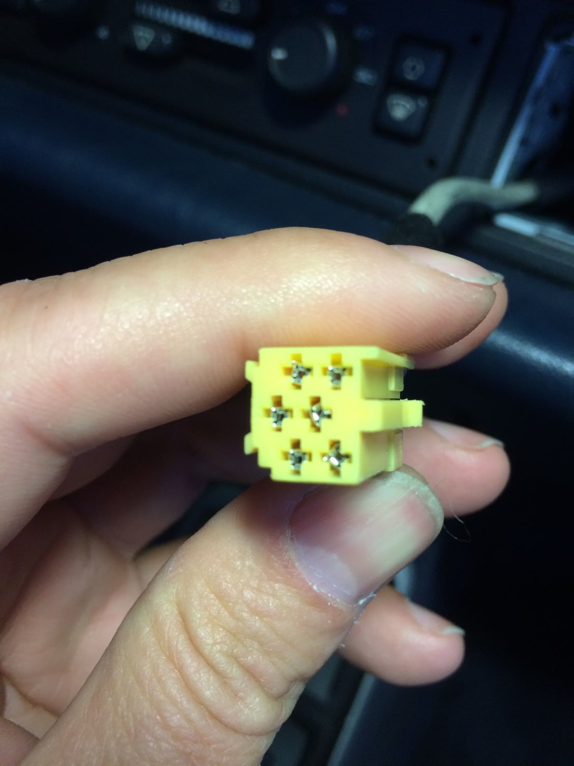
8. all connectors inserted into the socket. The pins lock into the socket. If they slide out after you put them in, rotate the pin 90 degrees left or right and try again. They go in a certain way to lock properly.
9. Back view to show the pins in the correct location. Added some Tesa tape to keep the wires from moving too much. After this I then pulled the heat shrink tube I first installed around all the exposed tesa tape and wires, heat shrunk it and finished the job -- looks factory (even better if you ask me!)
 06-18-2016, 04:08 AM