When you click on links to various merchants on this site and make a purchase, this can result in this site earning a commission. Affiliate programs and affiliations include, but are not limited to, the eBay Partner Network.
Over the past year I’ve done several DIY projects on my 993 and I wanted now to
document some of those for anyone wanting to do these projects as well.
The format I’ve decided to use is to put introductory material in the body of the
thread post and a link to pictures which are hosted on Google and to attach a PDF
file for the step-by-step instructions.
Many of these write-ups will contain a number of subtasks which could each be
a DIY for someone new to the 993, such as, how to remove and install the rear
heater blower assembly. To avoid constant duplication of the details for those
subtasks I will just give a one-liner for that step and focus the DIY on the core
task, such as in this first one on changing spark plug wires.
I’ve decided to not list all the tools required and just call out any special tools or
notes when necessary. Also, some steps might be viewed as optional but are
included if it makes the job easier. Depending upon whether you are doing
additional work to the core task being described can help you to decide if you
want to take an additional step, generally to remove some part or assembly.
The DIY contained below is for changing the spark plug wires, and by the way since my
car is a 97, the steps are specific to that model. This is another consideration you will
have when deciding what steps to leave out or others to add in.
For parts and materials you will want to get the ignition wire set from Beru. I
bought mine from Steve at Rennsport Systems. You’ll also want some dielectric
grease. Also get some copper anti-seize paste for lubricating fasteners. I did not
replace the distributor caps or rotors since they only had 40k miles on them and
they should go 60k. Just a little cleaning with an emory board shined them up
fine. I put 15k miles a year on my car so it won’t be long until I change them out
and since I’ve eliminated the rear heater blower assembly in favor of the RS
heater bypass option, getting at the distributors is easy. More on the RS heater
bypass in another DIY.
Attached are the DIY instructions and here is the link to the photo album:
I'm going to provide some updates to this thread related to the ignition
system. It will have to done in several posts to cover all I want to go over.
So in the DIY here I did not change the caps/rotors because I was under
the impression that they should go 60k miles which turns out to not be the
case, at least if you want optimum performance. In hindsight I should
have changed them at the same time as I did the wires.
I thought that the engine could be a little smoother on acceleration.
I felt I had left something on the table by not do the caps/rotors.
So I put in new caps/rotors at 106k miles. The old ones went into service
at 59k so I had gotten 46k miles out of them. The change was definitely
worthwhile as an immediate smoothness in acceleration and idle was felt.
Before I changed them I measured the resistance of the caps/rotors per
a Porsche document I found on this forum. User george996 posted up
this document which is a portion out of larger document in this thread: https://rennlist.com/forums/993-foru...n-problem.html
I'll attach it also as it's fairly small and I want to refer to it.
My old caps measured 968 - 1026 Ohms and the new ones
measured 965 - 1014 Ohms. Both were in spec which is 800 - 1200 Ohms.
The old rotors measured 1101 and 1110 Ohms.
The new ones measured 1125 and 1139 Ohms.
So the old ones did not fail the resistance test yet the new ones perform
much better. I attribute this to the air gap between the rotor and cap
which cannot be measured. It probably had increased and raised the
resistance in the secondary pathway enough to affect the performance
by increasing the spark firing voltage. This voltage is the amount
necessary to jump the air gap in the distributor and at the spark plug.
It is already quite high due to the lean air/fuel mixture and the
11.3:1 compression ratio, especially at idle. It is not unusual to see 60KV
and higher spark firing voltages.
I think the high spark firing voltages also contribute to the early wearing of
caps/rotors which were designed in the days of much lower spark firing
voltages (maybe 15 KV).
Bottom line is that now I think that to keep the engine running at peak
performance I will change the caps/rotors at a 30k miles service period.
Beru's Little Secret
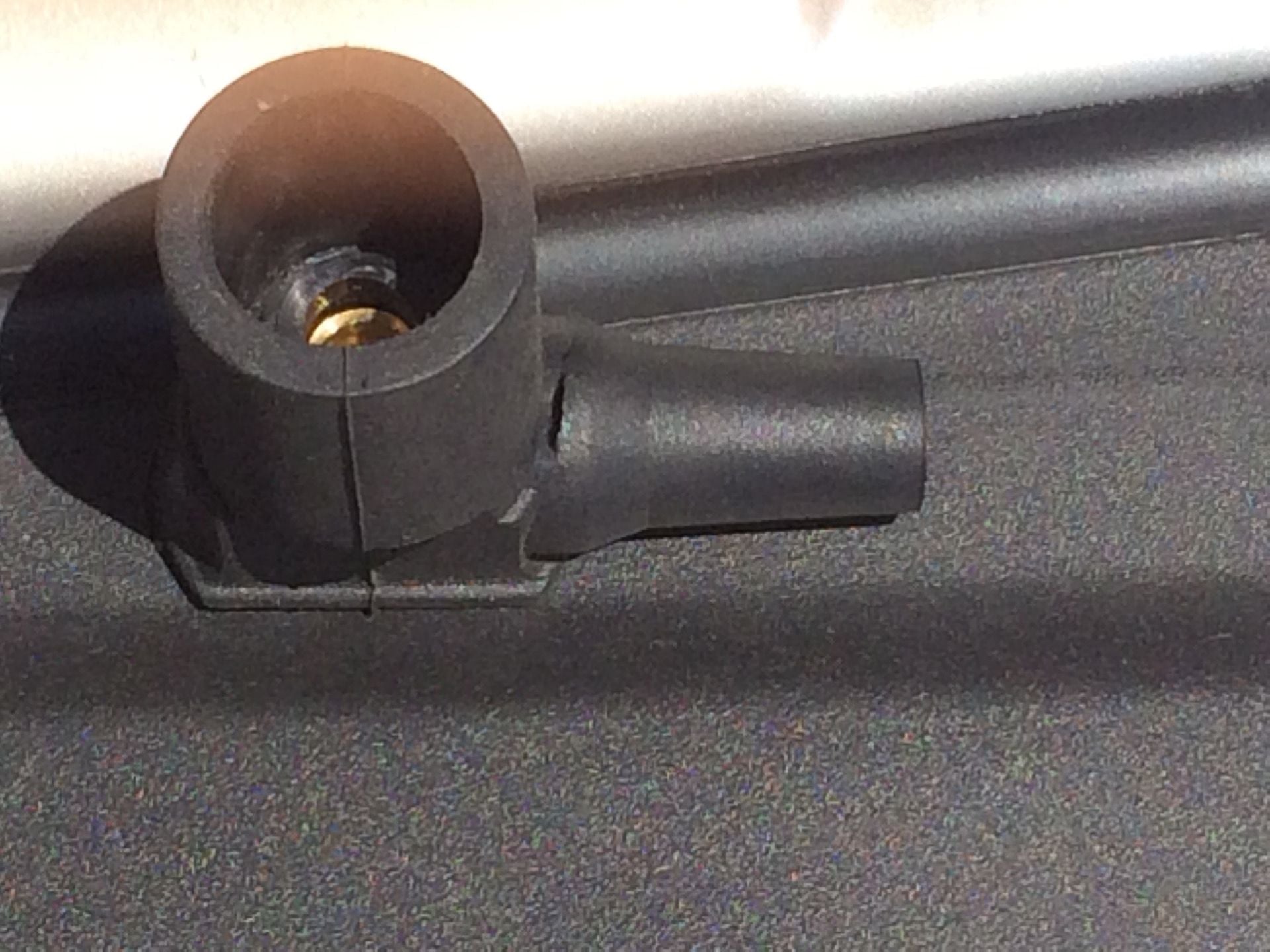
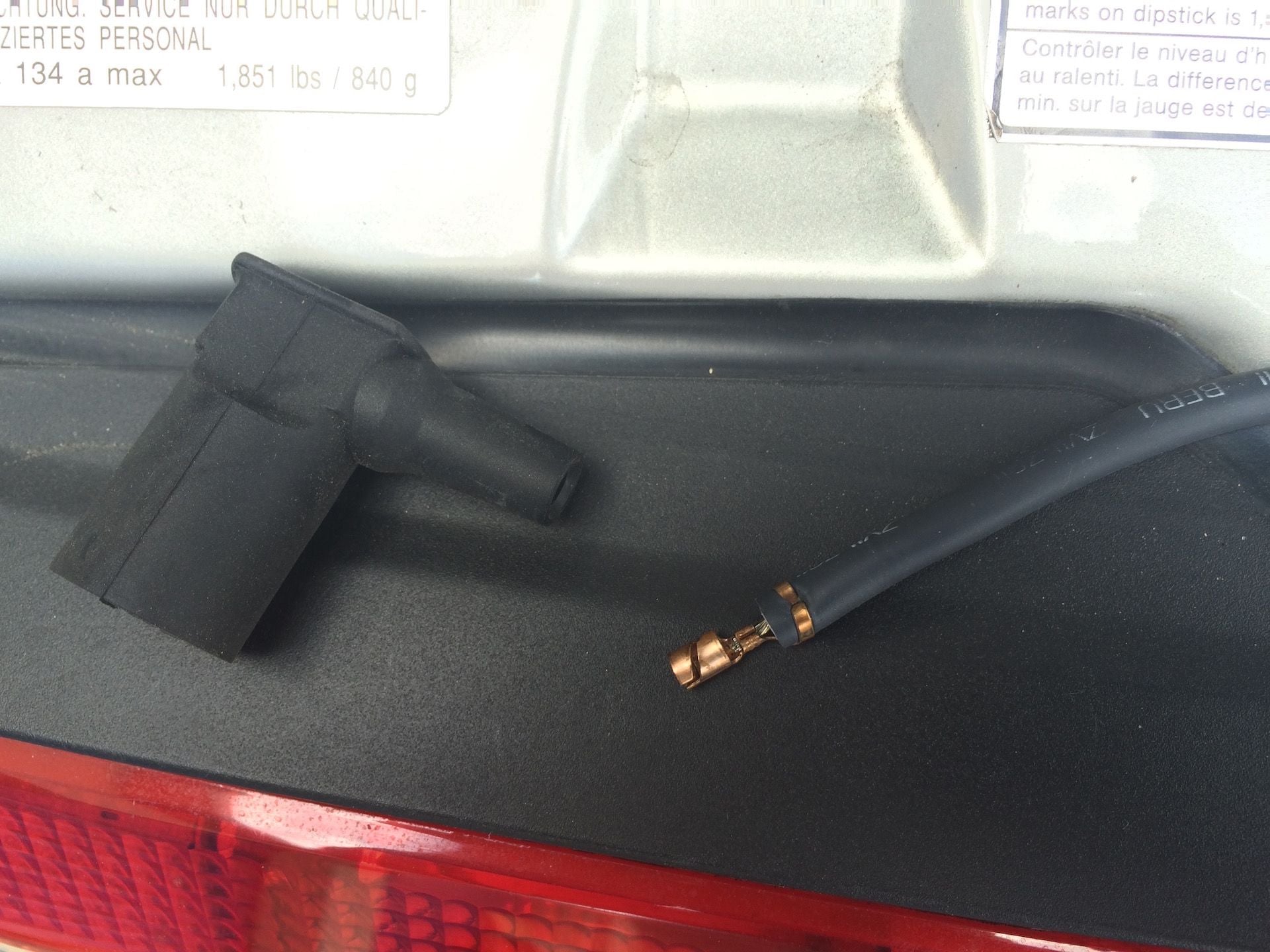
Now, an interesting thing happened while changing the caps/rotors.
I tore the rubber boot for II-6 spark plug wire at the distributor.
Here is a picture showing the tear.
Here you can see the shiny metal inside the rubber boot.
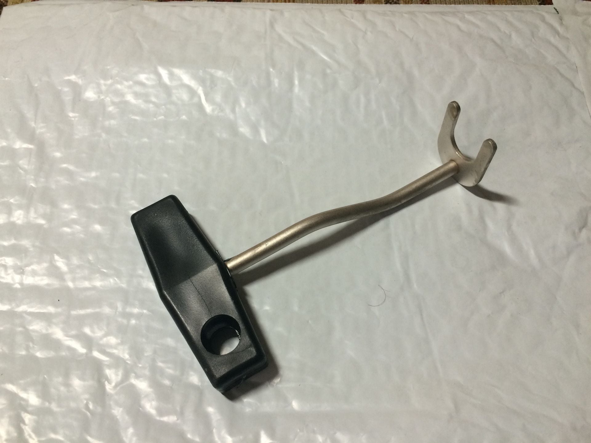
This tear was caused by me using the wrong tool to remove the connector.
The pliers in the picture are designed for another use and don't work well
for this application. With the pliers you are squeezing the boot while trying
to pull it off and fighting against yourself. When it slips it can tear the
soft rubber like I did. I have found a better way to remove the connectors
and more on that in just a moment.
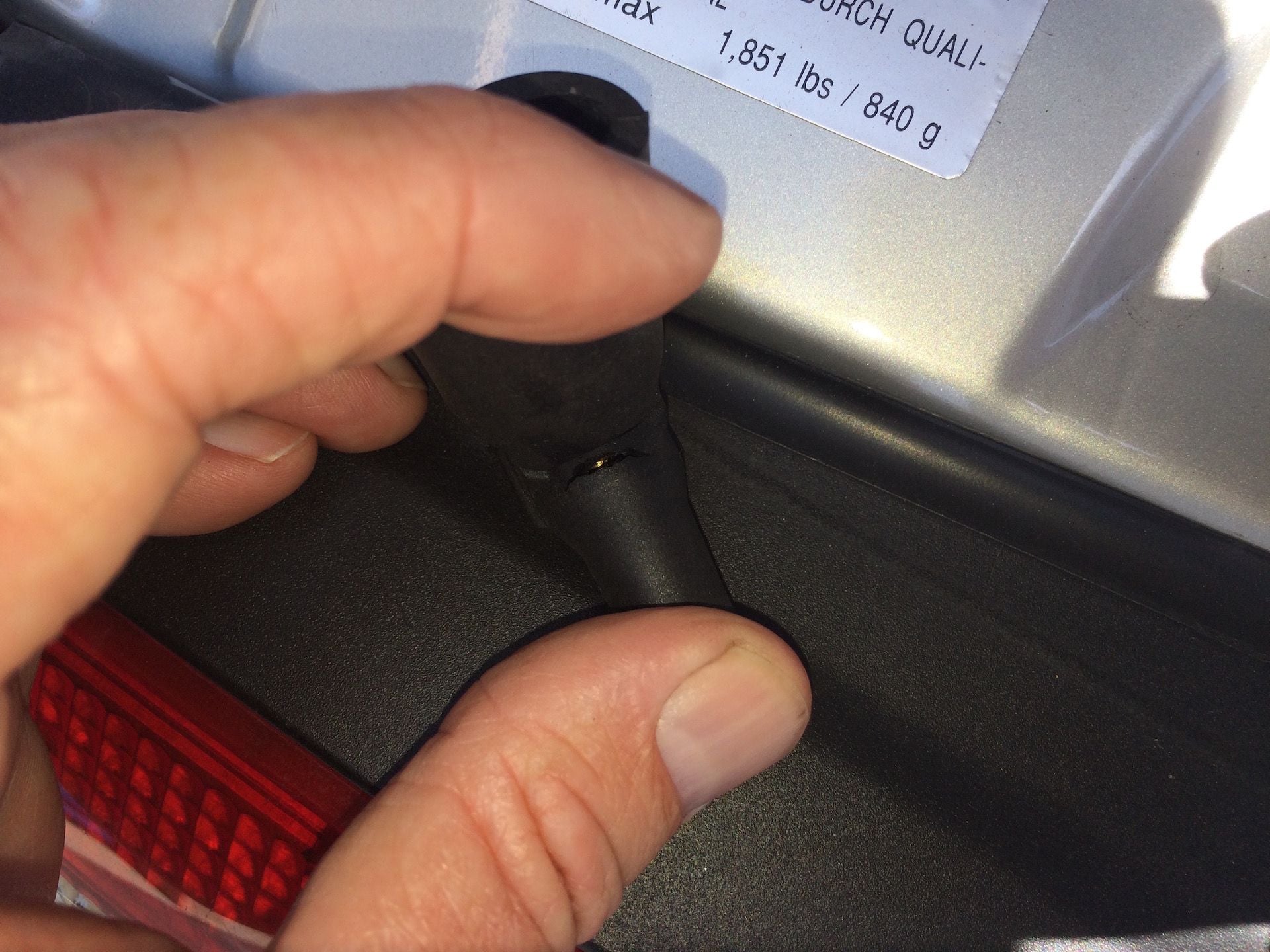
Knowing the high voltage running through these wires I thought it best
to replace this connector to avoid shorting to ground.
And here is where I ran into something that put a wrench into a simple
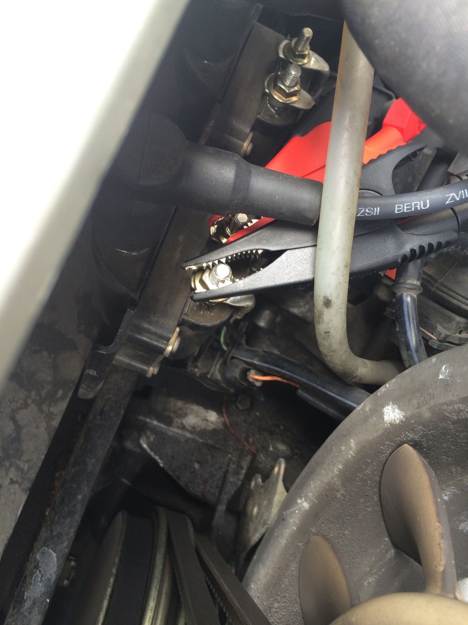
job. Take a close look at the wire connector in this picture.
Instead of an M3 threaded connector as per the original Porsche ignition
wire set, the aftermarket Beru ignition wire set uses a saw-tooth connector.
It's also used in the coil wire shown here.
This was a disappointment to me to find this out because I don't
remember ever seeing this discussed. I was under the impression that
it was constructed identical to the Porsche product and it is not.
Maybe this is why at $500 it is 1/3 the price of the Porsche wire set? And with
the Porsche wire set it's not even a set as only the individual wires are sold
(listing at $125 each).
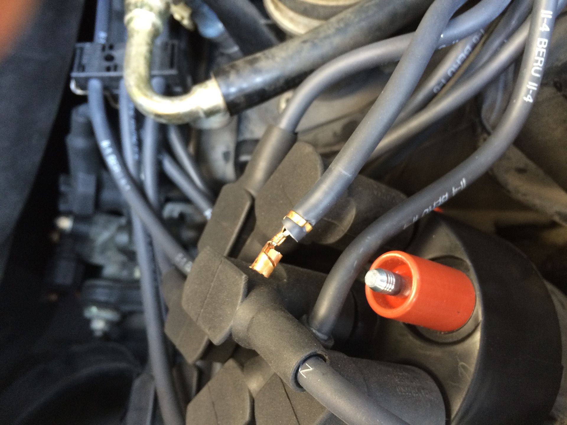
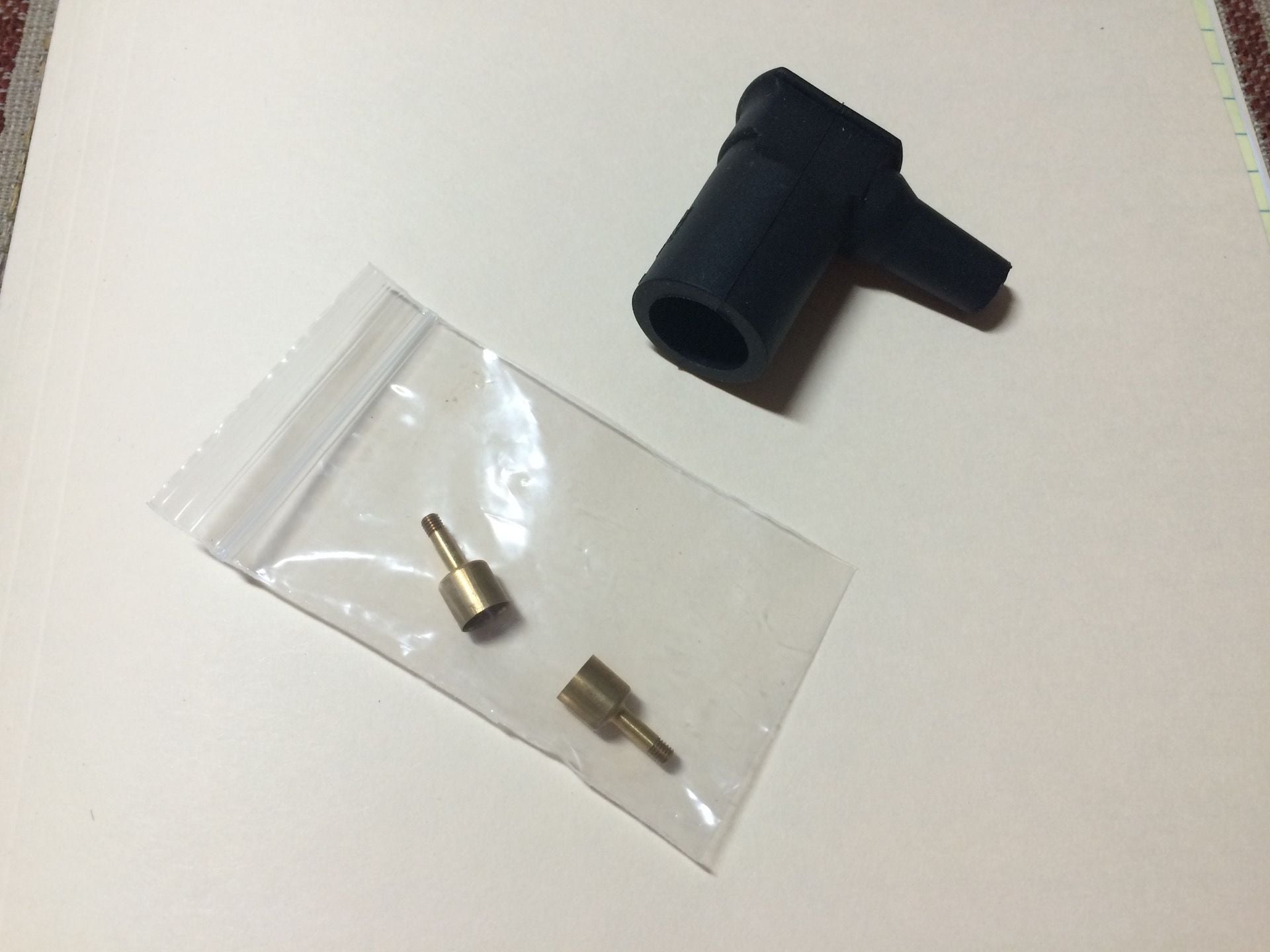
But here is the problem. You cannot buy the connector with the saw-tooth
coupling. They only sell the connector with the M3 coupling. Figures right?
So you have to change the coupling from saw-tooth to M3. The new connector
is less than $6 and the M3 coupling is $1 so not bad. But. The crimp tool is
$325. They got it all figured out.
I checked about 4 independent shops and 1 dealer and nobody had the
tool. Porsche stopped using spark plug wires back in the 90s. Mercedes,
who also used the M3 coupling, probably stopped even earlier.
Fortunately, I was able to drive down to San Diego (2 hr drive) and Kingsborne Wirewerks (whom I purchased the Beru connector from) installed my new
connector in about 5 minutes. Problem solved.
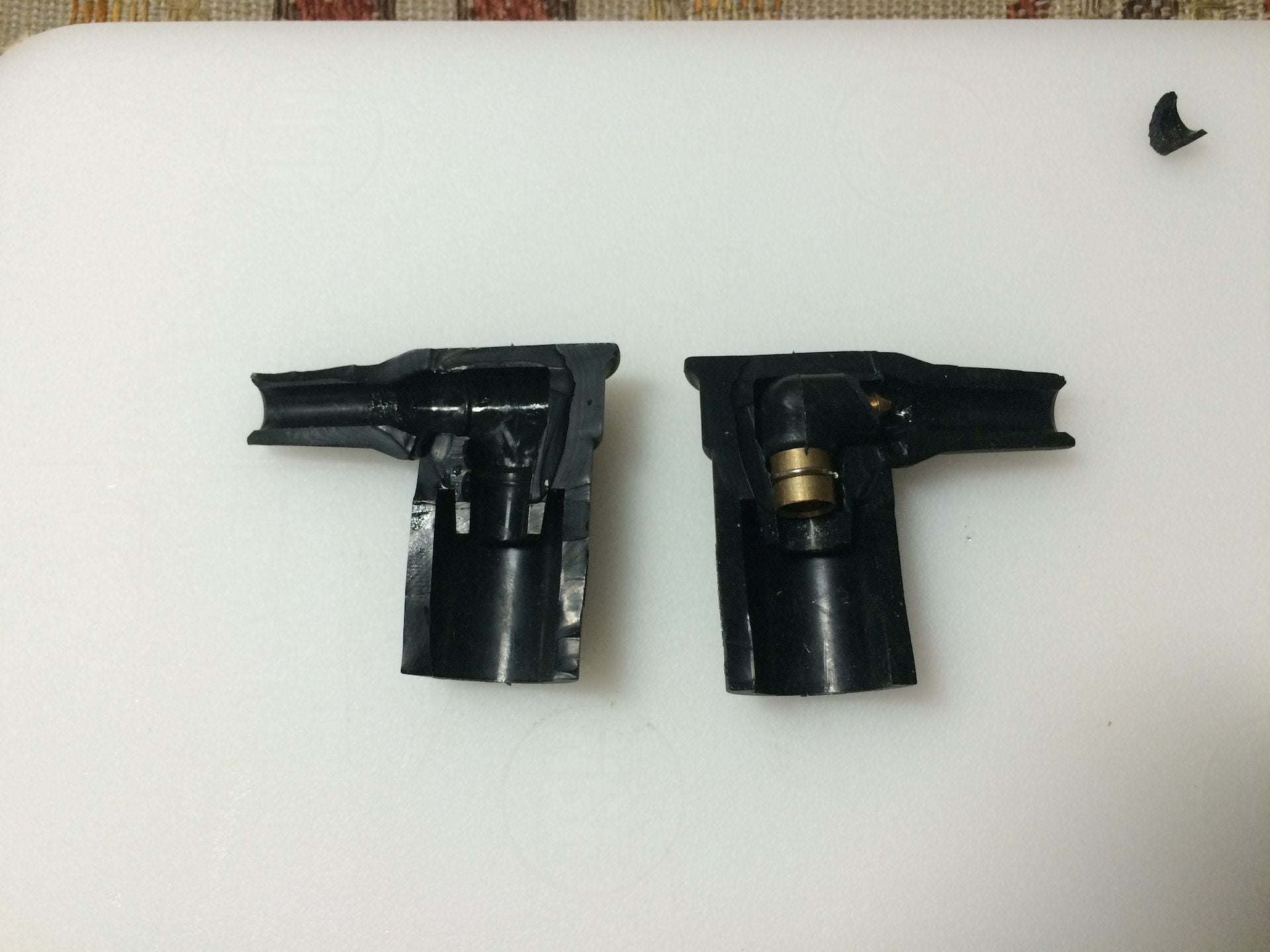
Here is a shot of the old connector cut open and the little saw-tooth coupling
that is inside. Looks like it is formed around the coupling and not inserted.
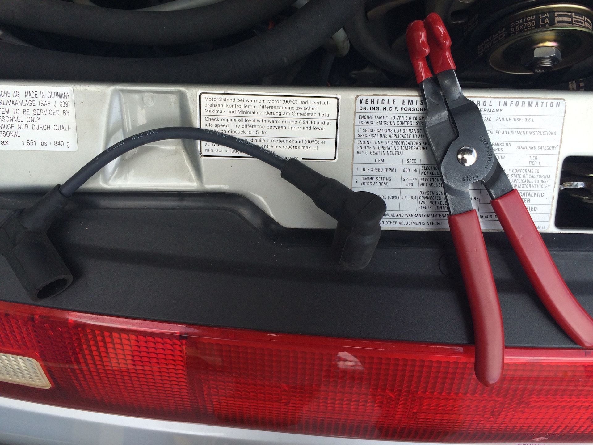
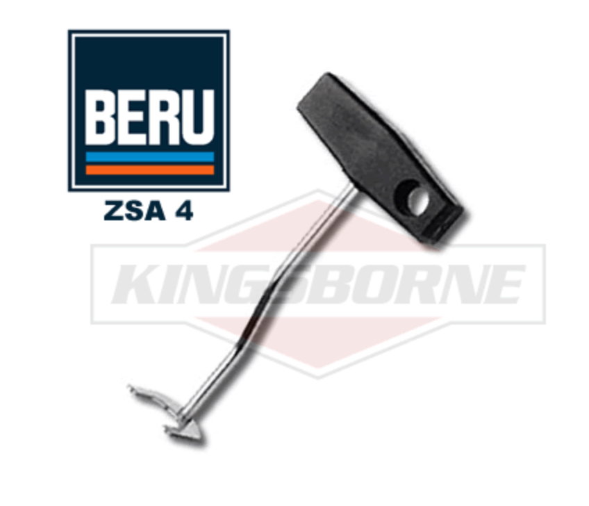
I mentioned earlier that I found a better tool for removing the connectors
on the coil and distributor cap. Yes, you can use your fingers but it can
be pretty hard to get ahold of them for proper leverage to pull them off.
This tool is sold by Beru for actually something else but I found that it is
almost perfect for pulling the connectors.
It is just a little too narrow as it is but by widening the opening to 20mm
I found it is about right. Here a photo of the tool as it comes.
I was working with it today and I believe I will widen it a bit more and then
post a picture of the modification.
Cautions
Because of the saw-tooth coupling being used instead of the M3 threaded
coupling, be careful pulling on the spark plug wires. When installing or
checking an installation push the wire ends together to make sure they
are fully seated. A misfire situation could result from a bad connection.
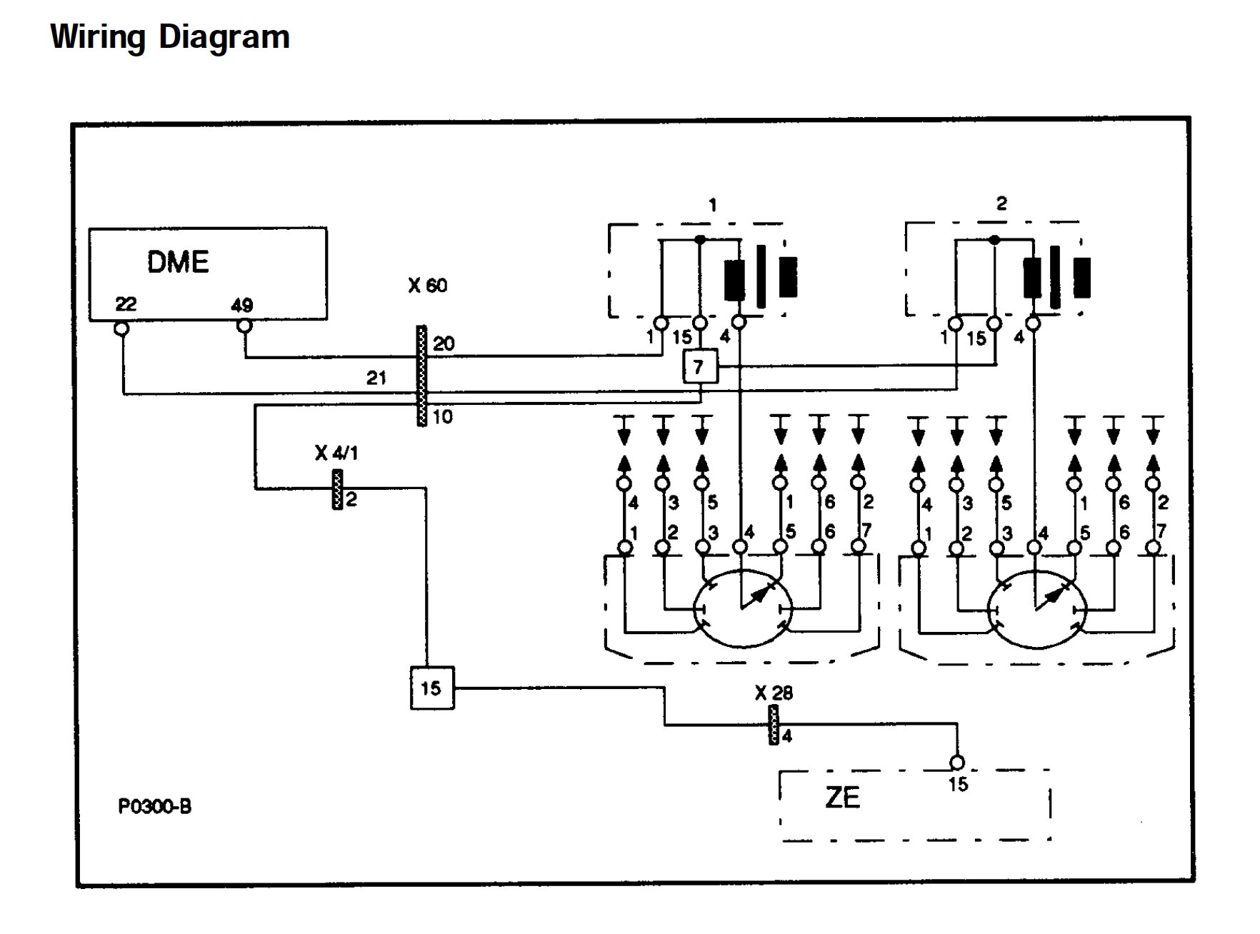
Next, I'm going to start posting up some scope traces from the ignition
system.
This snippet from the previously attached Porsche document shows
the ignition system wiring diagram.
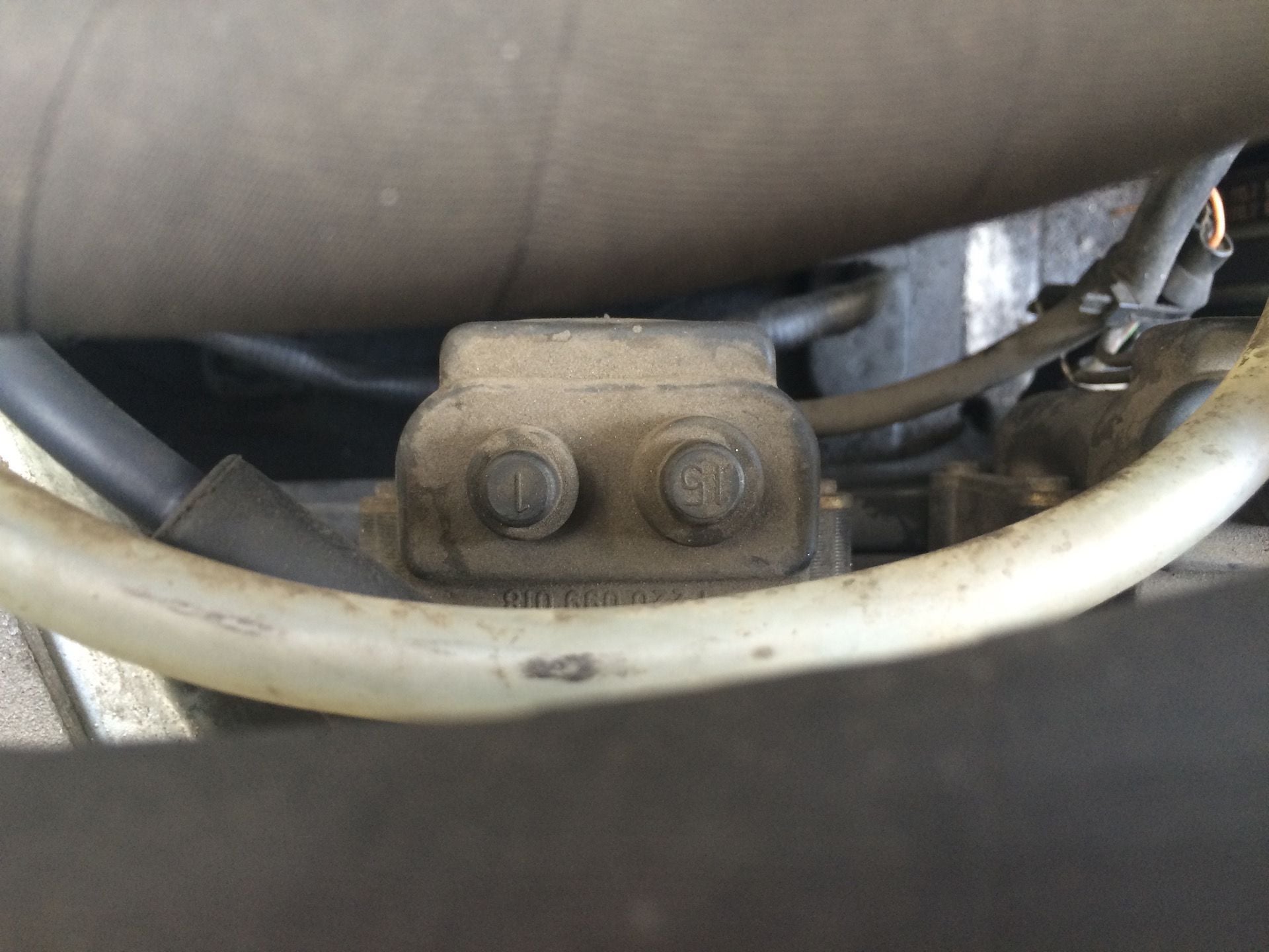
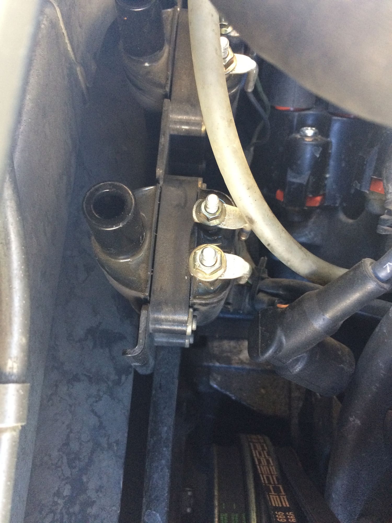
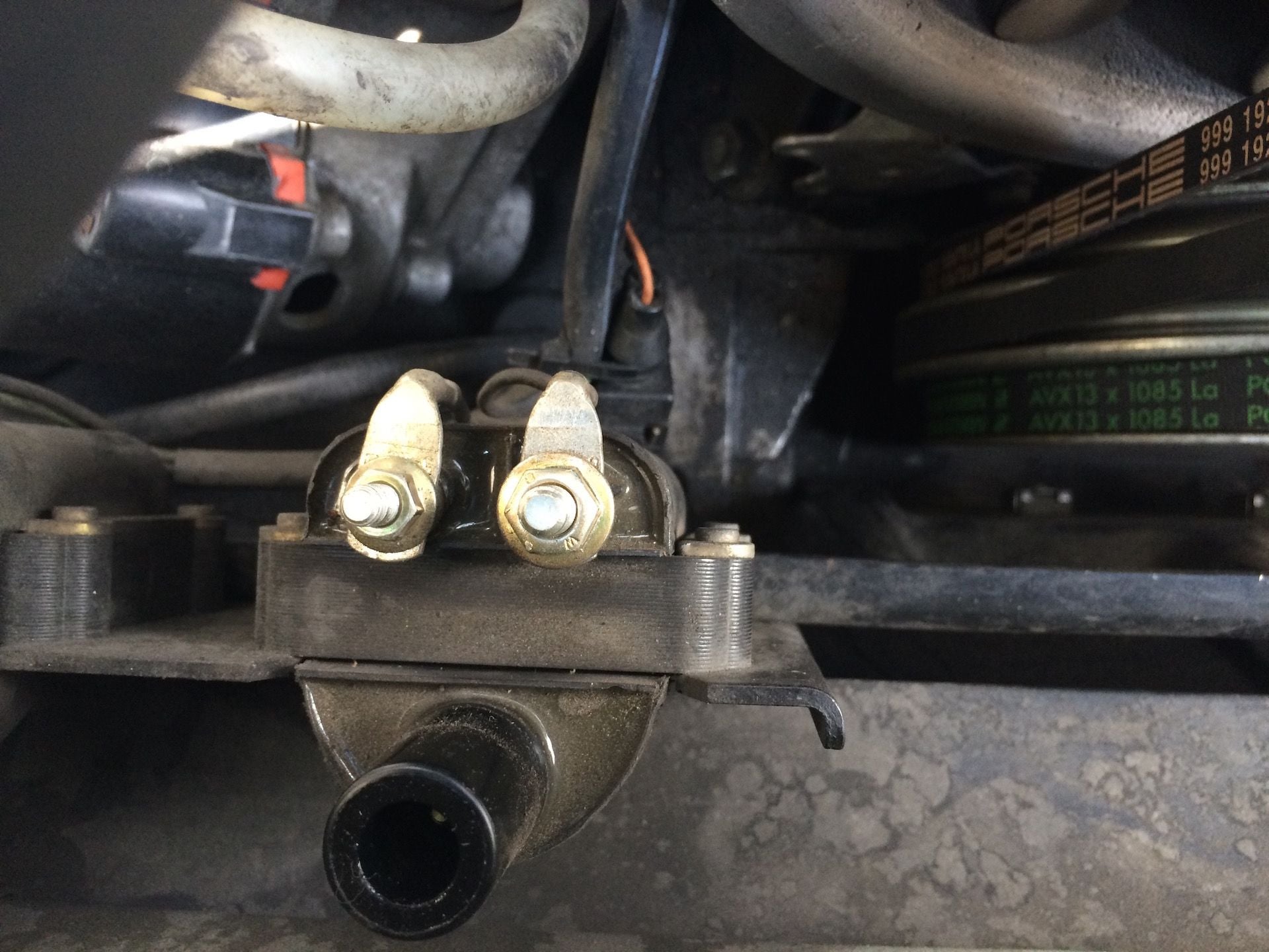
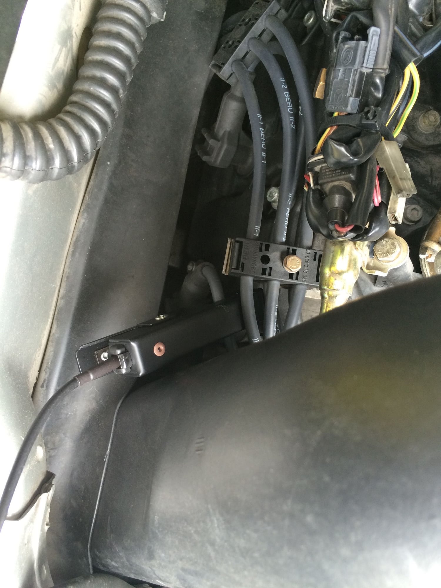
The coils are accessed at the rear of the engine compartment as the
next photos show.
Per the Porsche document, the resistance at the coil terminals can be
checked.
I tested my coils using a Fluke 73 III DVM at 68 degrees F (20 degrees C)
on a cold engine.
For Coil I the measurements were:
0 .7 ohms between terminals 1 and 15 (spec is .4 - .6)
8.2 Kohms between terminals 1 and 4 (spec is 5 - 7.2)
For Coil II the measurements were:
0.7 ohms between terminals 1 and 15 (spec is .4 - .6)
8.02 Kohms between terminals 1 and 4 (spec is 5 - 7.2)
The results are just a little bit high but not far off. I would not fail the
coils at this point. More definitive will be coil ramping tests and spark
burn duration.
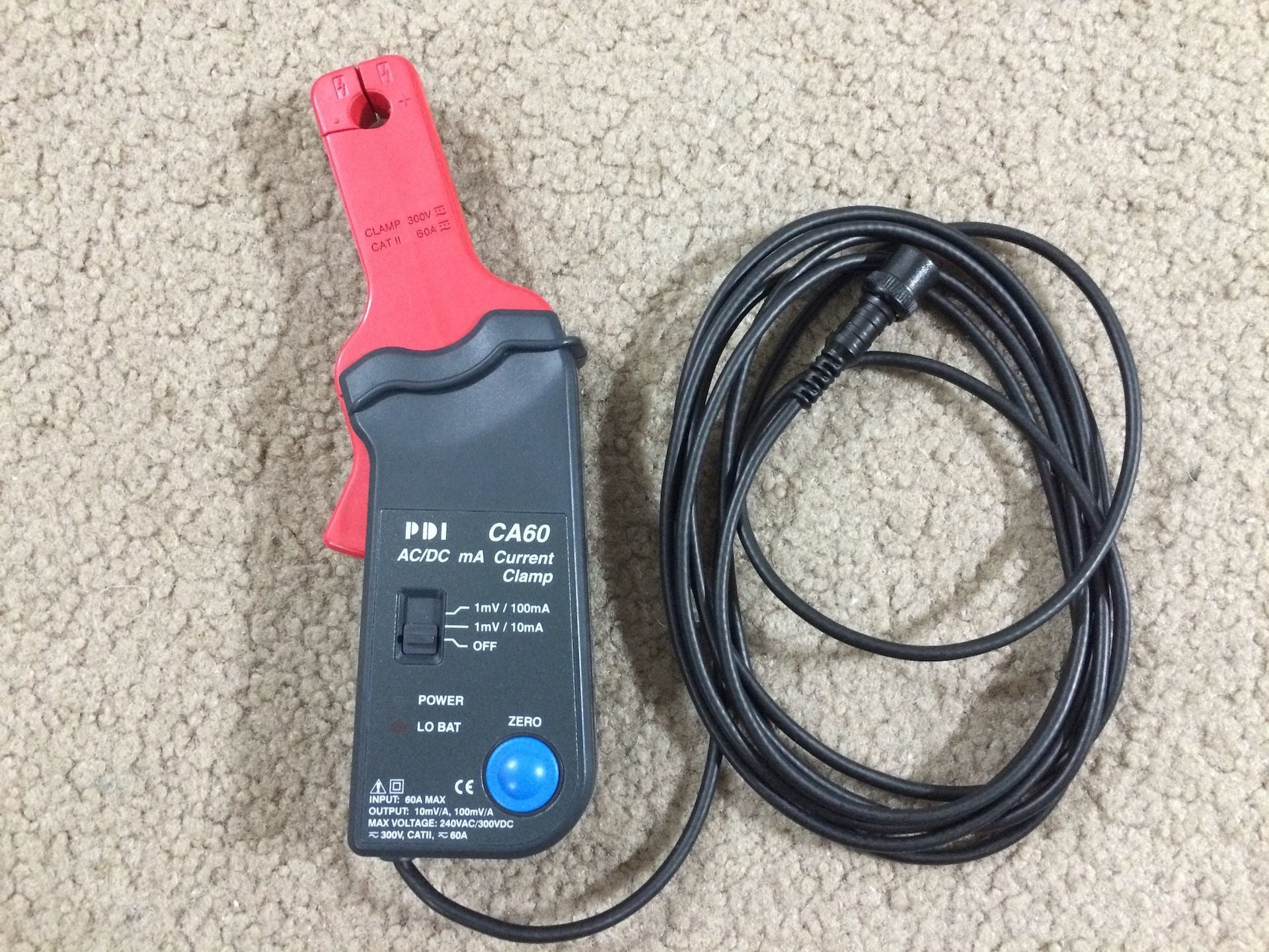
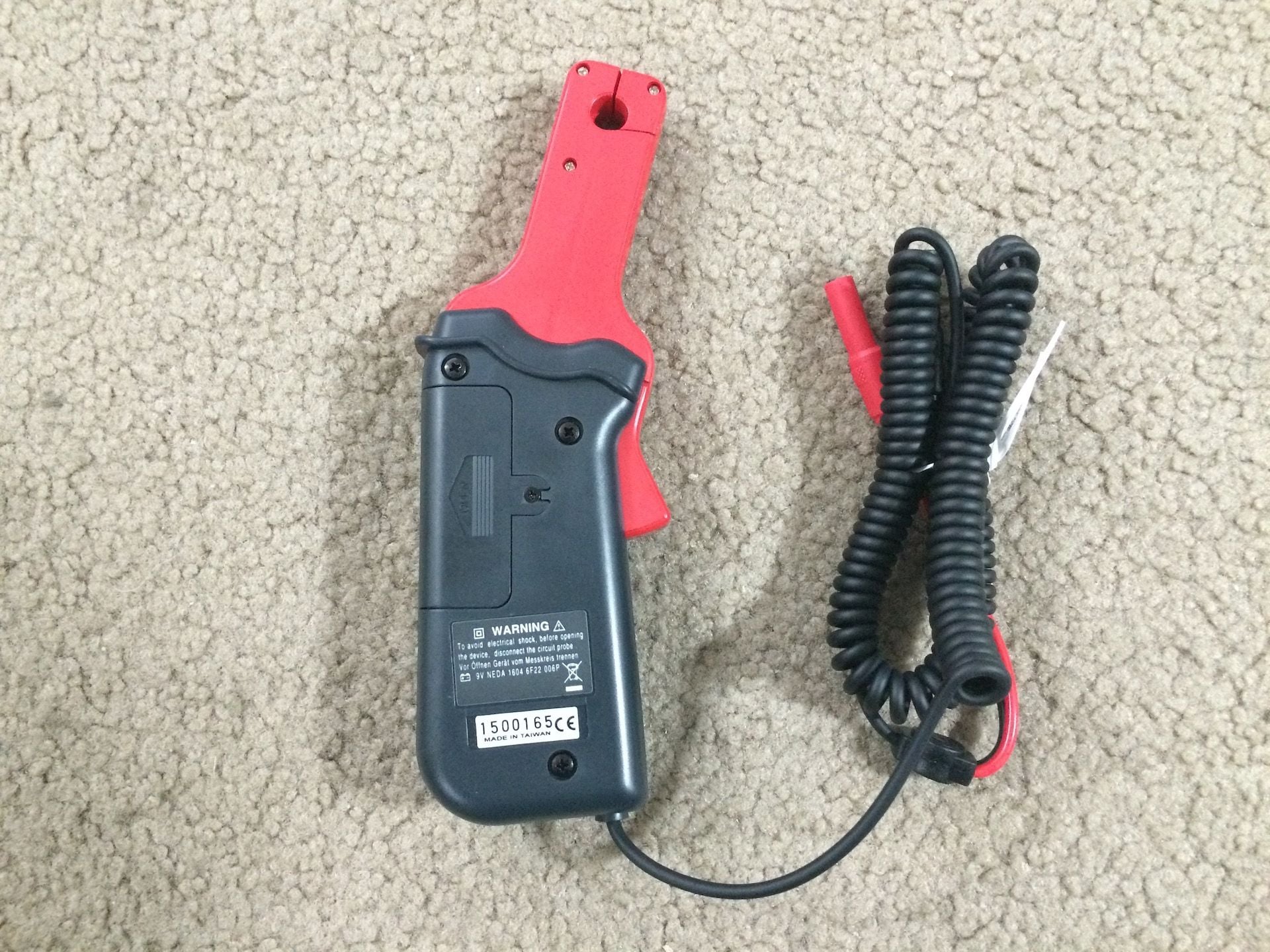
To perform a coil ramp test will require a low amp current probe and
the scope.
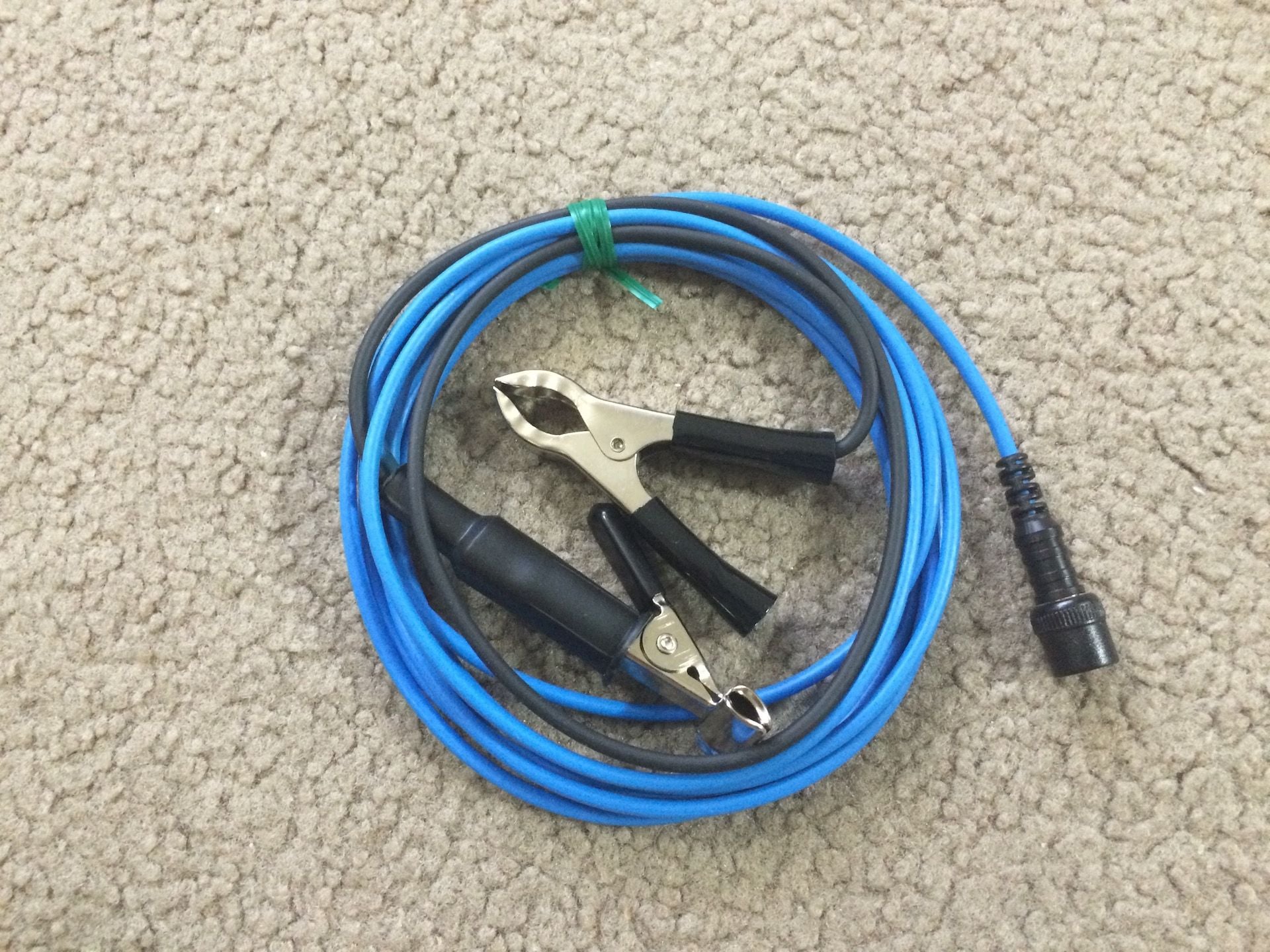
Here is photo of my low amp current probe. I purchased it from AESwave
and had it custom modified to use a 10 foot shielded BNC test lead with
a shielded BNC connector. The cable is long enough to be able to sit in
the drivers seat with the scope and control the throttle and ignition.
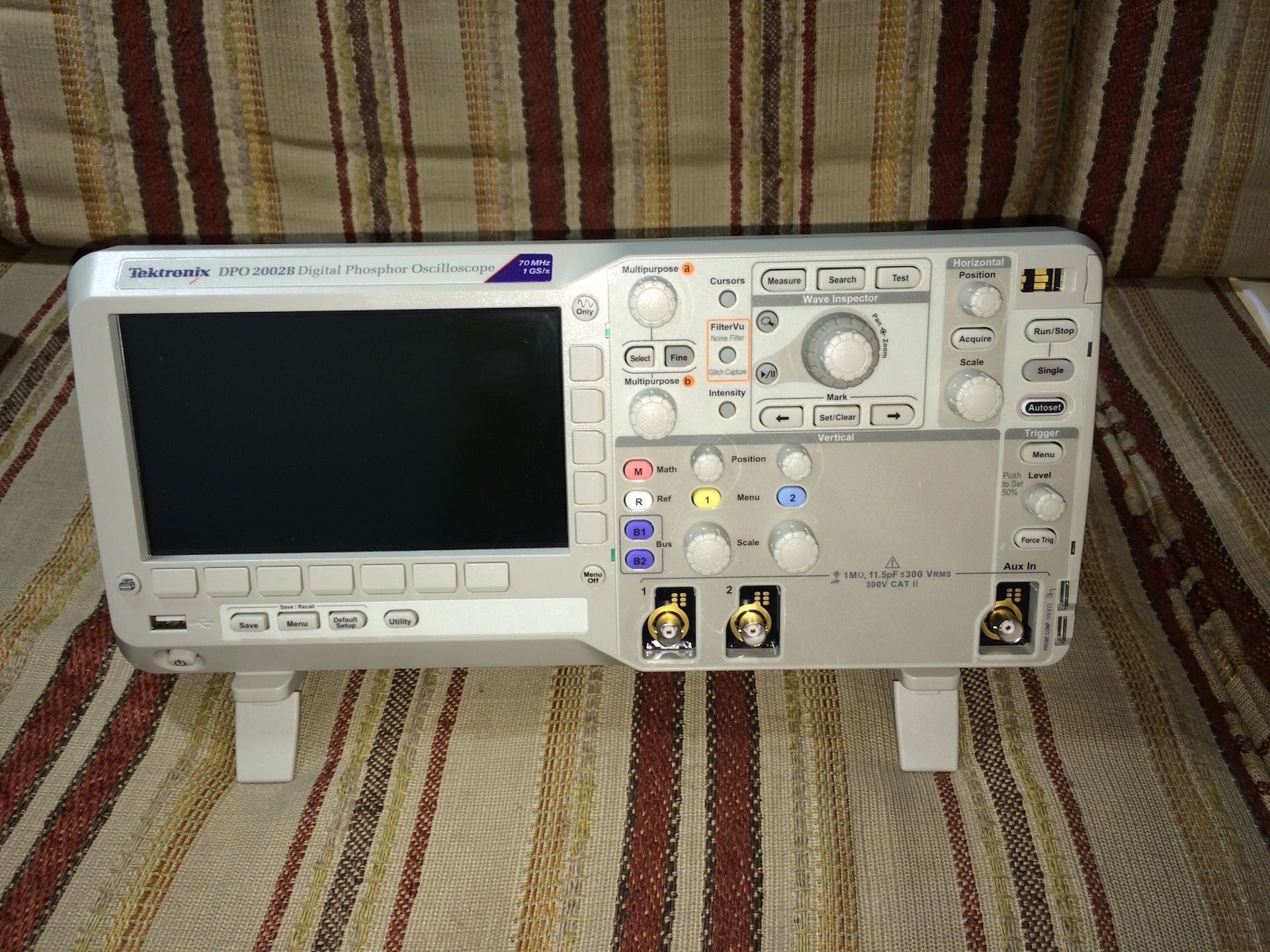
And here is my Tektronix scope. This is not an automotive scope so
does not have all the bells and whistles that a Pico scope has but it
suffices for my needs at this point. Nevertheless, one day I'm sure I
will upgrade to a scope with more capability when I'm ready.
This scope was purchased from Techni-Tool in PA from Zachary Savana.
Thanks Zachary!
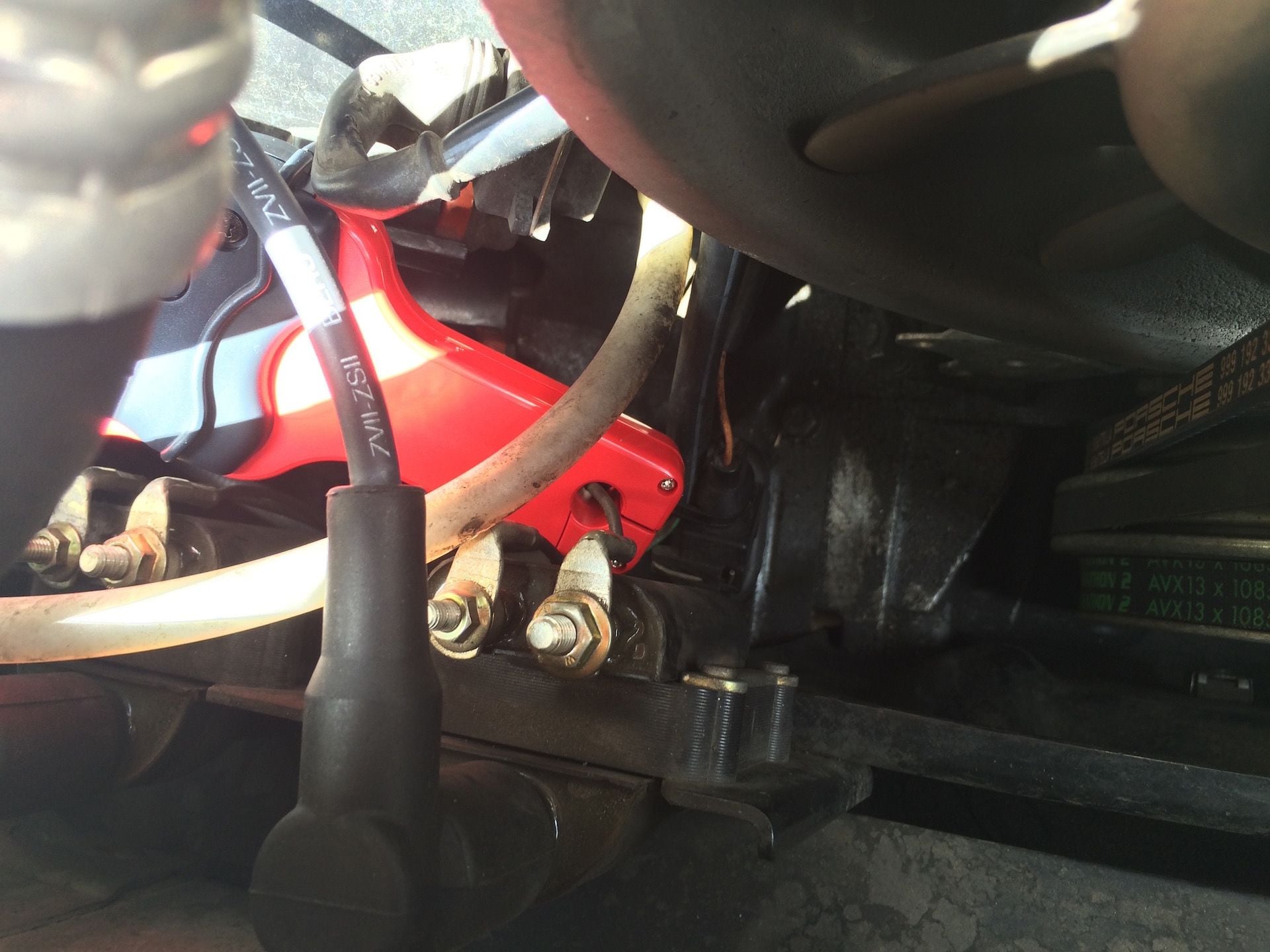
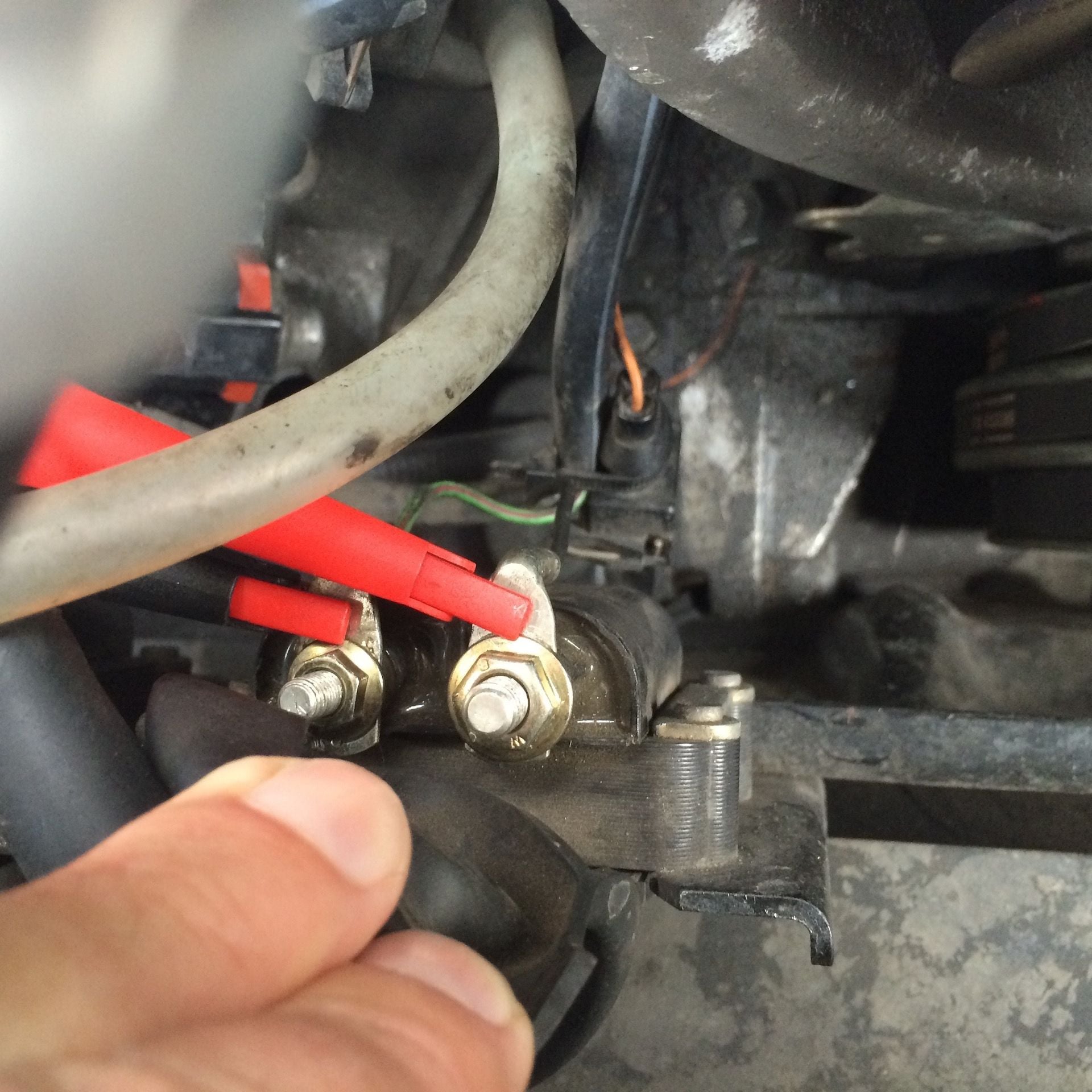
In this next shot I have connected the probe to one of the coil leads.
In this case it is the terminal #15 lead which is switch-controlled
positive downstream from battery (from ignition switch). Remember
that current is the same everywhere in a series circuit so you can connect
to the terminal #1 or #15 leads and get the same results.
Two things to mention about using the low amp current probe: always
zero the probe whenever moving it to a new test point. Failure to do
so will result in a false measurement. I spent some time trying to
understand why current on one coil was peaking at 5 amps and peaking
at 7 amps on the other and was intermittent. The second thing is
to remember to return the switch to the off position when done or
it will run down the battery overnight. The led is very dim and it is
easy to overlook this step when putting the probe away.
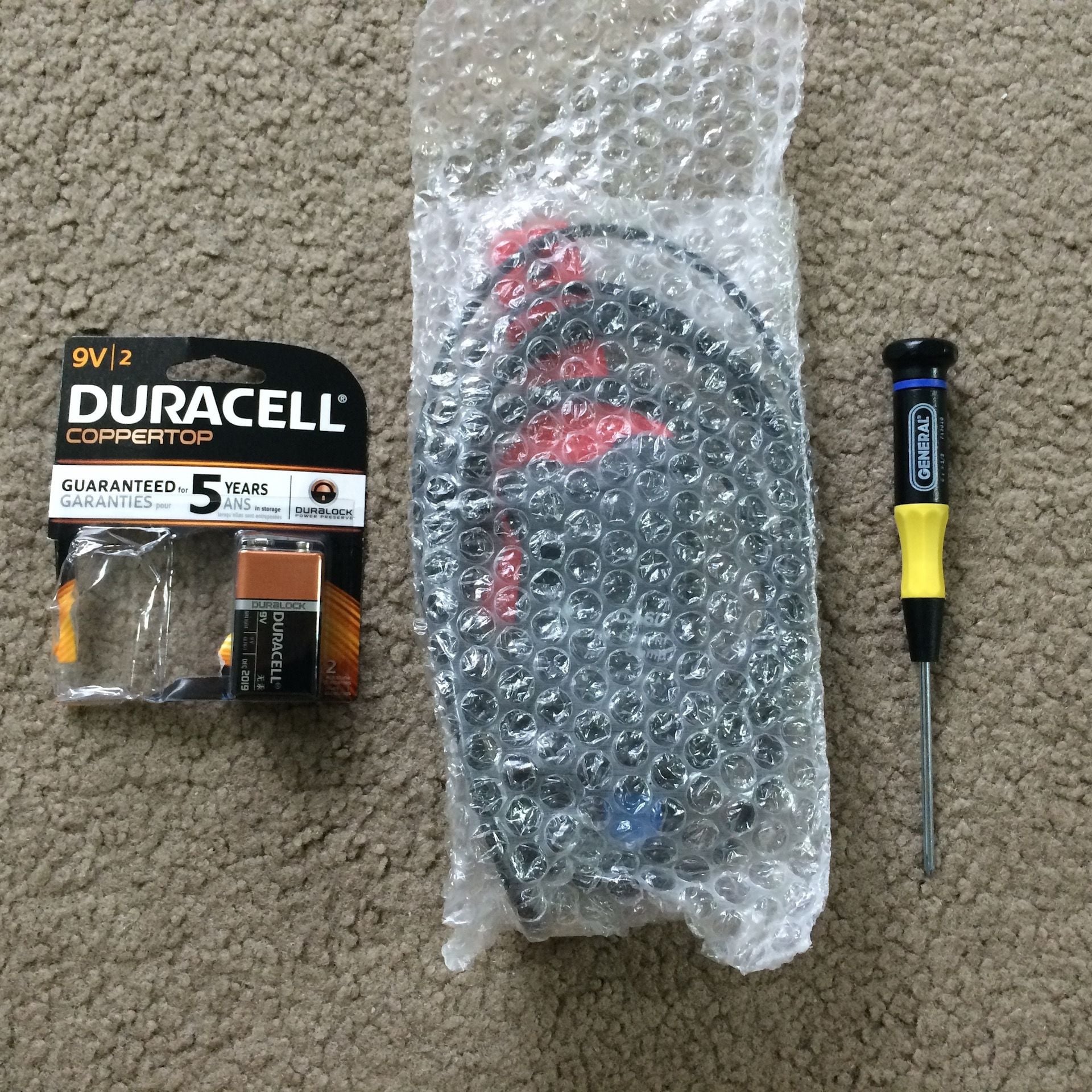
When you do have to change the battery, you have to remove a very
tiny screw on the back to get to the 9v battery inside. I had to get
a screwdriver just for this and now I keep it with the probe along with
a spare battery.
The Phillips screwdriver is size 0.
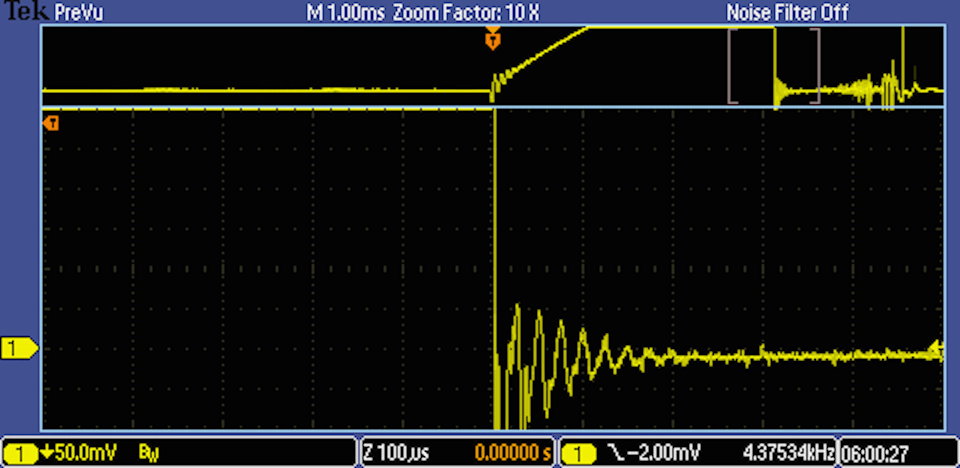
Next up is coil ramping tests.
Last edited by bruce7; 07-28-2015 at 03:18 PM.
Reason: clarify probe connection
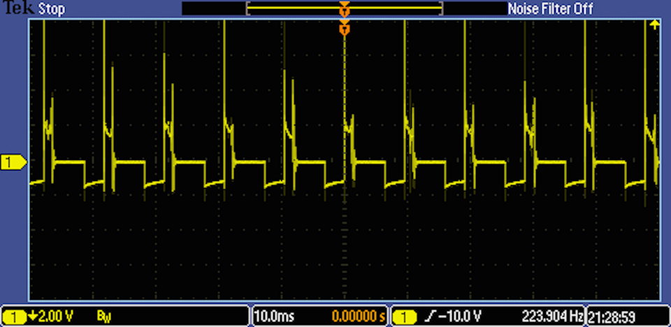
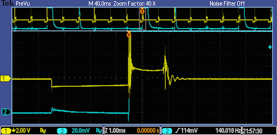
The coils, to best of my knowledge, are the original coils and have at
the time of testing 112k miles on them.
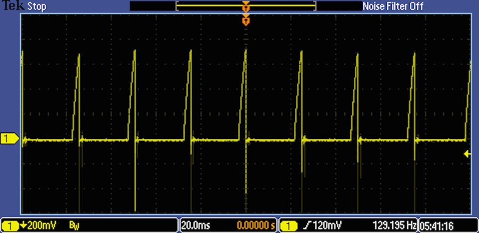
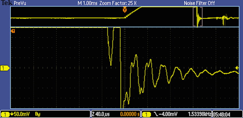
The dwell period for the coils is 3ms and remains consistent at all
speeds and loads observed.
The current peak at the end of the dwell period is 7 amps
and is consistent at all speeds and loads observed on both coils.
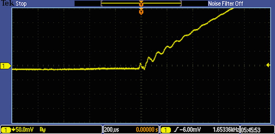
At the On Signal, there are current oscillations which last about
.5ms until the magnetic field induced in the secondary windings
is overcome. At that point the current ramps to the end of the
dwell period in a linear fashion. The oscillations in Coil II are a
bit larger which may indicate a bit more resistance. The oscillations
are regular and the decay normal without any irregular humps that
might indicate a problem with the secondary windings.
The Off Signal is nearly vertical which indicates the circuit is shut
off quickly and completely. This indicates the driver circuit is
behaving normally. The ringing (oscillations) after the current is shut
off is the draining of the remaining coil energy and appears regular
and decays in a normal manner.
Under load the coil current waveforms remain consistent and stable
under all observed speeds and loads.
The coils are looking good to remain in service but I'll do a spark burn
duration test next to check coil output (energy) to sustain the burn.
Caveat: I have not seen or tested a new coil so have no comparison
that I can offer. Also, as I may have mentioned, I'm not a automotive
tech but an enthusiast that is teaching himself how this works so
my analysis should be considered in that light. If someone has something
to add or differ with me on this please jump.
Reference Material
At this point it might be a good idea to post up some reference material
that I've collected. There is a ton of stuff on the internet you can find
about ignition waveforms and this is just a few of the many articles that
have been written on the subject.
In the reference material in the previous post is an article on spark burn
time duration. I'm focusing on this key parameter as it is thought to be the
most important measurement in the spark waveform due to the fact that
the burn duration time can be affected by a number of factors. The burn
time is directly proportional to the spark firing voltage. The higher the
spark firing voltage the shorter the burn time. This is because if a lot of
coil energy is used in the spark firing it leaves less energy to sustain the burn.
Capturing spark burn waveforms can be done at 3 points in the ignition circuit:
1. on the primary voltage side (across coil terminals #1 and #15)
2. on the secondary voltage side (on the coil wire)
3. on the secondary voltage side (on an individual spark plug wire)
The best signal is found on the primary voltage side. Next best is on the
coil wire and finally the spark plug wire.
A different setup is used depending upon where the test point is located.
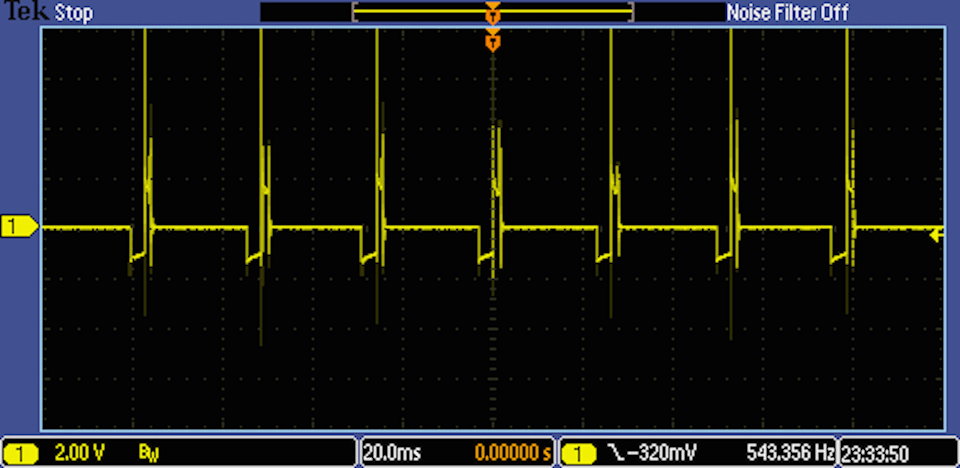
On the primary voltage side, a primary voltage test lead is used together
with alligator clips and a 10:1 attenuator. It is necessary to attenuate the
signal because the voltage peaks are around 350v and the scope cannot
handle over 300v.
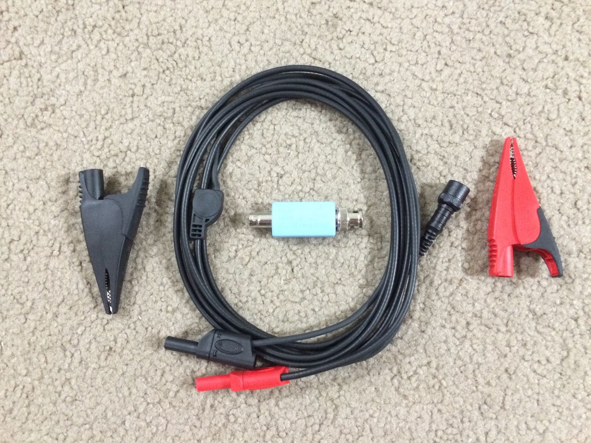
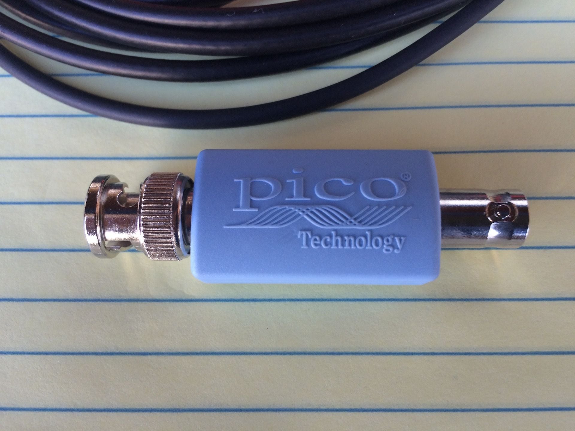
Here is the cabling setup. A shielded cable with BNC for connection to
the scope, 10:1 attenuator made by Pico, and alligator clips made by Fluke.
Closeup shot of the attenuator.
Showing how the connection is made at the scope.
Showing how the connection is made at the coil terminals.
Similar to the coil ramp tests we want to take measurements under 3 scenarios:
1. at idle
2. at 2000 rpm
3. under snap-throttle determine the min and max durations
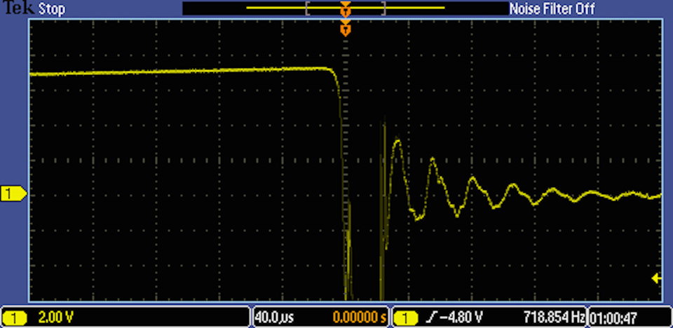
Idle Coil II
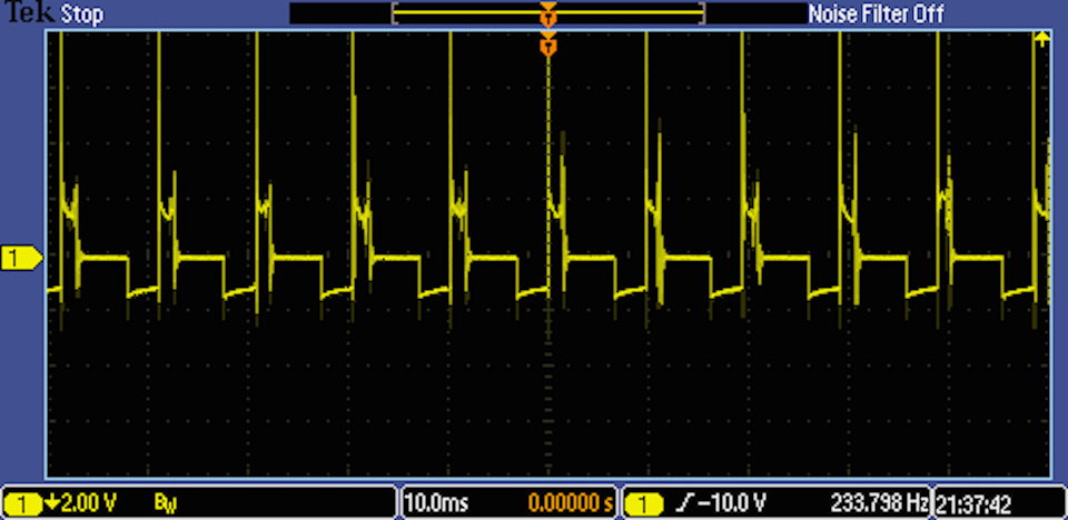
First I want to show a parade of all the cylinders.
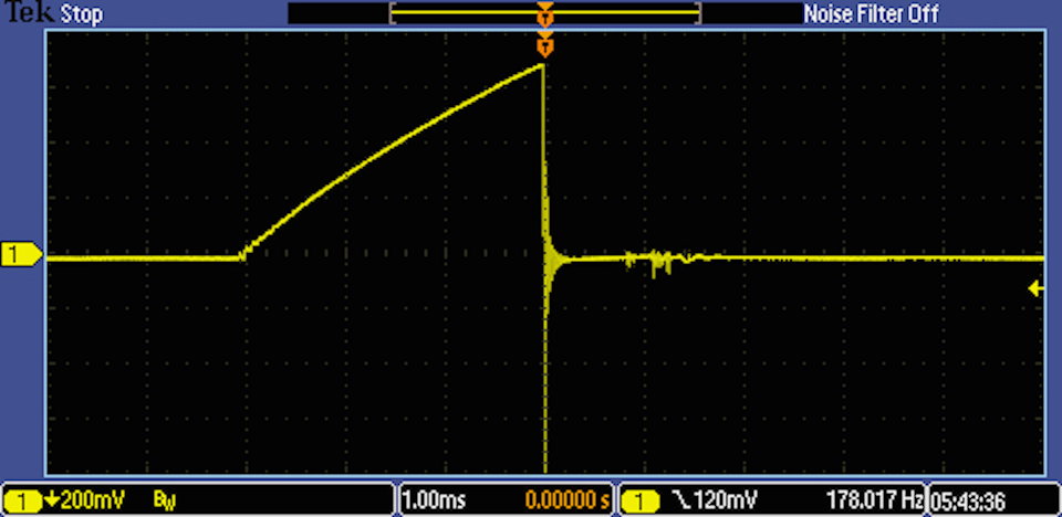
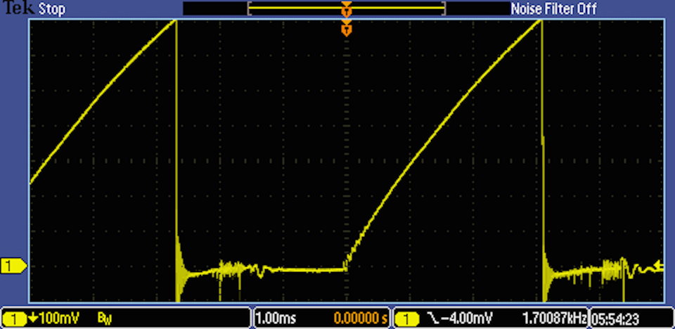
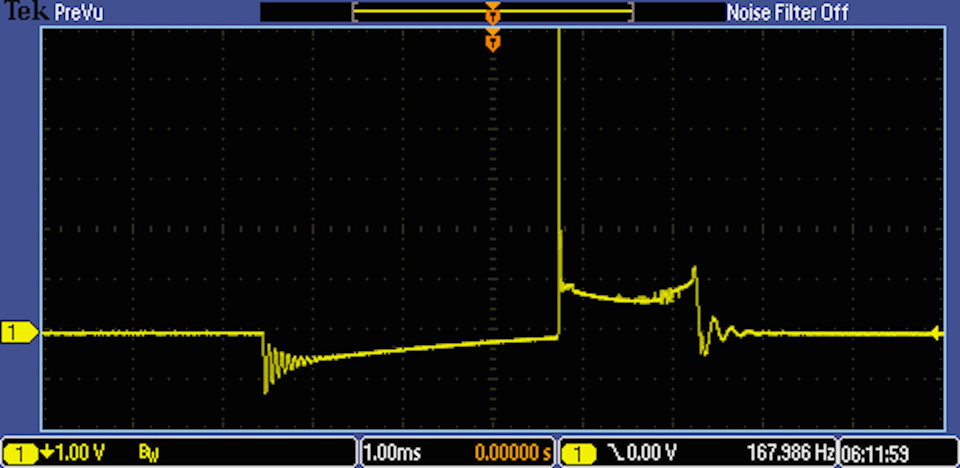
Here is a typical single cylinder ignition waveform.
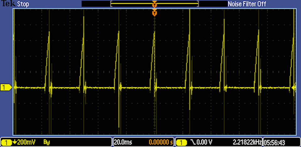
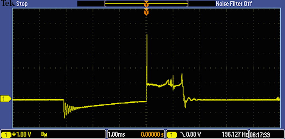
Next is a shot showing the 350v peak. This is normal and is generally
off the screen. I made it visible here to show where it measures.
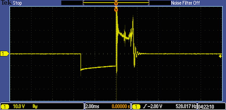
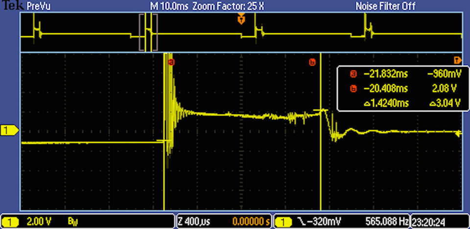
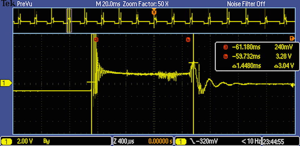
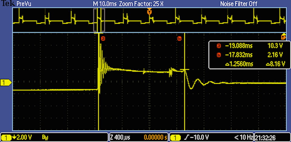
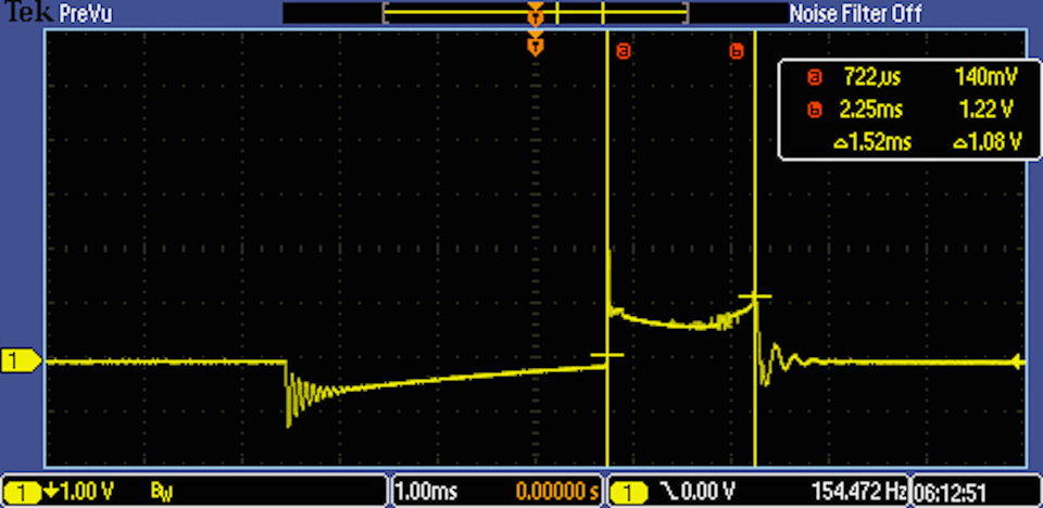
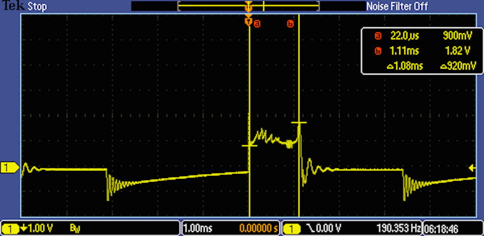
Next are a couple of example single cylinder spark events. The burn
duration time is measured using cursors. Here it is 1.4240ms (the
distance between cursor a and cursor b).
For Coil II found the range to be 1.20 - 1.45 ms for an average of 1.34 ms.
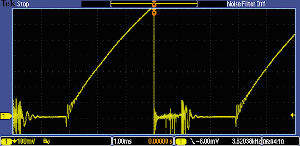
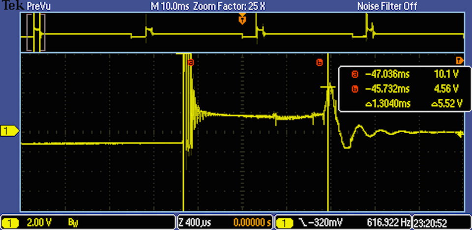
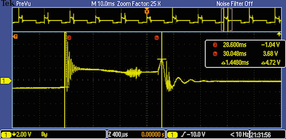
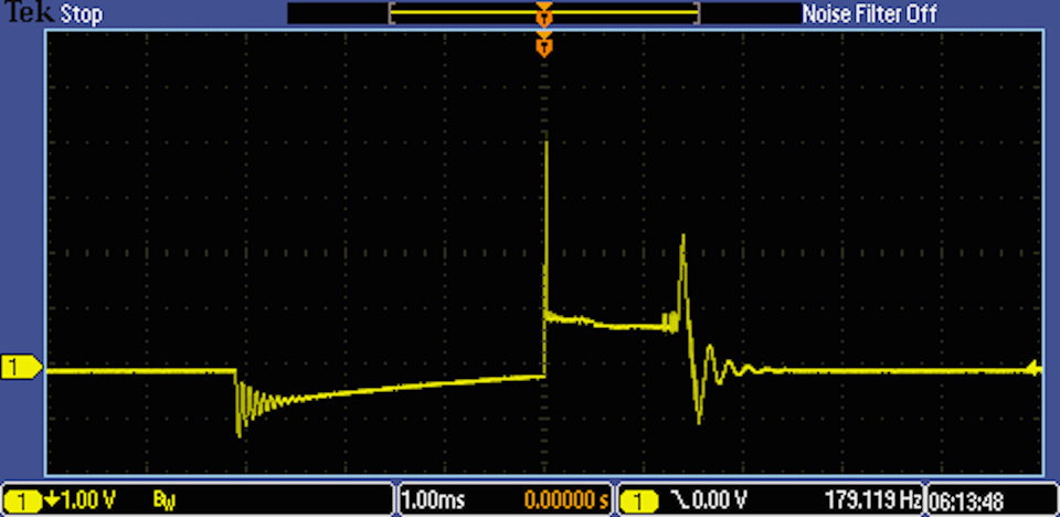
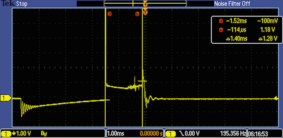
Idle Coil I
Here are a couple of example spark burn duration times for Coil I.
For Coil I the average burn duration time was 1.40 ms.
The screen display looks different because I didn't measure the duration
at the time of capture but instead did it just now by recalling the waveform
into the scope and using the cursors to measure.
2000 rpm
This test has been moved to the following post.
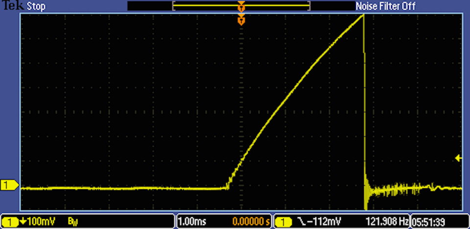
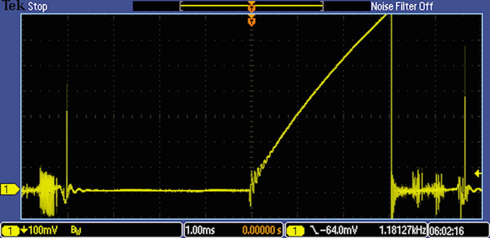
Snap-Throttle
Here we want to determine the min and max duration under acceleration and
deceleration simulated by a snap-throttle. Under acceleration we would expect
longer burn times as the air/fuel mixture is richer and under deceleration the
burn times should be shorter.
This test is a little tricky as my scope does not have data-logging so I have
to try and trigger the scope manually.
Right now I only have test results for Coil II.
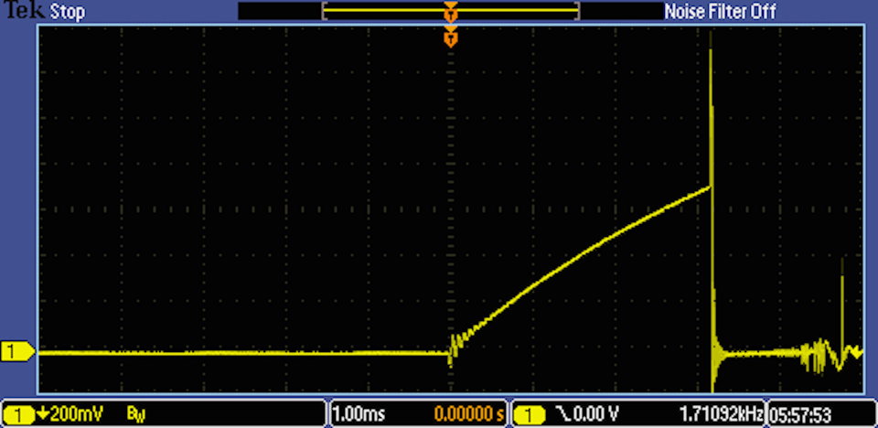
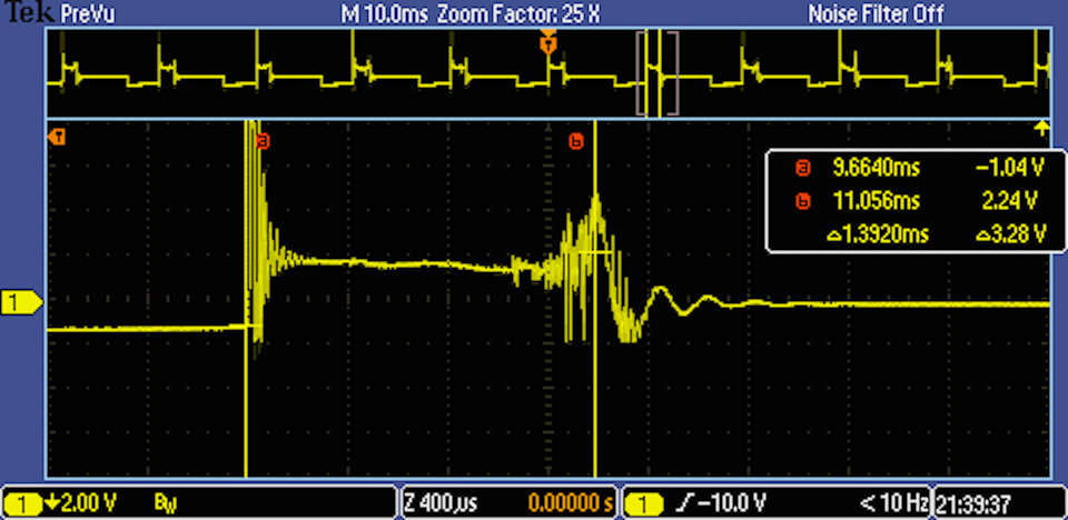
Here is the minimum spark burn time duration I found.
And here is the longest spark burn time duration I found.
The .688 ms spark burn time duration is very short and according to the
reference document indicates a problem. Possibilities are low coil energy
and lean mixture (no enrichment). It could be that the fuel was cut off
under deceleration and this is normal. Needs further investigation. The
coil energy seems sufficient otherwise.
Next up is the 2000 rpm test results.
Last edited by bruce7; 07-21-2015 at 03:43 PM.
Reason: moved 2000 rpm tests to next post
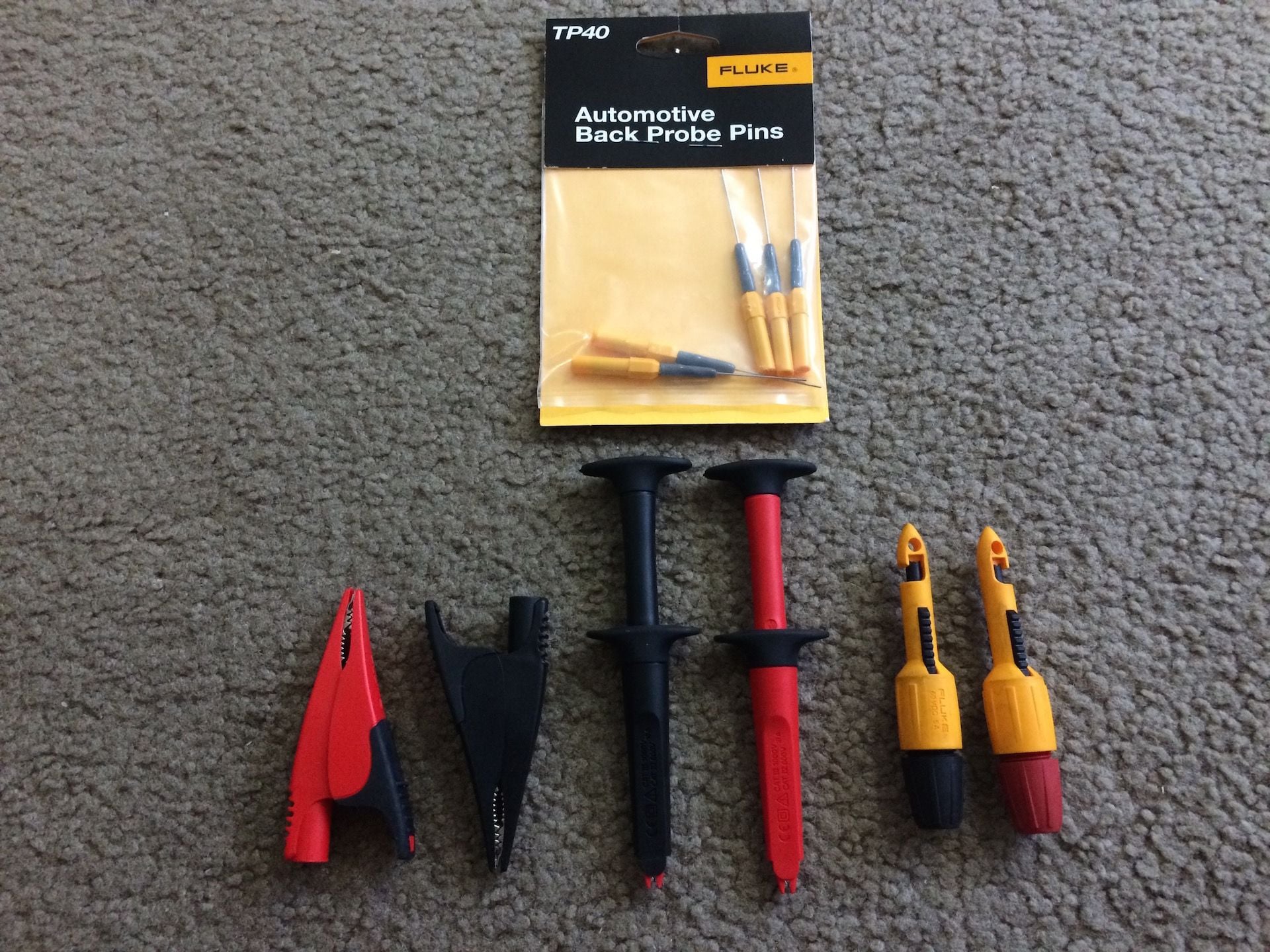
There are a number of different probes that can be used to connect to
the coil terminals. The best one to use is the one that gives the most
secure connection, best signal and least damage to the conductor.
Here is a photo of probes I've collected that I could use.
On the previous tests I used the large alligator clips but this time I'm
going to use the retractable alligator clips. I like how they can be wedged
under the lead for a secure connection.
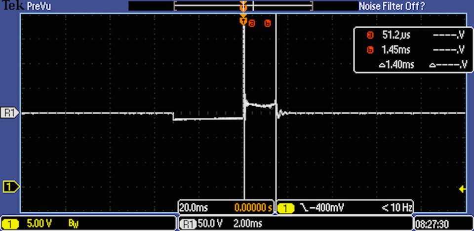
2000 rpm Spark Burn Duration on Coil I
Here is a parade of waveforms captured at 2000 rpm.
I sampled 6 waveforms. The values were: 1.32, 1.43, 1.38, 1.38, 1.45, 1.26 ms.
The min was 1.26, the max 1.45 and the average 1.37 ms.
Here is the min sample measured.
And here is the max sample measured.
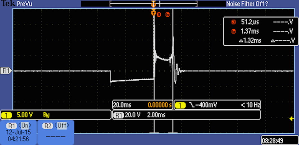
2000 rpm Spark Burn Duration on Coil II
Here is a parade of waveforms captured at 2000 rpm.
I sampled 5 waveforms The values were: 1.56, 1.46, 1.43, 1.39, 1.48 ms.
The min was 1.39, the max 1.56 and the average 1.46 ms.
Here is the min sample measured.
And here is the max sample measured.
The spark burn duration times for both coils looks good. The average
for Coil I is about .1 ms shorter than for Coil II and this seems to be
consistent with other testing I have done.
Videos of Waveforms
I took two short videos of each coil under test and posted them on
YouTube. They show the voltages as they change in realtime on
the scope. I took them with my iPhone as the scope does not have
data-logging or the capability of generating a playback movie.
Coil I
Coil II
Using a Trigger Sync Probe
Just want to briefly touch upon the use a trigger sync probe. This probe
can be used to trigger whenever one spark plug is fired. Then given the
engine firing order you can tell which waveform belongs to which cylinder.
This can be useful when troubleshooting a problem with one cylinder.
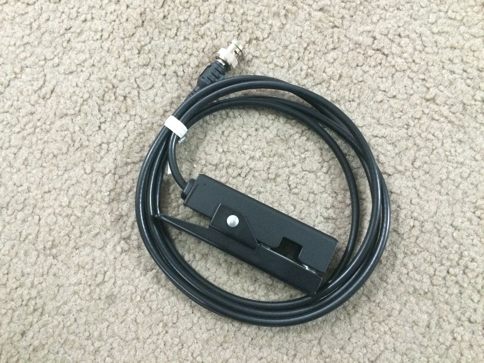
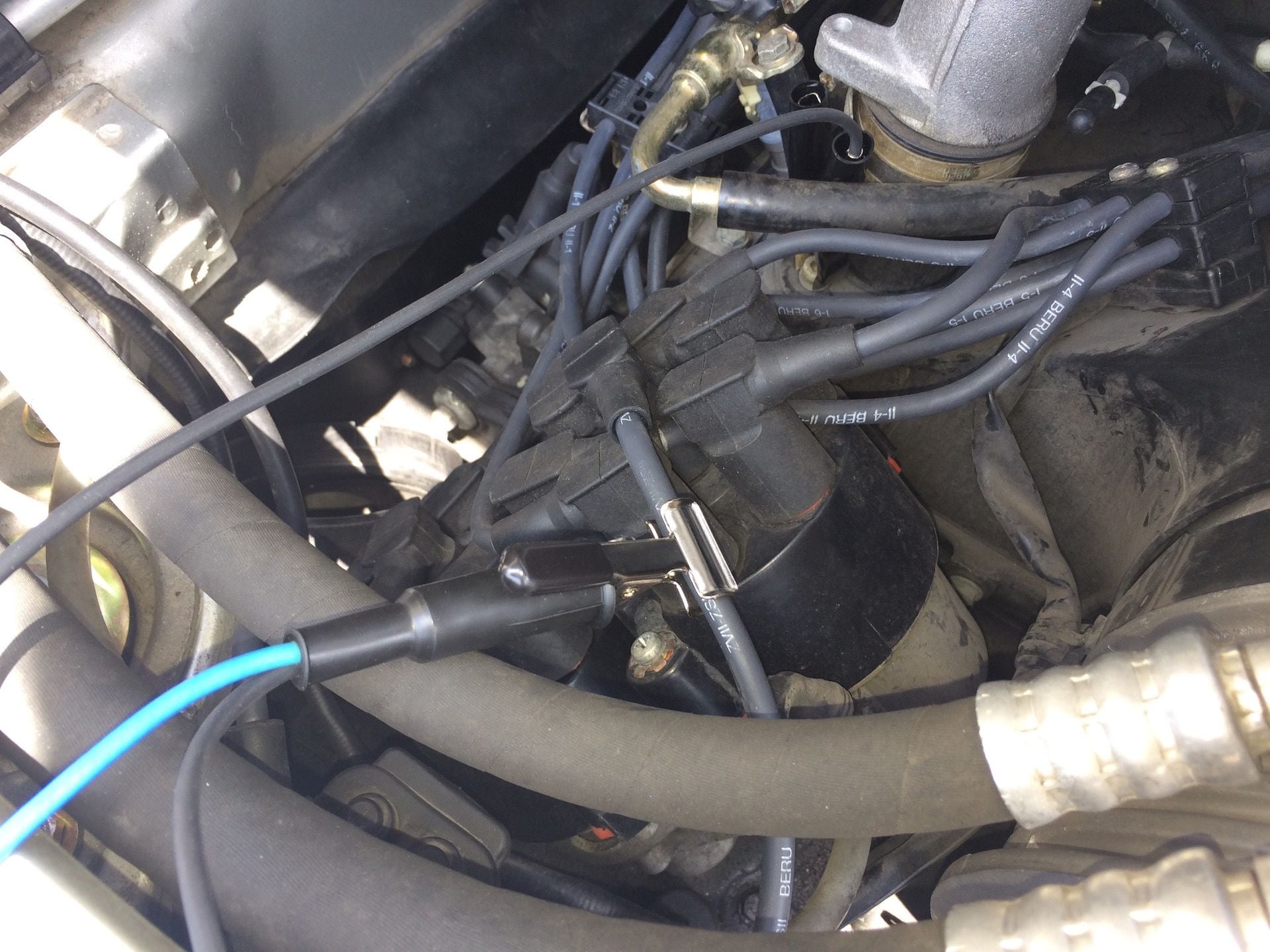
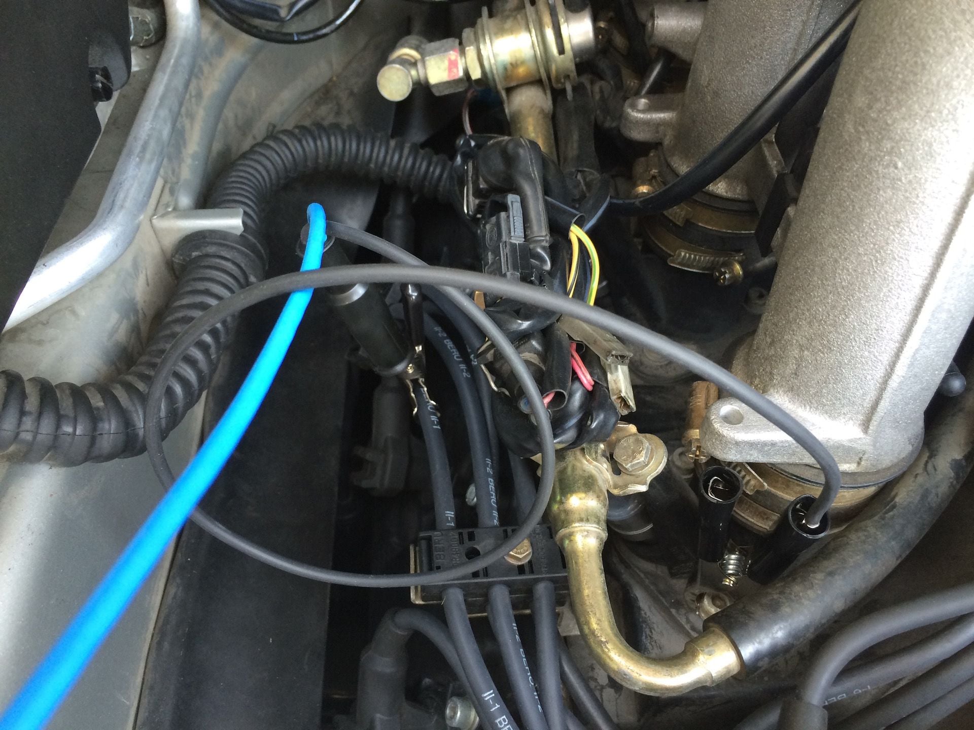
Here is a shot of the trigger sync probe I purchased from AESwave.
Here is a shot of the trigger sync probe attached to spark plug #1 upper wire.
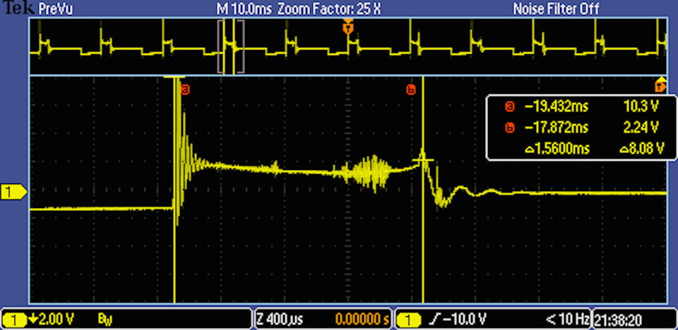
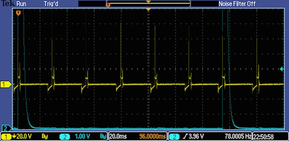
Now here is a screen shot using the trigger sync probe.
I didn't quite position the sync probe carefully enough and it looks
like it is picking up the firing signal for cylinder #2 as well as #1.
But you can tell where the trigger occurred and given the firing order
and number of cylinders you can tell which cylinder is which.
The trigger sync probe was attached to channel 2 on the scope and its
signal is shown in blue. It can also be attached to the aux channel on
the scope if you don't want to see the trigger or if you need to use
channel 2 for something else like the low amp current probe.
Here is another capture taken a couple of months prior after the caps/rotors were changed
that gives a better example perhaps.
Last edited by bruce7; 07-24-2015 at 02:01 PM.
Reason: added another capture with trigger sync probe
The procedure for checking secondary ignition waveforms is essentially
the same as with the primary ignition waveforms but using a different
test probe setup and test point location.
This shot shows the secondary induction pickup which I use purchased
from AESwave. It has a large alligator clip used to ground the scope
to the engine and an induction pickup which clamps around a coil or
spark plug wire. I had mine custom made to include a 10 foot shielded
BNC cable with a shielded BNC connector at the scope end.
The probe is shown attached to the coil wire and the ground clamp is
attached to an intake manifold bolt.
Here is a shot of the probe attached to a spark plug wire.
In the measurements below, the probe is attached to the coil wire.
Coil I Spark Duration Burn Times via Coil Wire
This shot is a random cylinder at idle.
This is the same cylinder at idle with cursors to measure the burn time.
This is at 2000 rpm. No cursors here but it looks to be about 1.28 ms.
And this is under a snap-throttle.
Coil II Spark Duration Burn Times via Coil Wire
This is at idle.
This is at 2000 rpm. Again no cursors but looks to be about 1.26 ms.
And this is at snap-throttle.
So this pretty much concludes the spark burn duration testing.
We've looked at the ignition waveforms from the primary side of
the ignition circuit and on the secondary side. Results are consistent.
The system is functioning pretty well and in fact the car is running
better now than it ever at 112k miles than when I bought it at 43k miles.
But there is still some more testing we can do to keep tabs on things,
such as resistance in the circuit, so the next item on the agenda is to do
voltage drop testing of the ignition circuit.
 02-19-2015, 11:56 PM