Wiring help needed - rear fog space conversion to extra brake lamp
 07-14-2013, 11:39 PM
#1
Rennlist Member
Thread Starter
The title says it all!
I'm trying to use the potential space where the rear fog lamps would be to add an extra pair of brake lamps.
I'm doing an LED conversion so I can choose whatever base I need and then try to retrofit into the current blank plugs.
[I was apparently stupid enough back in 2008 to pass on a wire harness for <$10]
Searching for information on this topic shows some people using a GM aftermarket base with 3 wires.
I cannot find any additional information!
Are 3 wires needed or would 2 be sufficient?
And, most importantly, what would be the best way to wire?
I'm thinking about tapping into existing brake light in a parallel circuit. (Therefore proving that 2 wires would be sufficient.)
As both lights will be LED the current draw (& resistance? It's been a long time since I had to think about these topics!) should be far less than even one set of incandescent.
Am I missing something?
 07-15-2013, 01:58 AM
#2
You're the right track, take your new bulb sockets and connect them to the existing brake lights, use self tapping connectors and you're done, without cutting the wires. What type of sockets are you using and how will you attach them to the fog light stub outs?
07-15-2013, 12:07 PM
#3
Addict
Lifetime Rennlist
Member
Lifetime Rennlist
Member
Hi Russ,
I did this mod on my 993, and I really like it. It's been a few years, and I've killed a few more brain cells along the way (but only the slow ones, according to the theory of Norm on Cheers), but IIRC, I obtained a used center wiring harness and it had the required bulb holders, etc. You need connect only two wire, hot and ground, from the existing brake light circuit. I connected to the left side. You could use wire taps--I'm not a big fan of them, so I spliced and soldered, with bullet connectors so I can disconnect the harness if I need to remove the center reflector.
If you do a search for "Rear center reflector--unused bulb sockets?" you will find my thread.
If you need more info, hit me back.
Please post the details on how you are doing the LED conversion, bulb types, etc. I may switch mine over if you find that the LEDs are brighter.
07-15-2013, 12:16 PM
#4
Rennlist Member
Thread Starter
I'm thinking about using these BA15 Single Intensity Wired Sockets
If they do not fit into the current spaces (with minimal change to the tabs), I may attack them with a Dremel and try to "transfer" the attachment ring from the plug to these sockets.
The only wiring diagram I have is for the dual intensity sockets. I'm guessing the single will have only one "trigger" wire and ground.
This is the dual intensity and shows 3 wires:

If I understand the wiring correctly, if I only have 2 wires, I will attach one of each of these to each side of the current brake light wiring. (NOT one to power/one wire and one to frame "ground")
Self-tapping wire end? Does this solder to new wire and cramp onto existing line?
Heat shrink or electrical tape needed to protect connection?
Bobby T - The thread you started has been extremely valuable and it was the only one I found that addressed the wiring issue.
The last posting has me confused - where is this plug and what exactly is being tapped into?
If they do not fit into the current spaces (with minimal change to the tabs), I may attack them with a Dremel and try to "transfer" the attachment ring from the plug to these sockets.
The only wiring diagram I have is for the dual intensity sockets. I'm guessing the single will have only one "trigger" wire and ground.
This is the dual intensity and shows 3 wires:
If I understand the wiring correctly, if I only have 2 wires, I will attach one of each of these to each side of the current brake light wiring. (NOT one to power/one wire and one to frame "ground")
Self-tapping wire end? Does this solder to new wire and cramp onto existing line?
Heat shrink or electrical tape needed to protect connection?
Bobby T - The thread you started has been extremely valuable and it was the only one I found that addressed the wiring issue.
The last posting has me confused - where is this plug and what exactly is being tapped into?
Well, all the thanks really goes to all the others who inched me along in getting this done.
Turns out it's very simple. Only two things really slowed me down, first one was finding the right socket. Second one was checking which two wires to tie into on the harness. Use the middle one (red or brown, I'm color blind) and the black one. The blue one is for the turn signals, and isn't needed. I hope the pics help say it better than my words.
Turns out it's very simple. Only two things really slowed me down, first one was finding the right socket. Second one was checking which two wires to tie into on the harness. Use the middle one (red or brown, I'm color blind) and the black one. The blue one is for the turn signals, and isn't needed. I hope the pics help say it better than my words.
Last edited by DocTock993; 07-15-2013 at 12:38 PM.
07-15-2013, 01:46 PM
#5
Addict
Lifetime Rennlist
Member
Lifetime Rennlist
Member
Hi Russ,
I don't know what plug Jeff96-993 is talking about in that last post.
Wire taps (made by 3M and others) have an internal metal piece that is pushed into an existing wire when you close the "clamp" that allows an additional wire to be "tapped" in.
I prefer heat shrink tubing over electrical tape.
I don't know what plug Jeff96-993 is talking about in that last post.
Wire taps (made by 3M and others) have an internal metal piece that is pushed into an existing wire when you close the "clamp" that allows an additional wire to be "tapped" in.
I prefer heat shrink tubing over electrical tape.
07-15-2013, 03:13 PM
#6
RL Community Team
Rennlist Member
Rennlist Member
How to illuminate - the unused US Center Reflector Positions for Marker & Stop light
________________________________________
This posting is to describe how to illuminate the open bulb positions in the center reflector on a 993 for stop and marker lamp illumination.
I am not an engineer, mechanic, electrician or technical writer so use these instructions at your own risk. Also read all the instructions before starting.
Purchase 2 Dorman “84809 Double contact socket – Import”. These are stocked at my local Pep Boys.
Modify the socket:
1) When you trial fit the socket into the back of the panel you will see that a plastic part on the socket obstructs the socket from fitting in. Cut off the obstruction with a mat knife.
2) By trial fit, trim the smaller bayonet pin on each side so it clears the matching notch sides in the lens housing.
3) By trial and error trim the top of both bayonet pins (sides closest to the face of the socket) so they clears the bayonet notches on the lens housing just enough so when the socket is fully inserted it can be turned and locked in.
Identifying socket connections:
4) Install a two filament bulb identical to the existing stop/marker bulb in the corner lamp housings into one of the sockets. With a volt ohm meter measure the ohm values between each and all combinations of the socket pigtail wires. Do this for both sockets because the color code of the wires can not be relied upon.
5) For each socket the wire not used when the highest numeric Ohm value is measured is the common (ground) connection for both filaments.
6) The wire with the lowest ohm value when used in combination with the common wire is connected to the bright or stop filament on the bulb
7) The remaining wire when used in combination with the common wire illuminates the lower brightness marker lamp filament.
Making the connections:
8) Tap into the wires leading to one of the existing stop/marker lamps. The wire on my car for the driver side stop/marker lamp had a red stripe and the marker lamp wire had a very light (not white) grey stripe.
9) Run a length of wire from each of these tap-in points to the same lamp (stop & marker) positions on both of the new lamp sockets.
10) Attach the common wire from both sockets to the brown ground wire already present in the center reflector.
11) Test the turn and stop lights from the driver controls.
12) Solder all connections and insulate them. Tie down and clean up the wire layout as appropriate. Do not use crimp-on type wire connectors. Over time with vibration, heat cycling, moisture and dirt they will fail.
Install notes:
To make for a cleaner install and minimize the number of connections you can remove the contact pins from the sockets, reuse or replace them with an attached home made prewired harness between the two sockets in a daisy chain with enough remaining wire to splice into the existing wiring harness. By doing this you can avoid five connection points between wires that will need to be soldered and insulated.
Unlike the removed socket plugs the new lamp sockets are not water or vapor proof. For this reason it may be advisable to wrap the socket in electrical tape that extends part way up the connection wires to provide some sealing before reassembly.
Hope this helps.
Andy
Update: I have had this install in my car for some time now with no reliability issues.
07-15-2013, 03:42 PM
#7
Racer
I did this one also. I was lucky(?) to have had someone smash my center reflector so used the sockets and harness from it to perfectly add lights to the new fog light pods.
You might search for a trashed center reflector. Might get it for free and strip the electrical parts.
JC
You might search for a trashed center reflector. Might get it for free and strip the electrical parts.
JC
Trending Topics
07-15-2013, 11:07 PM
#8
Rennlist Member
Thread Starter
Andy - Thank you for the detailed instructions!
I neglected to account for the fact that the brake lights are on dimmed when the lights are on and then also need to signal braking at a brighter setting.
Ugh - now I have the wrong bulbs and the wrong sockets.
And I need to get/ borrow an ohm-meter...
I'm also still a little confused about some of the details:
Step 4:
"measure the ohm values between each and all combinations of the socket pigtail wires"
Where exactly are you attaching each lead from an voltmeter?
Does this need to be done while applying the brake? With the lights on?
Step 6:
"The wire with the lowest ohm value when used in combination with the common wire is connected to the bright or stop filament on the bulb"
Attach lowest ohm value wire at the existing brake socket to the "High Intensity" wire on the new socket?
Last edited by DocTock993; 07-15-2013 at 11:23 PM.
07-16-2013, 11:19 AM
#9
Agent Orange
Rennlist Member
Rennlist Member
Guys, it's a relatively simple job. I posted this somewhere a while back. You need to use a single filament bulb and connect the ground and brake wires. I forget which is which now and I'm traveling so I don't have access to my photo library but I think I took pictures of it. So just press the brake pedal on the car and measure the current with a volt meter to figure out the live wire. Ground is brown of course.
The hardest part for me was sourcing out the sockets. After some trial and error I ended up buying a reverse light harness from a rennlister here. The sockets need to be very shallow in the back because unlike on a 964 (did that mod on my RSA as well) there is practically no room once the 993 reflector is reinstalled.
Here's the end result:
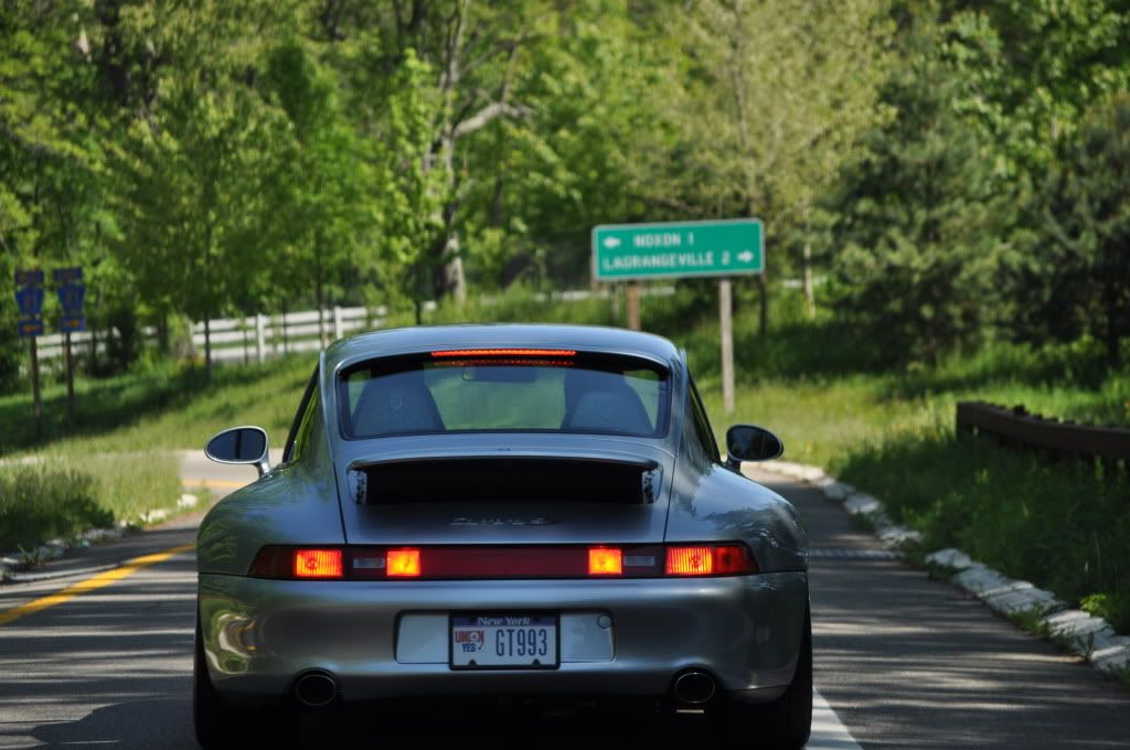
Photo courtesy of Toddster's wife.
The hardest part for me was sourcing out the sockets. After some trial and error I ended up buying a reverse light harness from a rennlister here. The sockets need to be very shallow in the back because unlike on a 964 (did that mod on my RSA as well) there is practically no room once the 993 reflector is reinstalled.
Here's the end result:
Photo courtesy of Toddster's wife.