Protomotive Stage 1 Twin Turbo Install DIY
 01-22-2009, 04:31 PM
#1
Rennlist Member
Thread Starter
A lot of people have been asking for more detail about my Protomotive Stage 1 TT upgrade, so this write-up gives some info and pics. Hopefully this will (a) help anyone considering forced induction to decide, and (b) help the install go easier for those who choose a Protomotive kit.
Caveat: I make NO claims about the safety or quality of the methods or equipment described herein; I’m just describing my experience. Don’t attempt this if you are not qualified because you could really hurt your car and/or yourself!
Contents:
1. Why do it?
2. Limitations / applications
3. The kit and preparation
4. Removal of stuff
5. Installation – engine bay
6. Installation – underneath
7. Startup
8. Tuning & other issues
9. Possible improvements
1. Why Do It?
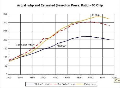
After a thread last year about choosing Protomotive vs. TPC supercharger vs. factory 993TT engine, I decided on the Protomotive kit. Reasons were (a) reasonable cost, (b) I could install myself, which would be a rewarding project, (c) future upgradability (low compression pistons = lots more hp), and (d) simple and reliable for track use. The project took 5 months from placing the order until street-ready, but with this info it could possibly be done in 4 months (no less). Results: +115 rwhp (135 hp flywheel). Adds 47 lbs over stock.
Power gains can be approximated by multiplying the baseline power by the Pressure Ratio (e.g. for 5 psi, PR=1+(5/14.5)=1.34). This is shown in the following graphs, along with my actual dyno results (Dyno Dynamics). By the way, I see 5 psi boost at 3900 rpm, increasing to 6 psi at redline.

2. Limitations / Applications.
My car is a 1995 so I don’t have the OBD2 issues and I’m not subject to emissions testing. Thus, I have a cat-free and SAI-free system (and no CEL!). Apparently Protomotive has supplied kits for OBD2 that retain the factory cats and SAI system. Protomotive kits do not lose the heater blower or cruise control functionality, a plus. No special tools or electrical jury-rigging are required.
3. The Kit and Preparation.
First off, the kit assembled to a bench engine is shown here.

and here:
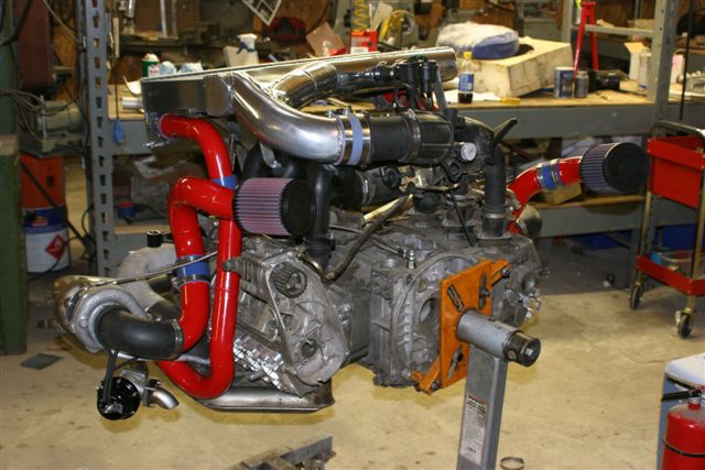
As delivered, it included:
a) Modified heat exchangers with turbos (Garrett T3 Super 60) and Tial wastegates bolted up,
b) Center-mount muffler (bolts to the turbo exhaust),
c) Air piping (red),
d) Intercooler with blow-off valves attached,
e) Misc parts: chip, adjustable fuel pressure regulator, aluminum valve covers, and hardware.
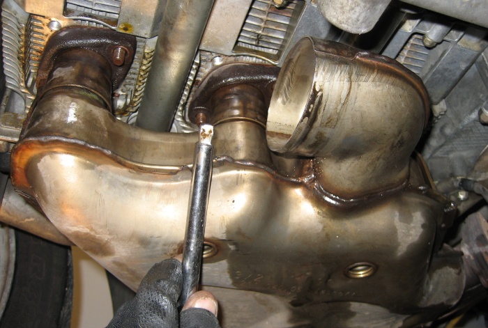
The only think lacking was instructions, and they were sorely missed. Otherwise, www.mcmaster.com and www.boltdepot.com are good sources of parts. When ordering the kit, identify the number and exact location of your needed O2 sensor ports. Since a 1995 only uses 1 sensor, plus my new wideband sensor, I needed 2 ports on the passenger side. Follow the mfrs guidelines on installation: O2 sensors should not point up or they’ll collect water and fail. (You’ll see I have a useless O2 sensor bung on the driver’s side, and located at 6 o’clock. Oops.)
Prep for the install should include:
a) Compression & leakdown test (probably wise).
b) Set of spark plugs. I used stock FR5 DTC plugs, which may have a relatively short life here. Do not try Denso Iridium IK20, which do not work in this application, probably due to the large gap. They caused total misfiring at high rpm.
c) Install an AFR gauge, such as the Innovate Motorsports LC-1. This is a must.
d) Buy new nuts for re-installing the heat exchangers, and some good copper-based (high temp) anti seize compound like copa-slip.
e) Buy or borrow a Bosch Hammer, OBD scanner, Durametric, Scantool, or whatever.
f ) Install a rear wing that will fit the intercooler. Stock decklid won’t work, so you need a spoiler & decklid for Turbo, Turbo S, or GT2. Here’s an important tip: when you bolt up the new decklid, it won’t be perfectly centered. To adjust: remove the decklid, grab the steel arm that the lid mounts to, and push/pull to bend it slightly. Repeat for the 2nd arm. Remount the decklid, check for fit, and repeat as needed.
g) Probably larger fuel injectors. The stock fuel injectors can only handle around 5.5 bar (engine at idle, vacuum line to FPR disconnected) and I can confirm they lock up around 6+ bar. So they’re good for around 400 hp apparently, but this seems to be the ragged edge. I was running a bit lean, so I switched to larger injectors, specifically Ford Racing injectors; M-9593-F302, 42 lb/hr (441 cc/min), approx. $450 for 8.
h) Baseline dyno pull (optional).
i) If you’re considering buying a lift, now is the time. You’ll be really glad you did.
j) Buy or borrow a fuel pressure gauge, and buy an extra brass fuel port cap from Porsche (993.110.218.0). Also mandatory.
4. Removal of Stuff.
Intro notes:
- I don’t discuss every little nut & bolt that you need to remove if they are pretty obvious.
- Be organized! Always put nuts & bolts in labeled zip-loc baggies.
a) Remove the rear wheels, the wheel liners, corner lights, and remove the rear bumper cover. Don’t loosen or remove the center reflector, though, because it’s very hard to re-install. Undo its electrical connector in the black box in the engine compartment on the right side.
b) Remove the metal support arms for the bumper cover (2 per side); not necessary but worth the few minutes.
c) Remove mufflers, catalytic converter, and heat exchangers (if you have the OBD2 kit, the cat and heat exchangers stay). Spray the heat exchanger nuts with penetrating fluid (like PB Blaster) a day in advance. The barrel nuts in the heat exchangers can strip. I stripped one, leaving me to dremel and chisel until I finally got it loose. It wasn’t pretty. I used a short allen-wrench socket on a wobble extension. A long allen wrench socket may also work.
d) Remove the tins that separate the engine bay from underneath. These are not re-used. You are also removing the clutch vent hose, so you’ll need to plug it at the tranny or install a breather there.
e) In the engine bay, remove the heater blower assembly. (two 10mm bolts)
f) Remove the airbox. You won’t need it anymore.
g) Remove either the left & right intake runners or else the entire intake manifold. I left the center section in place since I didn’t want to deal with any of the connectors but I don’t know if this saved any time. Cover the air intakes with duct tape so you don’t drop anything in.
h) Remove the MAF body and the rubber intake “L” between the MAF and throttle body.
i) Clean out the oil that has collected in your intake manifold. This occurs because the manifold is piped to your oil sump and the manifold vacuum pulls oil vapor into the intake. Later on, you’ll cut that connection and vent the oil tank to atmosphere, or else it would pressurize the oil tank under boost (which would cause oil to back up in your turbos since they are gravity drained).
j) Check/tighten all your connections in your intake manifold. I found that my entire throttle body was being held on by just one of the four screws. Yikes.
k) While you’re in there items: remove the ISV and clean it out with carb cleaner. Remove the MAF sensor and spray it down with CRC Mass Air Flow Sensor Cleaner. Clean up your filthy engine bay. Replace the fuel filter if it is due.
l) Remove the SAI pump because it is covering up your oil source (the main oil galley).
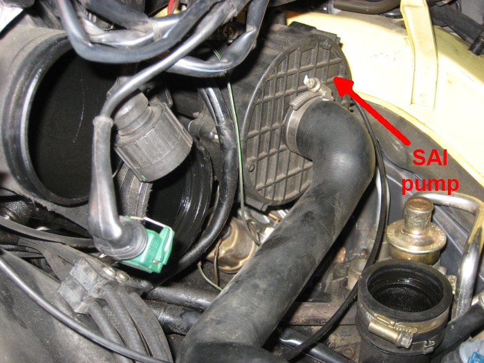
Remove the 4 bolts that hold down the pump bracket and remove the air pump and its hoses. If you’re scrapping the SAI pump, you MUST reinstall the 4 bolts since they bolt the cover to galley. I believe you’ll need to buy shorter bolts. If you are reinstalling the SAI pump, I believe you’ll need to cut up the bracket a bit since it will interfere with your new oil fittings that screw onto your engine. I left my SAI check valve in place, although I believe that it (and its base) can be removed and replaced by a plug (plug kit is available from Patrick Motorsports http://www.patrickmotorsports.com/part/610/. I simply capped the check valve for now.
m) Install the oil line fittings and run the lines to where the turbos will be. Clean the area well before removing the hex plug, and do NOT drop anything in the oil galley.

Keep the oil lines from rubbing against anything.
n) Remove the fuel pressure regulator. Put down some rags because you’ll spill a lot of gas. Remove the retaining clip then pull out the FPR. This can be hard to remove, but be careful about prying it out since you can bend the retaining frame.

5. Installation – Engine Bay.
a) If you are installing new injectors: unbolt the 2 fuel rails, detach each electrical connector, pull up the fuel rail with the injectors attached, remove the clip holding each injector, and remove each injector from its fuel rail. You’ll spill a lot of fuel here so have towels underneath at all times. When installing new injectors, I preferred to clip each injector into the fuel rail first so that I could ensure they were fully affixed, and then push the entire assembly into place on the intake. Then attach electrical connectors and bolt the fuel rails down.
b) Install the new adjustable FPR. Important: put a little grease (lithium?) on the o-rings or else insertion will be difficult and you could damage the o-rings. Reinstall the retaining clip. Bolt the fuel rail back in place if you had it pulled loose.
c) Install oil tank breather (provided). A fat rubber hose runs from the rubber intake L to the oil tank, over on the right side of the engine bay. Some cars may have a visible connection there, but mine did not so I cut the line. At the rubber intake L, install the metal plug (provided). This procedure will prevent the oil tank from getting pressurized under boost and keep it vented to atmospheric pressure. Secure with zip ties.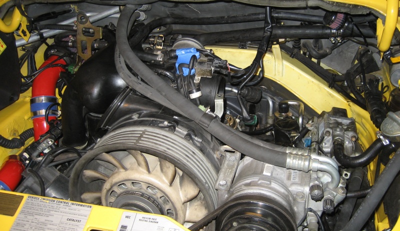
d) Behind that hose is a smaller hose that runs from the intake (just aft of the ISV connection) to the right side of the engine bay. Cut this hose near the tank breather and install t-fitting (provided). This t-fitting is blocked on one side, and provides a connection for a boost gauge (if requested) as well as a vacuum connection for the blow-off valves.
e) Reassemble the intake system, including the MAF, and tighten all connections.
f) Pressure test the intake system (alternatively, do it later to the assembled system). I believe that Home Depot has the needed parts to attach to the MAF: a short rubber boot with an end cap and band clamp. Drill the end cap for a compressed air fitting. You need a compressed air tank; nothing else will work. Pressurize to about 10 psi with compressed air then see how long it takes to bleed off. It seems normal for some air to leak from the resonance flap shaft. I’m not sure how long it should take to drop to zero pressure, but maybe 15 sec is a good start. Diagnosing leaks is best done with a smoke machine or smoke sticks… blowing in cigar smoke doesn’t work so well, believe it or not.
g) If desired, install a boost gauge. To mount, I used a 2-1/16” a-pillar gauge pod for a 1986-89 RX-7 (from Jegs) and adjusted to fit with a heat gun. I ran the vacuum tubing through the firewall, behind the rear deck, under the rear vinyl panels, under the inner door sill, and up the a-pillar. Running it under the center tunnel might work, but I didn’t investigate that.
6. Installation – Underneath.
a) Remove both lower valve covers.
b) Replace spark plugs.
c) Install aluminum valve covers (provided). Using new screws is wise since they are allen-head screws that strip easily. Installing new gaskets is probably also wise, since replacing them will not be a simple chore anymore.
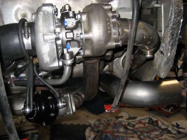
d) Bolt up the headers with turbos and wastegates attached. On the headers, use copper-based antiseize.
e) Bolt up the muffler. If it doesn’t mate well to the turbos, loosen up the connection between the turbo and header and tweak. My kit came with a Dynomax 2-in / 2-out aluminized-steel muffler that suffered an internal failure after a short time. I replaced it with a Magnaflow 5”x8” muffler (#12468) that seems to be lighter, is magnetic stainless steel, and is visibly better quality. This also gave me a chance to have some proper tips installed.
f) Install oil drain pipes to the valve covers but do not attach to the turbos yet. A steel hose clamp is not recommended due to potential damage to the silicone.
g) Do not attach oil supply lines to turbos yet.
h) Tighten all connections.
i) Back in the engine bay, install the turbo intake piping, turbo outlet piping, and intercooler. Pretty straightforward.

Intercooler:

Right side:

j) Pressure test the system. Easy to do at this point; at Home Depot, buy 2 rubber end caps, 2” diameter. Replace one air filter with an end cap and tighten down. Drill a hole in the other end cap, install a compressed air fitting, and install the cap on the other air intake pipe in place of the air filter.

k) Remove factory chip and install new chip (provided). DIY for this step can be found at p-car.com or pcarworkshop.com.
7. Startup
a) Check fuel pressure at the test port with a fuel pressure gauge. Especially if you’re running stock injectors, you absolutely cannot skip this step. Too much pressure and your injectors will seize; too little and you’ll run lean. I believe Protomotive specifies 5.5 bar, engine idling, vacuum line disconnected. Note – if you need to get fuel pressure with the engine OFF, pull the DME relay from the fuse box in the front trunk. It’s clearly labeled DME. Buy a fuse holder from Radio Shack and crimp two spade connectors to it. Jump pin 30 to pin 87b (where the DME was) to force the fuel pump on. Measure fuel pressure and adjust as needed. Install brass cap at 1.8 + 0.4 ft-lb. Reinstall DME.
b) Pre-lubricate the turbos. I pushed oil into the turbos using a brake bleeder catch bottle (squeezing it to push the oil). Maybe not needed, but I was being cautious.
c) Attach oil supply lines to the turbos.
d) Pull the DME relay again. By pulling this relay, the fuel pump will not provide fuel, so the engine will not start. That allows you to crank the engine and fill the oil lines and turbo with oil so the turbos are not run dry even momentarily. Put towels under your turbo drains.
e) Turn the engine over until oil comes out the turbo drain. Congrats, your turbos have oil. Attach oil drains to the turbo and replace the DME.
f) Reinstall heater blower, bumper cover, and anything else you removed.
g) Start the car but don’t touch the accelerator for 2 minutes. This is done after any chip change. Check for oil leaks anywhere.
h) Go for a drive, you’ve earned it! Make it short, though. Read on.
8. Tuning & Other issues
a) Some recommend driving 300 miles before getting into boost, others ignore this. I offer no opinion.
b) Once you are past the “break in” period (0 or 300 miles or whatever), find a stretch of road where you can conveniently, safely, and legally accelerate at full throttle (like a race track). If you can record power output with a data logger then start the full-throttle runs at a set spot since you’ll want to use this location again in the future.
c) Hit the boost! It sounds like a typical sport exhaust (not loud at all) until the wastegates open up. Since the wastegates dump to atmosphere, it’s loud when on boost (but not inside the car). The loud woooosh of the turbos spinning up, and the PISHHHHH of the blow off valves will put a huge smile on your face.
d) Check your AFRs at wide-open throttle (WOT). Go back and adjust fuel pressure if your AFRs are off. Opinions vary, but keeping AFRs in the range 11.5 to 12.0 throughout the rev range works well on turbos. I saw my AFRs drift over 13.5 at redline with stock injectors. Perhaps I could have tweaked the fuel pressure up a bit (but remember, around 6 bar and the injectors won’t work) but instead I installed larger injectors, described above.
e) If you have a Durametric, you can log timing. If you are OBD2, you can watch timing real-time with a Scangauge 2. Ask your tuner what timing should be, and watch if the ECU is holding timing or retarding it.
f) Protomotive’s kit normally comes with very conservative 91-octane tuning. My car eventually ended up with more aggressive 93-octane timing, tweaked fueling to even out the AFR curve, and with idle bumped up to 950 rpm to try to help with LWFW stalling. Protomotive will custom write chips at a very reasonable cost.
g) Ideally, we want to know if our engine is knocking. I currently know of no way to do so. OBD2 cars can watch timing with the Scangauge 2 to determine if timing is being pulled. OBD1 owners can attempt to count knock events with a Curtis counter ($15) but my results are so far inconclusive with that unit.
h) Regularly check all your nuts & bolts (every 500 miles), because things DO loosen up. I’ve found a couple loosening nuts, and I had a wastegate come loose. Eventually you can relax your regimen a bit.
9. Possible Improvements
a) Protecting and securing the oil lines may be wise. High-temp spiral wrap might be used for protection (PTFE spiral wrap sleeving is good to 500F, available from www.mcmaster.com). Experiment at your own risk. Edit: I installed this wrap and it's holding up fine.
b) The sheet metal separating the engine bay from below is not used, due the piping passing through the area. This does not worry me greatly, though. Edit: I've since installed the engine tins (modified for the piping) to prevent the engine from re-ingesting hot air.
c) The spark plug wires are not secured from movement. Finding a way to secure them may be prudent. Edit: re-installing the modified engine tins solved this.
If this DIY was helpful to you, then please contribute yourself and help advance our body of knowledge! If I have forgotten something or you see an error, please let me know and I’ll correct it.
Caveat: I make NO claims about the safety or quality of the methods or equipment described herein; I’m just describing my experience. Don’t attempt this if you are not qualified because you could really hurt your car and/or yourself!
Contents:
1. Why do it?
2. Limitations / applications
3. The kit and preparation
4. Removal of stuff
5. Installation – engine bay
6. Installation – underneath
7. Startup
8. Tuning & other issues
9. Possible improvements
1. Why Do It?
After a thread last year about choosing Protomotive vs. TPC supercharger vs. factory 993TT engine, I decided on the Protomotive kit. Reasons were (a) reasonable cost, (b) I could install myself, which would be a rewarding project, (c) future upgradability (low compression pistons = lots more hp), and (d) simple and reliable for track use. The project took 5 months from placing the order until street-ready, but with this info it could possibly be done in 4 months (no less). Results: +115 rwhp (135 hp flywheel). Adds 47 lbs over stock.
Power gains can be approximated by multiplying the baseline power by the Pressure Ratio (e.g. for 5 psi, PR=1+(5/14.5)=1.34). This is shown in the following graphs, along with my actual dyno results (Dyno Dynamics). By the way, I see 5 psi boost at 3900 rpm, increasing to 6 psi at redline.
2. Limitations / Applications.
My car is a 1995 so I don’t have the OBD2 issues and I’m not subject to emissions testing. Thus, I have a cat-free and SAI-free system (and no CEL!). Apparently Protomotive has supplied kits for OBD2 that retain the factory cats and SAI system. Protomotive kits do not lose the heater blower or cruise control functionality, a plus. No special tools or electrical jury-rigging are required.
3. The Kit and Preparation.
First off, the kit assembled to a bench engine is shown here.
and here:
As delivered, it included:
a) Modified heat exchangers with turbos (Garrett T3 Super 60) and Tial wastegates bolted up,
b) Center-mount muffler (bolts to the turbo exhaust),
c) Air piping (red),
d) Intercooler with blow-off valves attached,
e) Misc parts: chip, adjustable fuel pressure regulator, aluminum valve covers, and hardware.
The only think lacking was instructions, and they were sorely missed. Otherwise, www.mcmaster.com and www.boltdepot.com are good sources of parts. When ordering the kit, identify the number and exact location of your needed O2 sensor ports. Since a 1995 only uses 1 sensor, plus my new wideband sensor, I needed 2 ports on the passenger side. Follow the mfrs guidelines on installation: O2 sensors should not point up or they’ll collect water and fail. (You’ll see I have a useless O2 sensor bung on the driver’s side, and located at 6 o’clock. Oops.)
Prep for the install should include:
a) Compression & leakdown test (probably wise).
b) Set of spark plugs. I used stock FR5 DTC plugs, which may have a relatively short life here. Do not try Denso Iridium IK20, which do not work in this application, probably due to the large gap. They caused total misfiring at high rpm.
c) Install an AFR gauge, such as the Innovate Motorsports LC-1. This is a must.
d) Buy new nuts for re-installing the heat exchangers, and some good copper-based (high temp) anti seize compound like copa-slip.
e) Buy or borrow a Bosch Hammer, OBD scanner, Durametric, Scantool, or whatever.
f ) Install a rear wing that will fit the intercooler. Stock decklid won’t work, so you need a spoiler & decklid for Turbo, Turbo S, or GT2. Here’s an important tip: when you bolt up the new decklid, it won’t be perfectly centered. To adjust: remove the decklid, grab the steel arm that the lid mounts to, and push/pull to bend it slightly. Repeat for the 2nd arm. Remount the decklid, check for fit, and repeat as needed.
g) Probably larger fuel injectors. The stock fuel injectors can only handle around 5.5 bar (engine at idle, vacuum line to FPR disconnected) and I can confirm they lock up around 6+ bar. So they’re good for around 400 hp apparently, but this seems to be the ragged edge. I was running a bit lean, so I switched to larger injectors, specifically Ford Racing injectors; M-9593-F302, 42 lb/hr (441 cc/min), approx. $450 for 8.
h) Baseline dyno pull (optional).
i) If you’re considering buying a lift, now is the time. You’ll be really glad you did.
j) Buy or borrow a fuel pressure gauge, and buy an extra brass fuel port cap from Porsche (993.110.218.0). Also mandatory.
4. Removal of Stuff.
Intro notes:
- I don’t discuss every little nut & bolt that you need to remove if they are pretty obvious.
- Be organized! Always put nuts & bolts in labeled zip-loc baggies.
a) Remove the rear wheels, the wheel liners, corner lights, and remove the rear bumper cover. Don’t loosen or remove the center reflector, though, because it’s very hard to re-install. Undo its electrical connector in the black box in the engine compartment on the right side.
b) Remove the metal support arms for the bumper cover (2 per side); not necessary but worth the few minutes.
c) Remove mufflers, catalytic converter, and heat exchangers (if you have the OBD2 kit, the cat and heat exchangers stay). Spray the heat exchanger nuts with penetrating fluid (like PB Blaster) a day in advance. The barrel nuts in the heat exchangers can strip. I stripped one, leaving me to dremel and chisel until I finally got it loose. It wasn’t pretty. I used a short allen-wrench socket on a wobble extension. A long allen wrench socket may also work.
d) Remove the tins that separate the engine bay from underneath. These are not re-used. You are also removing the clutch vent hose, so you’ll need to plug it at the tranny or install a breather there.
e) In the engine bay, remove the heater blower assembly. (two 10mm bolts)
f) Remove the airbox. You won’t need it anymore.
g) Remove either the left & right intake runners or else the entire intake manifold. I left the center section in place since I didn’t want to deal with any of the connectors but I don’t know if this saved any time. Cover the air intakes with duct tape so you don’t drop anything in.
h) Remove the MAF body and the rubber intake “L” between the MAF and throttle body.
i) Clean out the oil that has collected in your intake manifold. This occurs because the manifold is piped to your oil sump and the manifold vacuum pulls oil vapor into the intake. Later on, you’ll cut that connection and vent the oil tank to atmosphere, or else it would pressurize the oil tank under boost (which would cause oil to back up in your turbos since they are gravity drained).
j) Check/tighten all your connections in your intake manifold. I found that my entire throttle body was being held on by just one of the four screws. Yikes.
k) While you’re in there items: remove the ISV and clean it out with carb cleaner. Remove the MAF sensor and spray it down with CRC Mass Air Flow Sensor Cleaner. Clean up your filthy engine bay. Replace the fuel filter if it is due.
l) Remove the SAI pump because it is covering up your oil source (the main oil galley).
Remove the 4 bolts that hold down the pump bracket and remove the air pump and its hoses. If you’re scrapping the SAI pump, you MUST reinstall the 4 bolts since they bolt the cover to galley. I believe you’ll need to buy shorter bolts. If you are reinstalling the SAI pump, I believe you’ll need to cut up the bracket a bit since it will interfere with your new oil fittings that screw onto your engine. I left my SAI check valve in place, although I believe that it (and its base) can be removed and replaced by a plug (plug kit is available from Patrick Motorsports http://www.patrickmotorsports.com/part/610/. I simply capped the check valve for now.
m) Install the oil line fittings and run the lines to where the turbos will be. Clean the area well before removing the hex plug, and do NOT drop anything in the oil galley.
Keep the oil lines from rubbing against anything.
n) Remove the fuel pressure regulator. Put down some rags because you’ll spill a lot of gas. Remove the retaining clip then pull out the FPR. This can be hard to remove, but be careful about prying it out since you can bend the retaining frame.
5. Installation – Engine Bay.
a) If you are installing new injectors: unbolt the 2 fuel rails, detach each electrical connector, pull up the fuel rail with the injectors attached, remove the clip holding each injector, and remove each injector from its fuel rail. You’ll spill a lot of fuel here so have towels underneath at all times. When installing new injectors, I preferred to clip each injector into the fuel rail first so that I could ensure they were fully affixed, and then push the entire assembly into place on the intake. Then attach electrical connectors and bolt the fuel rails down.
b) Install the new adjustable FPR. Important: put a little grease (lithium?) on the o-rings or else insertion will be difficult and you could damage the o-rings. Reinstall the retaining clip. Bolt the fuel rail back in place if you had it pulled loose.
c) Install oil tank breather (provided). A fat rubber hose runs from the rubber intake L to the oil tank, over on the right side of the engine bay. Some cars may have a visible connection there, but mine did not so I cut the line. At the rubber intake L, install the metal plug (provided). This procedure will prevent the oil tank from getting pressurized under boost and keep it vented to atmospheric pressure. Secure with zip ties.
d) Behind that hose is a smaller hose that runs from the intake (just aft of the ISV connection) to the right side of the engine bay. Cut this hose near the tank breather and install t-fitting (provided). This t-fitting is blocked on one side, and provides a connection for a boost gauge (if requested) as well as a vacuum connection for the blow-off valves.
e) Reassemble the intake system, including the MAF, and tighten all connections.
f) Pressure test the intake system (alternatively, do it later to the assembled system). I believe that Home Depot has the needed parts to attach to the MAF: a short rubber boot with an end cap and band clamp. Drill the end cap for a compressed air fitting. You need a compressed air tank; nothing else will work. Pressurize to about 10 psi with compressed air then see how long it takes to bleed off. It seems normal for some air to leak from the resonance flap shaft. I’m not sure how long it should take to drop to zero pressure, but maybe 15 sec is a good start. Diagnosing leaks is best done with a smoke machine or smoke sticks… blowing in cigar smoke doesn’t work so well, believe it or not.
g) If desired, install a boost gauge. To mount, I used a 2-1/16” a-pillar gauge pod for a 1986-89 RX-7 (from Jegs) and adjusted to fit with a heat gun. I ran the vacuum tubing through the firewall, behind the rear deck, under the rear vinyl panels, under the inner door sill, and up the a-pillar. Running it under the center tunnel might work, but I didn’t investigate that.
6. Installation – Underneath.
a) Remove both lower valve covers.
b) Replace spark plugs.
c) Install aluminum valve covers (provided). Using new screws is wise since they are allen-head screws that strip easily. Installing new gaskets is probably also wise, since replacing them will not be a simple chore anymore.
d) Bolt up the headers with turbos and wastegates attached. On the headers, use copper-based antiseize.
e) Bolt up the muffler. If it doesn’t mate well to the turbos, loosen up the connection between the turbo and header and tweak. My kit came with a Dynomax 2-in / 2-out aluminized-steel muffler that suffered an internal failure after a short time. I replaced it with a Magnaflow 5”x8” muffler (#12468) that seems to be lighter, is magnetic stainless steel, and is visibly better quality. This also gave me a chance to have some proper tips installed.
f) Install oil drain pipes to the valve covers but do not attach to the turbos yet. A steel hose clamp is not recommended due to potential damage to the silicone.
g) Do not attach oil supply lines to turbos yet.
h) Tighten all connections.
i) Back in the engine bay, install the turbo intake piping, turbo outlet piping, and intercooler. Pretty straightforward.
Intercooler:
Right side:
j) Pressure test the system. Easy to do at this point; at Home Depot, buy 2 rubber end caps, 2” diameter. Replace one air filter with an end cap and tighten down. Drill a hole in the other end cap, install a compressed air fitting, and install the cap on the other air intake pipe in place of the air filter.
k) Remove factory chip and install new chip (provided). DIY for this step can be found at p-car.com or pcarworkshop.com.
7. Startup
a) Check fuel pressure at the test port with a fuel pressure gauge. Especially if you’re running stock injectors, you absolutely cannot skip this step. Too much pressure and your injectors will seize; too little and you’ll run lean. I believe Protomotive specifies 5.5 bar, engine idling, vacuum line disconnected. Note – if you need to get fuel pressure with the engine OFF, pull the DME relay from the fuse box in the front trunk. It’s clearly labeled DME. Buy a fuse holder from Radio Shack and crimp two spade connectors to it. Jump pin 30 to pin 87b (where the DME was) to force the fuel pump on. Measure fuel pressure and adjust as needed. Install brass cap at 1.8 + 0.4 ft-lb. Reinstall DME.
b) Pre-lubricate the turbos. I pushed oil into the turbos using a brake bleeder catch bottle (squeezing it to push the oil). Maybe not needed, but I was being cautious.
c) Attach oil supply lines to the turbos.
d) Pull the DME relay again. By pulling this relay, the fuel pump will not provide fuel, so the engine will not start. That allows you to crank the engine and fill the oil lines and turbo with oil so the turbos are not run dry even momentarily. Put towels under your turbo drains.
e) Turn the engine over until oil comes out the turbo drain. Congrats, your turbos have oil. Attach oil drains to the turbo and replace the DME.
f) Reinstall heater blower, bumper cover, and anything else you removed.
g) Start the car but don’t touch the accelerator for 2 minutes. This is done after any chip change. Check for oil leaks anywhere.
h) Go for a drive, you’ve earned it! Make it short, though. Read on.
8. Tuning & Other issues
a) Some recommend driving 300 miles before getting into boost, others ignore this. I offer no opinion.
b) Once you are past the “break in” period (0 or 300 miles or whatever), find a stretch of road where you can conveniently, safely, and legally accelerate at full throttle (like a race track). If you can record power output with a data logger then start the full-throttle runs at a set spot since you’ll want to use this location again in the future.
c) Hit the boost! It sounds like a typical sport exhaust (not loud at all) until the wastegates open up. Since the wastegates dump to atmosphere, it’s loud when on boost (but not inside the car). The loud woooosh of the turbos spinning up, and the PISHHHHH of the blow off valves will put a huge smile on your face.
d) Check your AFRs at wide-open throttle (WOT). Go back and adjust fuel pressure if your AFRs are off. Opinions vary, but keeping AFRs in the range 11.5 to 12.0 throughout the rev range works well on turbos. I saw my AFRs drift over 13.5 at redline with stock injectors. Perhaps I could have tweaked the fuel pressure up a bit (but remember, around 6 bar and the injectors won’t work) but instead I installed larger injectors, described above.
e) If you have a Durametric, you can log timing. If you are OBD2, you can watch timing real-time with a Scangauge 2. Ask your tuner what timing should be, and watch if the ECU is holding timing or retarding it.
f) Protomotive’s kit normally comes with very conservative 91-octane tuning. My car eventually ended up with more aggressive 93-octane timing, tweaked fueling to even out the AFR curve, and with idle bumped up to 950 rpm to try to help with LWFW stalling. Protomotive will custom write chips at a very reasonable cost.
g) Ideally, we want to know if our engine is knocking. I currently know of no way to do so. OBD2 cars can watch timing with the Scangauge 2 to determine if timing is being pulled. OBD1 owners can attempt to count knock events with a Curtis counter ($15) but my results are so far inconclusive with that unit.
h) Regularly check all your nuts & bolts (every 500 miles), because things DO loosen up. I’ve found a couple loosening nuts, and I had a wastegate come loose. Eventually you can relax your regimen a bit.
9. Possible Improvements
a) Protecting and securing the oil lines may be wise. High-temp spiral wrap might be used for protection (PTFE spiral wrap sleeving is good to 500F, available from www.mcmaster.com). Experiment at your own risk. Edit: I installed this wrap and it's holding up fine.
b) The sheet metal separating the engine bay from below is not used, due the piping passing through the area. This does not worry me greatly, though. Edit: I've since installed the engine tins (modified for the piping) to prevent the engine from re-ingesting hot air.
c) The spark plug wires are not secured from movement. Finding a way to secure them may be prudent. Edit: re-installing the modified engine tins solved this.
If this DIY was helpful to you, then please contribute yourself and help advance our body of knowledge! If I have forgotten something or you see an error, please let me know and I’ll correct it.
Last edited by TheOtherEric; 11-17-2010 at 09:10 PM. Reason: temporarily edited

 ..... enjoyed each & every detail.

Trending Topics
01-22-2009, 07:52 PM
#8
Guru
Lifetime Rennlist
Member
Rennlist Small
Business Sponsor
Lifetime Rennlist
Member
Rennlist Small
Business Sponsor
Awesome write-up Eric, great work!
It always seems to be the case that the after install tuning and testing is more laborious than the install itself. Ask me how I know
It always seems to be the case that the after install tuning and testing is more laborious than the install itself. Ask me how I know
 01-23-2009, 12:14 AM
#12
Rennlist Member
Thread Starter

Originally Posted by MarkD
...Are you going to write a review? I'm curious of performance. I might have missed it...
Why "no less" than 4 months to install?
Why "no less" than 4 months to install?
Driving Impressions. The car drives, well, exactly the same as before, it just pulls a lot harder! And makes a lot of cool noises. Since it's still high compression, you don't get turbo lag. From 3500 rpm up, you get a nice bit of extra power. It's not some dramatic burst of force; it's actually very managable, even on the track. I've only tracked it a couple times with turbos, but I didn't change my driving style at all (except brake earlier!). On the street, it's a lot easier to get the tail loose.
Protomotive could have supplied turbos that spool up faster, moving the torque curve over ~500 rpm. That would be nice on the street, but would sacrifice some top end power and upgradability (these turbos are good for 500hp).Scorecard.
Performance = A- (points deducted for little low-end torque gain)
Ease of Install = C (lack of instructions)
Robustness = tbd
Fit & Finish = A
Component Quality = B (muffler)
Completeness of Kit = B+ (securing of spark plug wires & oil lines)
I say "no less than 4 months" because it takes 2.5 months just to deliver (I doubt any quicker) then several weeks to install, wait for misc. parts deliveries, install more, test, retune, retest, etc. That's just the way these projects go if you have a job or family.
Last edited by TheOtherEric; 01-23-2009 at 11:12 AM.
01-23-2009, 11:26 AM
#15
Rennlist Member
Thread Starter
It was $14,000 shipped. That doesn't include rear wing, injectors, dyno pulls, spark plugs, etc. BTW, here's the new muffler arrangement, with nice tips. Amazing work by Chicago Performance & Tuning, www.gocpt.com.

