When you click on links to various merchants on this site and make a purchase, this can result in this site earning a commission. Affiliate programs and affiliations include, but are not limited to, the eBay Partner Network.
Wow, nice to see those pics.
I attached the PET Diagrams for your reference.
I believe Part #12 is the one that directs the line thru the heat shield to get to the new valve location on the back side of the exhaust.
Ok, the next thing I'm trying to figure out is the sequence of parts from the COV all the way to the valves (Later, I'll figure out exactly where to route the line).
So it looks like from the COV runs a length of vacuum tube (cut from 900-918-005-40). The last few inches of this length of vacuum tube gets threaded through one of the 991-111-492-00 steel lines. The tube and steel line then plug into one end of the holder (991-111-488-00). The other end of the holder gets plugged into the remaining length of vacuum tube (900-918-005-40) that is threaded through the other steel line (991-111-492-00). Lastly, this tube/steel line gets plugged into the right exhaust valve. And 991-111-491-00 is used to connect the two valves.
(NOTE: Saying a lot of this from memory and going back to notes along the way, and I got a couple of things "wrong". Sorry. There are two lengths of steel flexi-line, and while one length does connect to the Tekalan, the other length (80mm) does not and is the lenth that simply connects the two exhaust flappers...)
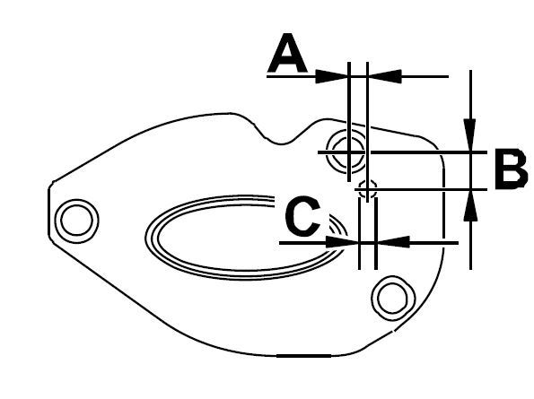
If you haven't already, get the carrier heat shield ready. You have to create a hole. Following diagram shows the positioning of said hole.
A = 11.5 mm
B = 21.4 mm
C = Diameter (the hole you create) 7 mm + 0.2
Get the hole ready.... Cut a length (420 mm) off the Tekalan tubing. Then take the supplied 190 mm steel flexi-line (991.111.492.00) and fit to the piece of Tekalan that you cut to 420 mm (inserting about 10 mm).
Attach the supplied holder (991.111.488.00) to the carrier heat shield (in the hole you created). Slide the flexi-line onto the COV-side of the holder. Lock in place with the clips provided.
If you haven't already, pull the black "L" shaped connector off the existing vacuum line that connects to the COV-side, and put it on the end of the new Tekalan tubing that you've just connected to the heat shield. Install the heat shield, then connect the tubing/black connector to the COV valve.
On the new PSE, take the 80mm length of flexi-line and connect the two flaps, and use clamps to lock in place.
You now have to get the new PSE in place.... Once you have it up and in, you can connect the flexi-line to the holder on the heat shield of the engine carrier. I think you will also clamp this in place, but align everything before you do in case you need to move it some.
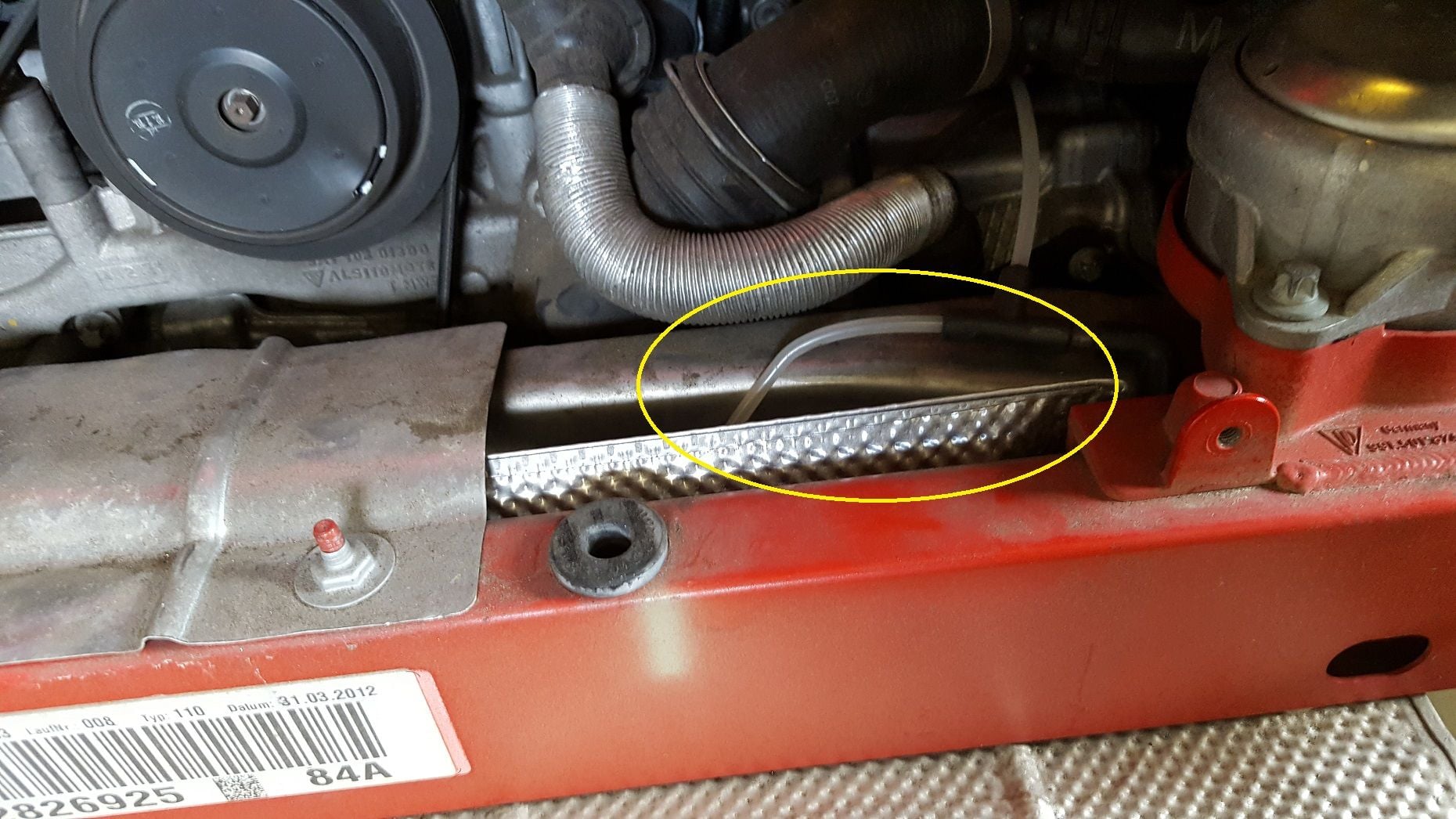
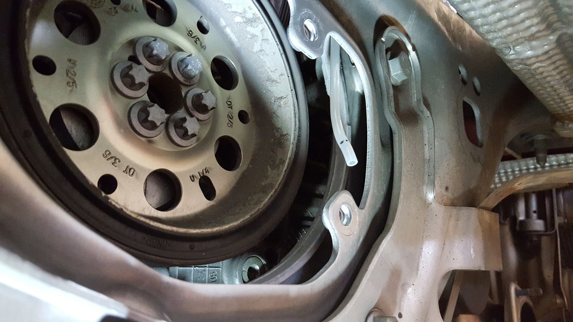
It turns out that the heat shield you're referring to already has that hole. See 2nd pic in this post.
Here's how I plan to run the new vacuum tube.
And here's where the tube will end up (right by where the holder plugs into the hole in the heat shield. Does the holder just "plug" or "snap" into the hole? It doesn't look like it could thread or screw into the hole.
Wow, that's great that the hole already exists... Not sure what the determining factor might be for having / not-having -- but consider it a gift and you don't have to worry about drilling. Now, you may still want to remove from the engine carrier to aid in installing the holder, etc. But you may find it not necessary.
I don't have one of the holders to look-at but from memory it is simply inserted and fits snug in place. Not threaded or anything.
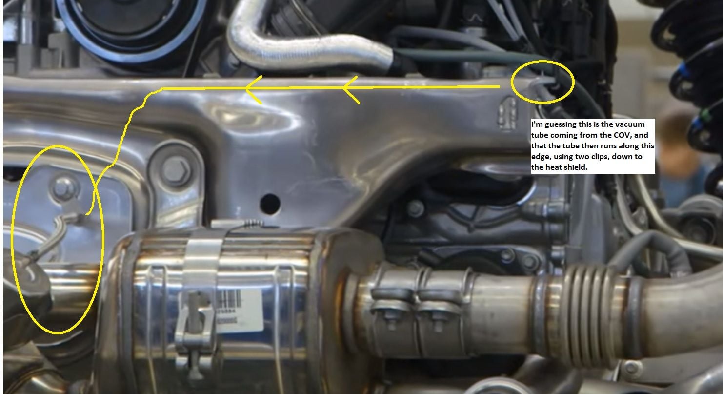
I found this picture on another forum (I added the red annotation). As I wrote in that annotation, I believe that one of the ends of the holder (#12) gets pushed thru the open hole. Then the top bolt in the heat shield gets removed, the holder's bracket hole gets lined up with the hole from which the bolt was removed, then the bolt goes back in. This holds the holder (#12) in place.
Hmm...doesn't sound like an easy DIY...let us know how it turns out. Dealership is doing mine next month.
With all the back-and-forth posts, does come across a bit tedious for sure.... But, for the average-ability DIY'er it really shouldn't be that scary. If you look at the official installation paper, the one that the dealer techs use, it really just comes down to knowing your way around the rear of the car. For base cars the job is longer, given that the base-engined cars don't have ANY existing vacuum lines or COV for the exhaust flaps, and the side mufflers are different if I recall. Taking the rear bumper cover, airboxes, and exhisting exhaust off the car is something you should be able to do in an hour or so...
Agree with you tho, that this isn't a job as "simple" as installing an AWE or FS bolt-on exhaust due to the extra steps with the PSE switch. You will need to reprogram the center console switch box (or just skip all that if you don't want to manually control the exhaust flaps...) and there is no durametric or other tool to do that -- it can ONLY be done by the PIWIS to code the switches.
Hmm...doesn't sound like an easy DIY...let us know how it turns out. Dealership is doing mine next month.
Removal of the tail lights, bumper cover, bumper, and non-PSE front muffler was pretty easy. There's lots of DIY's online with pictures, etc. And if I didn't care much about an OE-type installation of the PSE, then the routing of the vacuum lines wouldn't be difficult either.
The tricky part has been figuring out how to install the PSE vacuum lines exactly like the dealership would, since I still haven't been able to find a full slate of pictures showing how it is installed. Once I start the installation next week, I plan to take lots of pictures to A) ask for help here to make sure I'm doing it exactly correctly, and B) provide documentation for folks who plan to do this DIY in the future.
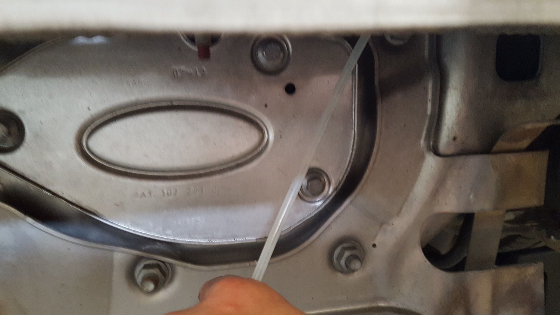
I found this pic that shows how 991-111-492-00 connects the right valve to the holder, which is screwed into the top bolt, and guides the vacuum through the oval heat shield.
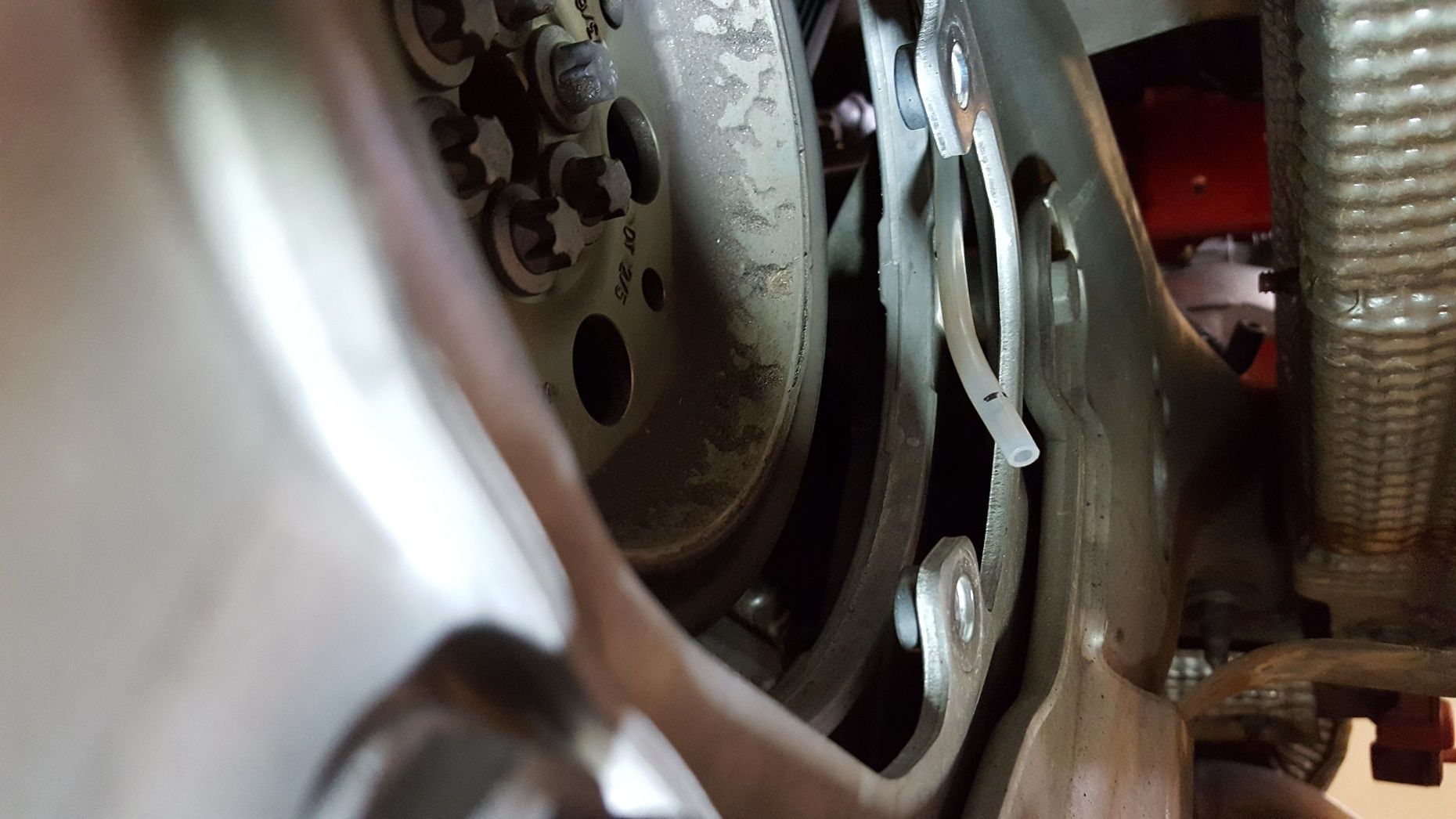
I removed the oval heat shield to see what's behind it and what the tube will have to be routed through or around to get to it. There's very little room, and I believe that I'll need to route the tube between these two pieces so as to stay away from whatever that circular thing is (which I'm guessing rotates at high speed). I've changed my mind from post #19. I think the tube will need to run on the back side of the frame, so it can come out behind the oval heat shield.
Alright, I've got all the parts. Since no one has confirmed that the routing I showed in post #26 is correct, I guess I'm going to have to assume that's correct, and will proceed with that route. I can't imagine the OE installation routes the vacuum line somewhere else.
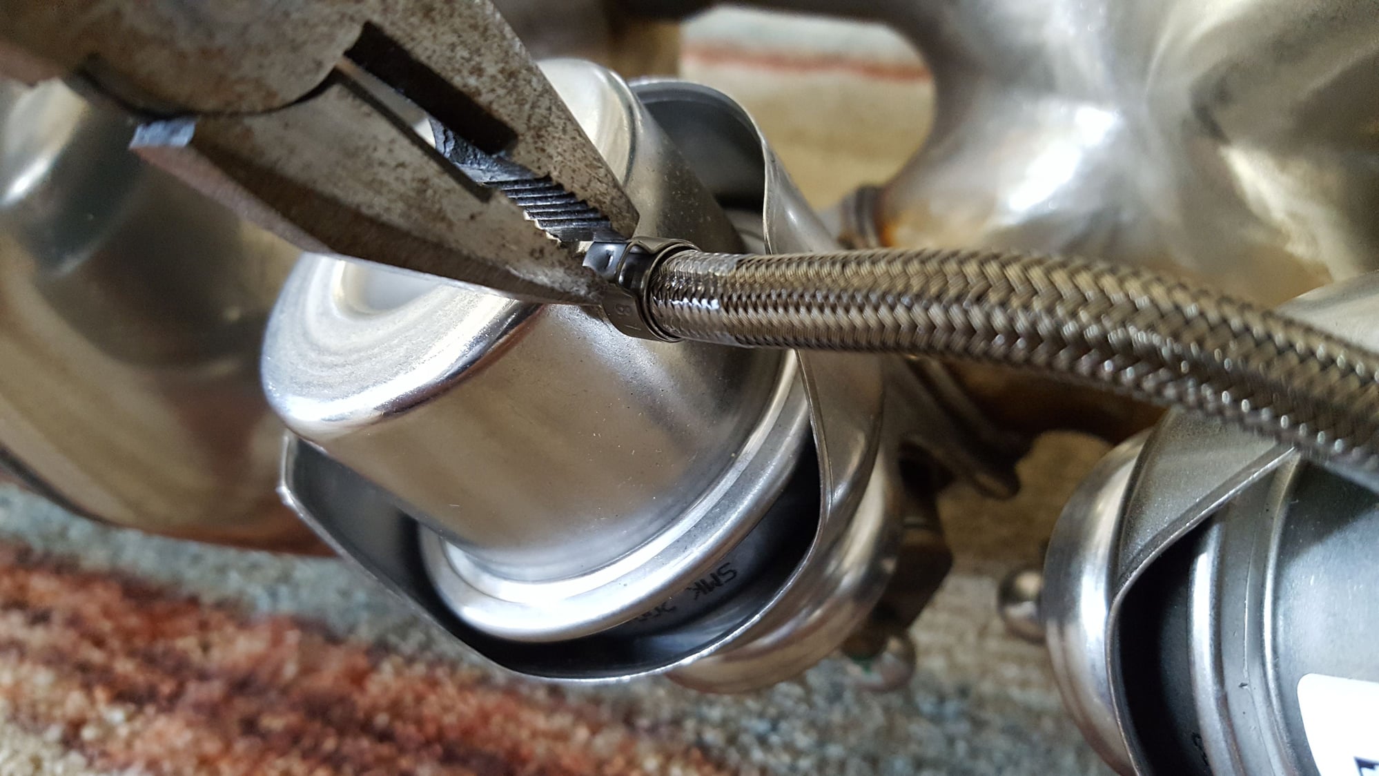
Can anyone tell me how I'm supposed to crimp these steel vacuum lines? Do I just use a pliers to crush the little extra metal that is sticking out from the circumference of the line? Like this?

 06-28-2016, 01:27 PM