When you click on links to various merchants on this site and make a purchase, this can result in this site earning a commission. Affiliate programs and affiliations include, but are not limited to, the eBay Partner Network.
On 981s there is an electronics module attached between the battery ground post and the chassis and it contains low voltage loss current measurement electronics. My guess is that the external ground point is two fold: one to prevent a spark that MIGHT set off battery gasses; second to protect the current measurement electronics.
Last year I purchased a flooded 981 Boxster and it arrived with a dead battery. I had same issue getting trunks open. In my case, for the rear trunk, I was able to put 12V on the actuator wire out of the RBCM. For the front trunk, the red fuse box jumper worked only with the key/remote as the FBCM was OK but the RBCM was toast (the car had water up into the bottom of the power seats). The car arrived with the carpet dry but I pulled out three gallons of water via a dehumidifier, taking over three weeks. The cavities under the carpet can hold a lot of water. I did not get the mildew smell under control until the dehumiidifier removed the remaining water.
In my case, the prior owner pulled the door sill switches while the RBCM was under water and high current flowed on these (switch) signal lines and melted the wiring. The previous owner must of seen smoke and pulled up the door trim and cut off the four wires to the switch. This necessitated me getting a new trunk switch assembly and used wiring harness and pulling the switch connector and four wires and grafting them into the car's wiring harness. Six modules total were fried and the passenger seat.replaced. If you ever need to know how to non-destructively get a power seat out when it won't move, ask me. It took two weeks to figure it out (in cold, snowy January). Car has been back on the road since June with no problems.
V6
Not to derail the thread but kudos to you for being smart enough to bring a cayman back to life.
Also, thanks for the info on the � electronics module � between the battery ground post and chassis grounding point.
I�d really like to get the set up that AntiGravity is suggesting and as they�ve always provided good info on the forum I�d love to hear their response.
Would it be possible to hook the negative wire to the Porsche approved � grounding point � as the owners manual specifically says not to jump a Cayman from the negative battery terminal. If you think this isn�t necessary can you please tell me why as I�m not that technically inclined and I�d be afraid to fry my electronics.
Also, is the blue connector your using ( the end that plugs into the MicroStart � weather proof or do you provide a cover for it so it wouldn�t corrode ? Again, if this isn�t necessary just let me know.
Great questions... proves I miss thinking of some things. Also I will never say to go against a manufacturers statement, though it is a typical dislaimer.
There is no reason why you couldn't hook up the Neg cable on the harness we are developing to the negative ground post. Except I don't know if our cable would then be long enough to reach that point. But thanks for bringing that up. Maybe it could be rigged with a hose clamp holding the fork-terminal to the post.
Now I will say my opinion on the Harness kit in relation to this. With the Harness kit being hardwired to the battery there is no potential for Spark when you plug in the MICRO-START because you are not having to put clamps onto the Battery posts themselves which is when the sparking normally occurs. Additionally the MICRO-START even if fully charged is usually only at 12.2v, it is a Lihtium Polymer battery that is a different chemistry than our Lithium Starter Battery... it sits a little lower in voltage actually. But when plugged into the Harness it will then just be providing voltage/current to the battery so you can operate the frunk switch. You would not actually have to Jump Start the car if you don't feel comfortable with it. You could at least open the frunk and if you wanted to jump start using the Ground Rod then you could use the MICRO-STARTs clamps that come with the MICRO-START kit to do the jump start part with.
Regarding a cover for the Blue EC5 tip... yes it will come with one to provide some weather resistance.
On 981s there is an electronics module attached between the battery ground post and the chassis and it contains low voltage loss current measurement electronics. My guess is that the external ground point is two fold: one to prevent a spark that MIGHT set off battery gasses; second to protect the current measurement electronics.
Good answer... I have to agree though I've never fully understood the exact reasoning.
I know newer cars have an IBS (Intelligent Battery Sensor) on either the negative or Positive Battery cable clamps.... that plastic housing attached to the clamp you attach to your car battery. It measure voltage and current coming in and out of the cars nowadays and relays that info to the Alternator so the Alternator knows to charge or not. Nowadays cars have this system because they need to meet Emission, and Mileage Standards, and by allowing the Alternator to not be charging so often it reduces drag on the Motors there for increasing mileage and lowering emissions even though it might only be very slightly. So nowadays cars rely much more on the battery to provide the initial energy for much of the cars accessories like the Fans, A/C and other stuff will now pull on the battery first and draw it down and then when it get into a lower discharge state throw a charge out to it.. but it is not like the older cars where the Alternator was charging most the time.
That seems to be a pretty standard recommendation in most cars, but honestly I can't see much difference as the battery ground most likely goes straight to the chassis. I suspect it could be to prevent sparks from igniting battery fumes on connection/disconnection.
Great questions... proves I miss thinking of some things. Also I will never say to go against a manufacturers statement, though it is a typical dislaimer.
There is no reason why you couldn't hook up the Neg cable on the harness we are developing to the negative ground post. Except I don't know if our cable would then be long enough to reach that point. But thanks for bringing that up. Maybe it could be rigged with a hose clamp holding the fork-terminal to the post.
Now I will say my opinion on the Harness kit in relation to this. With the Harness kit being hardwired to the battery there is no potential for Spark when you plug in the MICRO-START because you are not having to put clamps onto the Battery posts themselves which is when the sparking normally occurs. Additionally the MICRO-START even if fully charged is usually only at 12.2v, it is a Lihtium Polymer battery that is a different chemistry than our Lithium Starter Battery... it sits a little lower in voltage actually. But when plugged into the Harness it will then just be providing voltage/current to the battery so you can operate the frunk switch. You would not actually have to Jump Start the car if you don't feel comfortable with it. You could at least open the frunk and if you wanted to jump start using the Ground Rod then you could use the MICRO-STARTs clamps that come with the MICRO-START kit to do the jump start part with.
Regarding a cover for the Blue EC5 tip... yes it will come with one to provide some weather resistance.
Thanks for the response.
I�m going to take a look at how the � ground point � Is attached to my Cayman and will try to figure out how to attach the kit you are making safely and cleanly - I hope that the ground point is bolted it.
Agsin, hope to see this battery lead extension kit realwased soon as it could prevent a lot of � pain � in case of a dead or weak battery.
Hello folks!
I don't want to create a different thread since my issue is similar, but at the same time is not.
Just got a 07 Cayman few days ago and now I need to go through some of the issues it has and one of them is a buttons by the drivers door for the front trunk and rear trunk
The issue is - they doesn't work. And while I'm pretty certain why the button for the rear trunk doesn't work (I need to replace the rear control module under the driver seat, and if you are selling one - let me know ), I can't logically describe why the frunk button (by the door) doesn't work. Here is a dilemma - button on the keyfob opens the frunk. Lever in the frunk boot - opens the frunk.
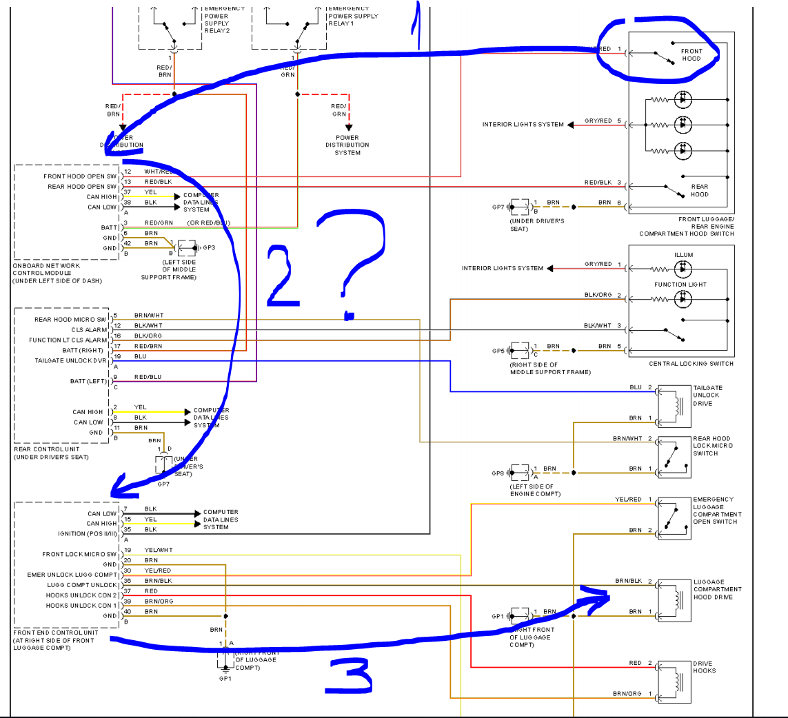
Based on the schematics the front trunk release button is connected to the network control module, which is connected via CAN to front control module.
I did go ahead and connect the diagnostic tool. Besides the scanning it has some actuation tests.
When I connect to the central network module and read the status of the button - it changes from inactive to active when I press the button. So the button works and definitely send the signal to the network module.
When I connect to the front control module (in the front trunk) and send the command from the scanner to open the latch - it opens. When I check the status of the button in that module - it always shows inactive. So it kinda doesn't receive the "open" signal from the central network module. But it receives the signal from the keyfob and opens the front trunk.
Is it a central network module that doesn't send signal to to the front control module or it is a front control module who doesn't "hear" the signal from the network module? Or is it somehow related to the rear module (that I need to replace) that technically have nothing to do with the front trunk latch?
Ideas?
If you look at the diagram the ground at GP7 for the frunk switch is provided by the rear control unit. The switch has no ground and therefore is not triggering the input on the network control module.
I wouldn't agree. GP7 is the "ground nut" next to the rear control unit. They (rear control unit and buttons) share the same ground point. Unless I'm missing something
And I wrote, that when I press the button - it actually triggers the input on the network control module (when I check the input state on the diagnostic). What's not being triggered is the front control module. Which means that either network module is not sending the signal further to the front control module, or the communication between the modules is lost or the front control module is not receiving the signal from the network module. I will try to shoot the video with diagnostics tomorrow.
Then my interpretation of the drawing is wrong. So you see the input trigger from the release button but the signal to trip the latch relay never happens. So the switch triggers the network module. The network module communicates over the CAN bus to the front end module and the front end module triggers the relay for the frunk latch. So if the network module is sending the signal to the front end module you should see pin 36 go low or high depending on its non-triggered state. Correct?
Then my interpretation of the drawing is wrong. So you see the input trigger from the release button but the signal to trip the latch relay never happens. So the switch triggers the network module. The network module communicates over the CAN bus to the front end module and the front end module triggers the relay for the frunk latch. So if the network module is sending the signal to the front end module you should see pin 36 go low or high depending on its non-triggered state. Correct?
Exactly. Right now I just can't figure out which out of 3 chain members is responsible for this miscommunication - network module, CAN bus or front module. It may be the problem with the can bus, since network module sees the button, and front module respond to the keyfob trunk release. I may be wrong though. I will try to shoot the video today.
A little update:
It looks like that the rear module is required for the frunk button to operate! I did purchase VW Touareg comfort module ($11), took some components out of my flooded module (the components turned out to be fine) put it into the touareg module and voila - buttons are working, spoiler is working, rear latch is working. That's a fuggin cheap fix Will be shooting the video later.
I applaud your skills and love the fact that you fixed your problem for $11.

 11-20-2018, 02:00 PM


 ), I can't logically describe why the frunk button (by the door) doesn't work. Here is a dilemma - button on the keyfob opens the frunk. Lever in the frunk boot - opens the frunk.