When you click on links to various merchants on this site and make a purchase, this can result in this site earning a commission. Affiliate programs and affiliations include, but are not limited to, the eBay Partner Network.
Hi Fritz, totally understand, thank you very much for trying. It must be in super tight for just the blue cap to come off because my Control Unit came out of the socket reasonably easy but the blue cap took a little bit of effort once out.
If the Control Unit was reasonably priced I�d just replace it but as you say it�s pricey and I�m not convinced it�s the problem if no tach signal is getting to the socket of the Control Unit.
So question remains; why is there a signal at T15 but not at the socket? I�ll put my thinking cap back on!
Might be a long shot but the magnitude of the frequency voltage is unknown unless you use an oscilloscope to measure accurately.
Example
Hz @ 2VDC
VS
Hz @ 12VDC
Try measuring VDC where you are picking up Hz.
might be inductive pickup being read on the multimeter but not enough voltage for the early 90s input to the dash instruments. A long shot but possible?
I think this approach doesn't go any further. Firstly, it is an inductively generated AC voltage and not a DC voltage. And secondly, the decisive signal for speed detection is not the voltage but the frequency or its change and for this we have a "known good" value, namely 45 - 50 Hz at idle.
I believe the only speed sensor reference for RPM to be an output from the EZ69 (TD-16, BK/VI), then it passes to several control units and to the Bosch hammer test port. (Terminal 14, TD. Could also try Fritz�s suggestion of hz on a multimeter or oscilloscope here in the passenger footwell)
If your hammer sees a RPM in the pulse duty screen then your interface module has likely failed or your wiring. Check end-end with an ohm meter, devices disconnected at each end to prove the wiring is not faulty.
Would be very coincidental for the RPM/Pressure signal circuits to fail at the same time.
My annotations are just artifacts from previous troubleshooting, they can be ignored.
Hello Do you have the complete workshop Manual from a Turbo in pdf
Another update! After running a separate ground wire from the back of the car and more testing, I was able to get a tach signal from the HZ socket the Control Unit plugs into. But I still couldn't get a signal if using the ground (Term 31) in the socket. Could only get it if using a different ground and the signal was a bit erratic. Also tried more tests with the Control Unit plugged in but nothing worked.
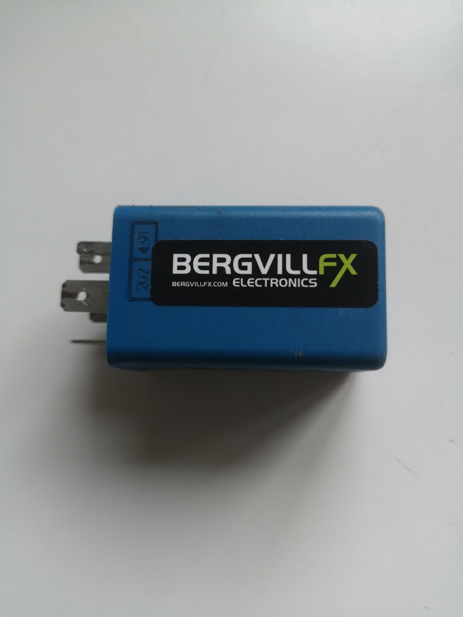
Then it dawned on me that Tore fixes all manner of electrical components for the 964/993 so I reached out to him. Lo and behold Tore confirms he has a bespoke test bench for these units and is able to repair them!
I got hung up on not getting a tach signal at the socket itself when I could get it at T15. However, according to Tore "The tachometer input signal will not be possible to measure on the socket without the blue control unit installed. The blue control unit has an internal resistor that is necessary as a pull-up load on the tachometer input signal. If you try to measure this input signal without the blue control unit installed, you have to introduce such a load resistor. There will be no voltage to measure if the control unit is not present."
I was unable to get a signal with the Control Unit installed because it had developed a fault "the tacho/turbo control unit had the normal component ageing defects, a couple of capacitors had failed, and killed the internal power supply circuit. I see this often occurring in our ageing cars".
Control Unit is now back in the car and tacho and boost pressure signal reading as per normal. Thanks again to Tore, his knowledge, fast responses and overall service really is outstanding: BERGVILL F/X (bergvillfx.com).
Thanks also to Fritz, Nyx and others for their advice and suggestions. Much appreciated, I got there in the end!
Hi, the interface was high on the list of suspects, but I've never heard of it failing. I wouldn't have thought of Tore B., even though I sent him an 997 amplifier to be repaired three weeks ago.
Anyway, the fact that everything has now come to a solution is thanks to your persistence and your efforts, the success is deserved. Thanks for the update.

 06-20-2024 | 04:46 PM