When you click on links to various merchants on this site and make a purchase, this can result in this site earning a commission. Affiliate programs and affiliations include, but are not limited to, the eBay Partner Network.
awesome guys - Gus & Wallra - that's great info. (Occams razor applies as usual - see below)
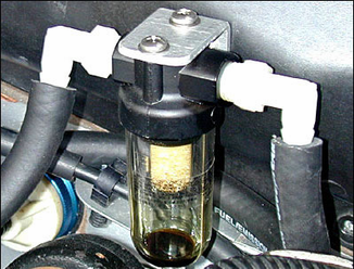
Gus I found one very similar to this (just a bit prettier) which I'll try and see how much it collects and if it allows enough gas through but it has a high flow rate and 10bar capacity so it seems good. Only issue is the 70 degree C limit for the plastic, but shd be ok in the bay as long as the fumes aren't 100 of something.
Wallra (always nice when a pro weighs in - thanks!) my one way wasn't blocked but I had the two breather pipes (a - to air filter housing and b - to throttle body) reversed so once I removed all the pipes, checked them, cleaned them and re-attached them I found the twist in the transition through the inner wheel arch wall and reversed them and ....
!!VOILA ... no push back in the filler neck and in fact there is such suction in the filler neck now (even when the car is idling) that the oil filler cap can't come off without a proper pull even after it's completely loosened. That effectively means the crank is in a vacuum and the new rings are sealing well I recon.
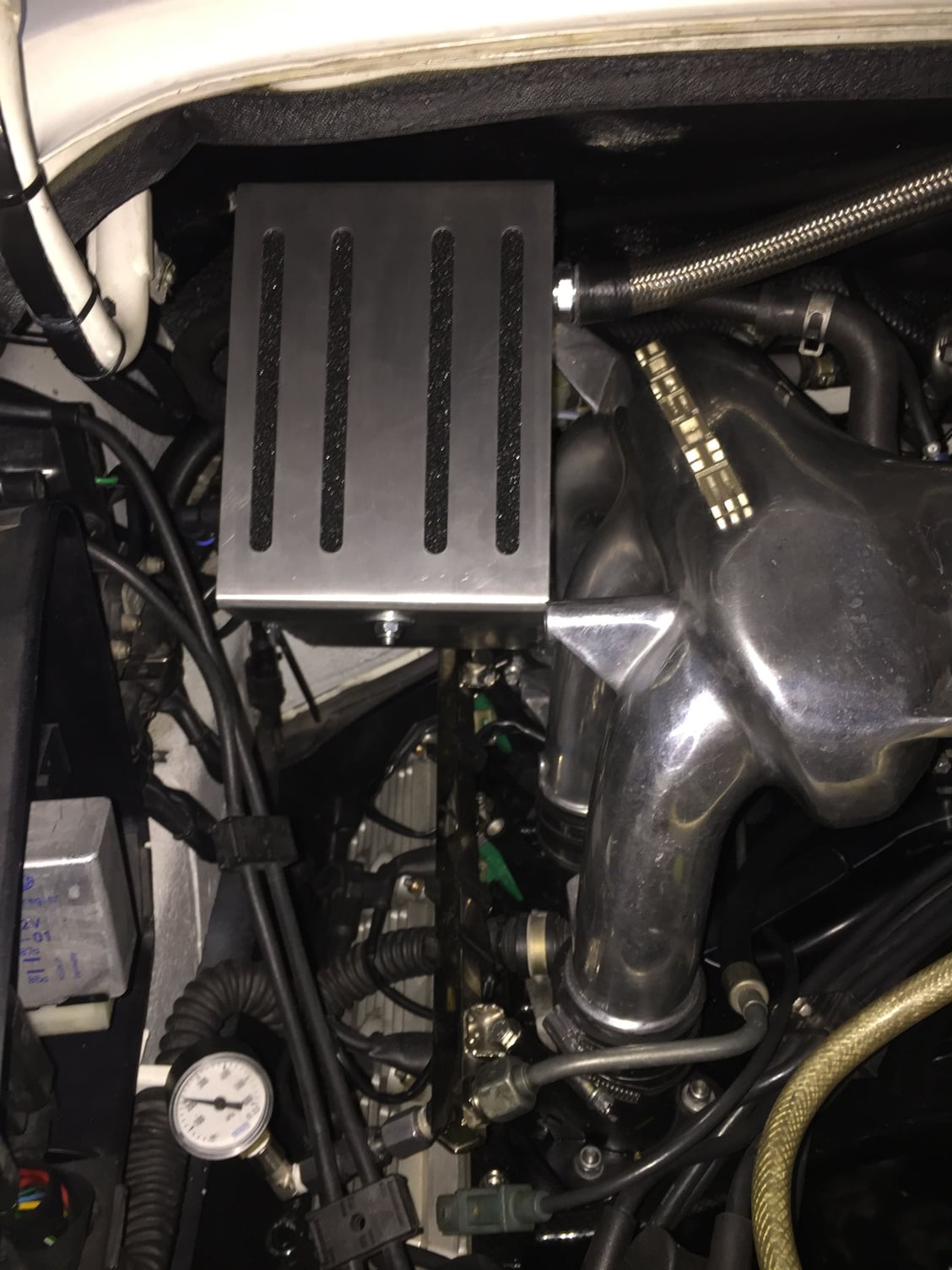
For those reading the whole thread .. I'm referring to gus' yellow & blue pipes above the crankcase breather pipe fitting on the oil tank - see pics above.
Due to this suction my catch can is however still empty but after the tuning session on the M84 it might get some splash - we'll see. I think I'm pretty close to abandoning the catch can in favor of the oil sep only but we'll see post some spirited driving.
Edit: NB: the suction was not correct - see further down
Here is the manual I down loaded it than printed a copy. http://early911nzdownloads.yolasite....op-manuals.php I had a chatch can on my supercharged vw jetta vr6 pain in the *** keeping it clean. in the winter it would freeze up. was always full of white **** from concatenation.
I see your going to be tuning the m84 I'm going to be doing the electromotive TEC gt200 because I'm installing coils on plug setup with map sensor so no more distributors, air flow meter.
Last edited by wallra; 04-19-2017 at 04:32 PM.
Reason: added
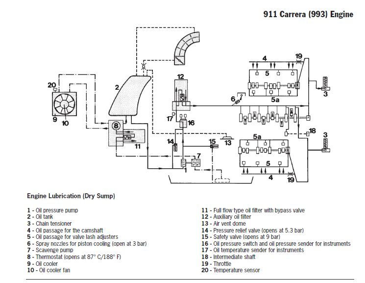
HalV - great diagram - certainly clears oil system pipes up. Great find. Makes it very clear that there is no filtered oil going directly into engine. Only oil from tank, so need to stay on top of what goes in. Now, how do we change that? Is adding the turbo or 993 second filer on right front (by trans) of engine the only solution??
Here's some descriptive text that goes with the diagram:
For filtration of the engine oil, a full-flow filter (11) is
included in the return circuit, and a small auxiliary filter
(12) is located at the inlet to the engine to protect the
valve lash adjuster elements against contaminates in the
oil. Both of these filters have to be replaced every 48,000
km/30,000 miles. The engine oil has to be changed every
24,000 km/15,000 miles. Approx. 9 liters are required for
an oil change.
Ok - now I am really jealous - not only does the 993 engine have a pre engine oil filter they have an oil spray to cool the pistons. Now that would be something work installing.
So now I have 2 oil improvements to do - oil console for second filter and oil sprayer when I split the cases.
I see your going to be tuning the m84 I'm going to be doing the electromotive TEC gt200 because I'm installing coils on plug setup with map sensor so no more distributors, air flow meter.
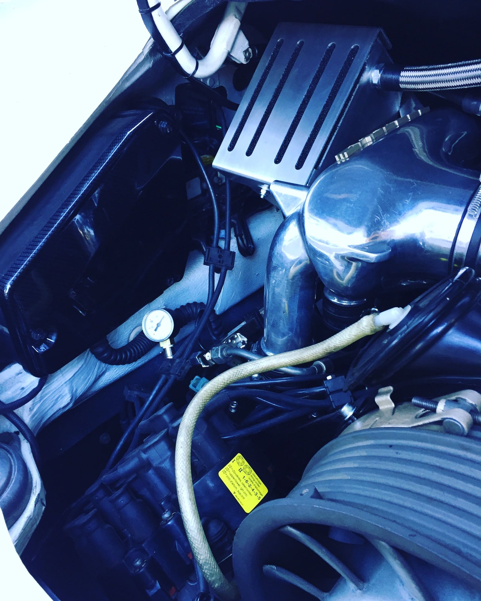
Yes ... its going quite well re idle and LWFw & breathing catch can - pics later but bigger is better to prevent push back into filler neck etc..
Originally Posted by HalV
I'm not sure if this helps but I saw this diagram from the AfterSales_Training manual that I thought might be useful.
Thanks Hal - that is the same pic in Adrian's book but I thinks its WRONG ... see line 13 & 14 to filler neck - where do we have that in the 964? We have the two breathers to the intake not one to the filler neck as in older 911s, right? Also our oil filler line doesn't enter at the top, it emerges from chassis about a 1/4 way up the tank from the bottom side ie close to #2.
So line 14 should actually be drawn to intake 16 on the air filter/afm side of the intake (the other line is shown post butterfly I assume but it isnt that clearly detailed imo) and not go near the filler neck 13. 17 should also be called crankcase breather as that's how its referred to elsewhere
1. bigger pipes for breather is better .. 19mm min
2. 1L is minimum size .. went with 1.8 as I had the space
3. going to keep it in engine bay for now for easier monitoring then inside fender opp. side from Oil tank later?
4. best to have neutral pressure in tank so the breather tank 19mm pipe has the 6mm restrictor (in the tank connection) and the small restrictor goes to intake to remove the pressure in tank
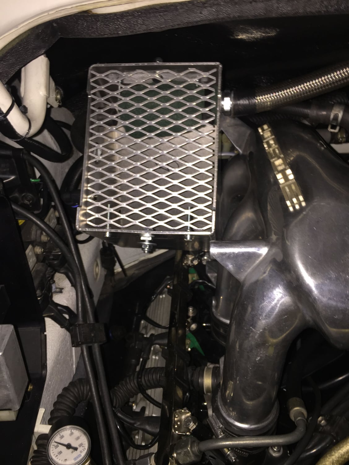
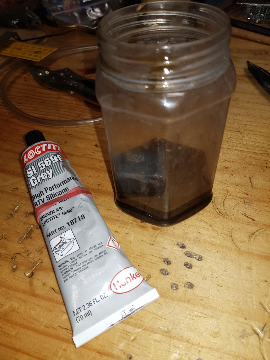
just to add some data - drained my two oil catches (the small one on the vacuum side) and the larger one on the left side as shown above.
After roughly 2,800km I drained 3 teaspoons of oil from the small oil/air separator.
The drain plug on the big breather tank yielded more but not a massive amount.
Either way it makes me happy to think this dark stuff is not in the intake.
Oil was thoroughly drained 3,000 km ago with a top end rebuild.
HiWind - sorry for slow response- major work on car right now- this is the current oil breather hose configuration that I have and it appears to work without back pressure issues.
1. Crankcase breather hose to tank - no change over stock set up.
2. Tank vacuum line (after bfly) ran this line through a closedoil separator tank about size of beer can. It is not vented to the outside air. Is designed to pull reassure from tank but remove any oil before intake manifold.
3. The tank vent line (pre bfly) - I plugged this opening before the butterfly. Then ran the line from the oil tank to a catch can that is vented to the outside air. So this line is open to standard atmospheric pressure.
I have internal fluid level view lines on both catch cans so I can monitor fluid levels.
I have run this system for several DEs with good results. NO oil bow back or leaks from the tank at all.
May not be the solution for all. But I went this route because of the oil that was migrating into the intake. Since I run a Varioram - oil was then leaking out the bottom flap control fitting. Not much or enough to worry about - but enough to oil up the upper engine area.
Hope this helps
Hi Gus, I have a question regarding to your config. I am not sure in 964 but in my 993 non Varioam, will your configure cause a vacuum leak?
What I mean is that the Tank vacuum line (after bfly) will loss its vacuum from your open air oil catch can via the oil tank.


 04-19-2017, 03:08 PM
 - see below)