When you click on links to various merchants on this site and make a purchase, this can result in this site earning a commission. Affiliate programs and affiliations include, but are not limited to, the eBay Partner Network.
My speedometer has printed 4052 on it, this means that it is designed for 4052 pulses per kilometer. The speedo VSS output signal is a variable pulse-length signal, but with the same frequency as the input from the ABS control unit.
Cheers,
Tore
My speedometer has printed 4052 on it, this means that it is designed for 4052 pulses per kilometer. The speedo VSS output signal is a variable pulse-length signal, but with the same frequency as the input from the ABS control unit.
Cheers,
Tore
Great info and it confirms the theory.
4052 pulses divided by eight pulses per revolution = 506.5 revolutions per kilometre = a wheel circumference of 1.974m, which is very close to the 964 OE tyre size of 1.984m. You have a 993, correct? That could explain the 0.5% difference.
With analogue components in the original controller there is going to be some variance in exact trigger levels.
First trigger level is 7km/hr (8Hz) to detect the speed signal presence.
Normal extend trigger is 80km/hr (90Hz)
Emergency extend trigger is 116km/hr (fed from ABS sensor)
FYI this post contains the ABS frequency conversion info https://rennlist.com/forums/964-foru...-location.html The left front ABS sensor provides the signal which is converted from 45 pulses down to eight for use in the controller. The controller unit would require an input of 130Hz for 116km/hr so the raw ABS input into the frequency converter must be 731Hz
Thanks.
I have an adapter cable for use with the extra spoiler unit as well.
However, I have never needed to repair these. It is most probably always dormant in the relatively few cars that have this installed.
As it is not used, it is not exposed to the same wear as the main unit, and it is of a different and more reliable electronic/mechanical construction than the main unit.
Cheers,
Tore
That makes sense based on the photos I�ve seen of the inside of one e.g. no relays.
My spare controller produced the same fault on two cars today so I�m looking forward to diagnosing that. It works as it should but the warning light is going off when the car corners. I suspect a relay.
For those of you that worry about such things. All of the transistors and ICs are still available. I've sourced new relays as well, but they are still in the post.
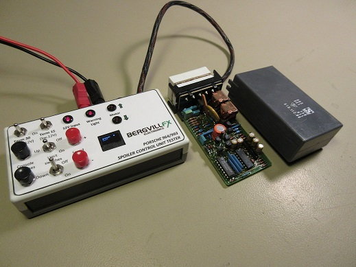
Making good progress. I have built an in-circuit transistor and diode tester. I have also built a test rig, and thanks to another 964 owner I was able to source the original spoiler loom with plugs for main controller and auxiliary. The only hurdle I’ve struck is replicating the warning light. Tore, is there any info on what signal the controller is sending to the central informer?
The warning light is an open collector transistor output, and pulls to GND when activated.
Cheers,
Tore
Thanks, I changed the LED input to get a proof of concept and it works! Just the speed signal to go.
FWIW I have two unserviceable controllers to work on. Both actually control the spoiler correctly but one has constant alarms and the other alarms when going around corners. Bizzare
Test rig is fully functional now. I have a signal generator producing 8 volt square waves. The lowest frequency it can generate is 9Hz, which instantly exstinguishes the warning light. My spoiler unit extends at 80Hz, which is about 10% lower than expected. Next I will log all of the logic functions.
I think the error in the extend frequency is due to the fact that the speed signal input is not a 50% duty cycle square wave. It is a pulse stream made up of a 2.1 ms "off" time with a variable "on" time. See the pics of the speed signal at 40 mph's and at 60 mph's. This would effect the Cx/Rx charge coming out of the MC14538 chip on the module. See hand-written schematic of the module - notes are mine. Components are in similar position as on the module. Let me know if you see something not right and I'll correct it!
I think the error in the extend frequency is due to the fact that the speed signal input is not a 50% duty cycle square wave. It is a pulse stream made up of a 2.1 ms "off" time with a variable "on" time. See the pics of the speed signal at 40 mph's and at 60 mph's. This would effect the Cx/Rx charge coming out of the MC14538 chip on the module. See hand-written schematic of the module - notes are mine. Components are in similar position as on the module. Let me know if you see something not right and I'll correct it!
Just at the right time. Great work. Thanks. I have two controllers with faults to fix. Both operate correctly with the speed signal, but both have warning lights constantly on. It looks like my first test is on the voltages at pins 8, 9 & 10 of the LA6324 IC
Edit: The voltages at pins 8,9 & 10 are the same on the good and bad units both when there should and shouldn’t be warning lights. Looks like my faults are between the output of pin 8 on the LA6324 IC and the plug output. Luckily there isn’t much there.
The voltages were the same across all three controllers. As I wrote above, the faulty units appears to be faulty warning circuits downstream of the LA6324 IC.

 01-11-2019, 06:34 AM