Help - unidentified crumbling connectors
#31
Pro
Thread Starter
My crumbling sensor connectors issue is behind me now and I am pleased with the results. It took some time to figure out what parts were needed and where to get them and also to come up with a procedure for the repair.
I will post here what I learned so that it might save others some time and trouble and allow them to learn from my mistakes.
First off, a few words as to why I went to the trouble of sticking with the old style connectors.
The OEM connectors are molded permanently onto the sensor wire and normally you would have to buy and install a new sensor. To make matters worse Porsche changed the design of the connector which makes it incompatible with the mating connector and thus requires a modification to your main wiring harness. Porsche no longer sells the old style sensors. Also if your sensor is OK it seems a shame to replace it when a connector swap can allow you to retain your working sensor and maintain the originality of your car. Also, some of these sensors are very hard to replace without dropping the engine, so you save yourself the time and frustration of installing new sensors, not to mention you save some $$.
Others who have tried to fit the new style sensors on their 964’s have complained that the wires are not long enough and alternate routing is required and in some cases the wire gets bent at a sharp angle where it exits the connector. Not good. The reason for these shortcomings is that the new sensor is designed for the 993 not the 964.
Some vendors claim to still be able to supply the old style sensors and that is fine if your old sensor died, but in my case the sensors were good so I chose to just swap out the connector. After lots of searching I found a good, reliable supplier for connectors that fit the mating connectors on the harness, eliminating any need to cut and splice into the main wiring harness.
TE Connectivity is the manufacturer of all the needed components and I sourced them from their distributor, Mouser Electronics Inc. (www.mouser.com or www.mouser.ca ) (Pronounced Mowzer).
All part numbers specified are TE numbers. Prices are in Canadian dollars.
The connector you need for each sensor is:
1-962581-2 $6.28 each
The tabs that fit inside the above connector are:
1-962916-2 (these are silver plated) $0.88 each
The blue wire seals that keep dirt and water out of the connector are:
828904-1 $0.32 each
828922-1 $0.15 each (this is a sealing plug with no wire hole. You will need this to plug the third hole in the connector when you are wiring up a two-wire sensor)
I could not source a rubber boot for the connector. I even called tech support at TE and they advised that they do not make a rubber boot for this connector. I found a very close match but no amount of stretching could get it to fit. I even tried cutting it to fit and that attempt failed. The solution was to use heatshrink or self-sealing tape or both.
To get this connector to fit perfectly into the support bracket in the engine bay requires slight mods. The groove in the connector needs to be made 0.030” wider and 0.020” deeper. The groove should end up about 0.094” wide so a 3/32” diameter end mill is perfect. I cut mine on a drill press with a cross-sliding vise. If you are good with a file or a Dremel tool, that can work too.
Here is the procedure that I used to install the connectors once the groove had been re-shaped:
Procedure to install 1-962581-2 to 964 engine sensors.
(includes Crank, Knock and CHT sensors)
1) Remove old connector. To give yourself as much wire as possible, I recommend crushing the old connector with a C-clamp and then clip the tabs off leaving as much wire as possible.
2) Strip at least 2.5” of the outer insulation from main casing. This is quite important as the blue wire seals are not guaranteed to be watertight if the exit angle of the wire exceeds 5 degrees. Ask me how I know this.
3) Peel back the braided shield. Use a dental pick or similar tool to unbraid the shielding. Work slowly from the cut end of the wire until you have close to 2.5” unbraided. Twist these braids tightly to form a wire.
4) Slide the blue wire seals onto each of the three sensor wires. Make sure the seals go on in the correct direction. The small diameter of the seal needs to be closest to the connector. The CHT sensor only uses two wires and since the connector has three holes you need to plug the middle hole. This can be done with a special wire seal that has no wire hole but I did not know these were available. See above for the part number for the “sealing plug”. Since I did not have a sealing plug, I just inserted a short piece of wire into the hole to keep water from going in. If you decide to use silicone seal anywhere on this connector make sure you use the stuff designed for electrical connections. Anything else can be corrosive.
5) Strip 5mm of insulation from small wires. The strip length is quite fussy so take your time to get it right. These wires are equivalent to AWG 20. Use the smallest wire stripper you have since you won’t have much working space in the engine bay.
6) OPTIONAL - Slide small heatshrink over stripped wires and over main wire. If you opt for this step, make sure the shrink ratio of the heat shrink is adequate. You might need a 4:1 ratio. For now push the heatshrink well out of the way.
7) OPTIONAL - Slide large heatshrink over small heatshrink. This will cover the connector and the smaller heatshrink. For now push the heatshrink well out of the way. If you take this step, try to find heatshrink to match the color of the mating connector to avoid incorrect assembly of the connectors as all three are identical.
8) Cut the tabs (the electrical contacts) from the band and preform the crimps by hand unless you have the ultra-expensive special crimping tool. I found that using small, clean drill bits and a small pair of pliers, allowed me to pre-form the crimps quite nicely. Leave the pre-form enough oversize to allow insertion of the stripped wires that are 0.8mm in diameter. I started with a #43 drill bit and finished with a #54. I also pre-formed the crimp for the blue wire seals in the same manner but with a #27 drill bit. It is much nicer to do all this work at the bench as opposed to reaching so far into the engine bay.
9) Now the hard part of working in the cramped engine bay.
Double check to make sure the blue wire seals and heatshrink (if used) have been installed onto the wires and then manually attach and crimp the three tabs onto the wires. I used a normal automotive crimping tool to crush the pre-formed crimp onto the stripped wires. It’s a good idea to bench test this on a scrap tab with a scrap piece of wire first.
10) Solder all connections. I found it helpful to apply duct tape to keep the wires from moving around too much while crimping and soldering.
11) Slide wire seals into place and crimp with small pliers.
12) Slide tabs into the correct positions in the connector making sure they lock into place. See below for positioning information. The wire seals will put up a lot of resistance as they enter the connector so at that point, turn the connector over and pull directly on the tab instead of trying to push on the wire. In engineering school they teach you that you cannot push on a rope. Good lesson.
13) OPTIONAL – If you opted for this step earlier, now is the time to slide the small heatshrink over the wires and apply heat.
14) Apply self-sealing tape to cover the connector and the wires.
15) OPTIONAL - If you opted for this step earlier, now is the time to slide the large heatshrink over the small heatshrink and apply heat.
16) If you did not use heatshrink and want to color-match with the mating connector, you can apply colored electrical tape over the self-sealing tape, or try to source colored self-sealing tape.
17) Now you are ready to install the fully assembled connector back into the support bracket.
Tab positions can be found and confirmed in 993 KD-NR. 97 50 41 and in factory electrical diagrams found in the workshop manual. Please triple check before you insert the tabs into the connector as they are not easy to remove once they lock into place. With great effort and the assistance of two small paperclips I was able to remove one tab but this was done at my desk on a test connector. Attempting this in the confines of the engine bay might make one suicidal.
For the Crank Sensor (Pulse Sender)
#1 = White (conductor is 0.5 sq. mm and 0.8mm diameter ) = AWG 20 ( I believe all sensor wires are the same size)
#2 = Brown
#3 = Shield
For the CHT sensor
#1 = Black/Red
#2 = Dummy
#3 = Brown
For the Knock sensor
#1 = White
#2 = Brown
#3 = Shield
I have included a few photos in the next posting. If you have any questions you can PM me or post here.
I will post here what I learned so that it might save others some time and trouble and allow them to learn from my mistakes.
First off, a few words as to why I went to the trouble of sticking with the old style connectors.
The OEM connectors are molded permanently onto the sensor wire and normally you would have to buy and install a new sensor. To make matters worse Porsche changed the design of the connector which makes it incompatible with the mating connector and thus requires a modification to your main wiring harness. Porsche no longer sells the old style sensors. Also if your sensor is OK it seems a shame to replace it when a connector swap can allow you to retain your working sensor and maintain the originality of your car. Also, some of these sensors are very hard to replace without dropping the engine, so you save yourself the time and frustration of installing new sensors, not to mention you save some $$.
Others who have tried to fit the new style sensors on their 964’s have complained that the wires are not long enough and alternate routing is required and in some cases the wire gets bent at a sharp angle where it exits the connector. Not good. The reason for these shortcomings is that the new sensor is designed for the 993 not the 964.
Some vendors claim to still be able to supply the old style sensors and that is fine if your old sensor died, but in my case the sensors were good so I chose to just swap out the connector. After lots of searching I found a good, reliable supplier for connectors that fit the mating connectors on the harness, eliminating any need to cut and splice into the main wiring harness.

TE Connectivity is the manufacturer of all the needed components and I sourced them from their distributor, Mouser Electronics Inc. (www.mouser.com or www.mouser.ca ) (Pronounced Mowzer).
All part numbers specified are TE numbers. Prices are in Canadian dollars.
The connector you need for each sensor is:
1-962581-2 $6.28 each
The tabs that fit inside the above connector are:
1-962916-2 (these are silver plated) $0.88 each
The blue wire seals that keep dirt and water out of the connector are:
828904-1 $0.32 each
828922-1 $0.15 each (this is a sealing plug with no wire hole. You will need this to plug the third hole in the connector when you are wiring up a two-wire sensor)
I could not source a rubber boot for the connector. I even called tech support at TE and they advised that they do not make a rubber boot for this connector. I found a very close match but no amount of stretching could get it to fit. I even tried cutting it to fit and that attempt failed.
 The solution was to use heatshrink or self-sealing tape or both.
To get this connector to fit perfectly into the support bracket in the engine bay requires slight mods. The groove in the connector needs to be made 0.030” wider and 0.020” deeper. The groove should end up about 0.094” wide so a 3/32” diameter end mill is perfect. I cut mine on a drill press with a cross-sliding vise. If you are good with a file or a Dremel tool, that can work too.
Here is the procedure that I used to install the connectors once the groove had been re-shaped:
Procedure to install 1-962581-2 to 964 engine sensors.
(includes Crank, Knock and CHT sensors)
1) Remove old connector. To give yourself as much wire as possible, I recommend crushing the old connector with a C-clamp and then clip the tabs off leaving as much wire as possible.
2) Strip at least 2.5” of the outer insulation from main casing. This is quite important as the blue wire seals are not guaranteed to be watertight if the exit angle of the wire exceeds 5 degrees. Ask me how I know this.

3) Peel back the braided shield. Use a dental pick or similar tool to unbraid the shielding. Work slowly from the cut end of the wire until you have close to 2.5” unbraided. Twist these braids tightly to form a wire.
4) Slide the blue wire seals onto each of the three sensor wires. Make sure the seals go on in the correct direction. The small diameter of the seal needs to be closest to the connector. The CHT sensor only uses two wires and since the connector has three holes you need to plug the middle hole. This can be done with a special wire seal that has no wire hole but I did not know these were available. See above for the part number for the “sealing plug”. Since I did not have a sealing plug, I just inserted a short piece of wire into the hole to keep water from going in. If you decide to use silicone seal anywhere on this connector make sure you use the stuff designed for electrical connections. Anything else can be corrosive.
5) Strip 5mm of insulation from small wires. The strip length is quite fussy so take your time to get it right. These wires are equivalent to AWG 20. Use the smallest wire stripper you have since you won’t have much working space in the engine bay.
6) OPTIONAL - Slide small heatshrink over stripped wires and over main wire. If you opt for this step, make sure the shrink ratio of the heat shrink is adequate. You might need a 4:1 ratio. For now push the heatshrink well out of the way.
7) OPTIONAL - Slide large heatshrink over small heatshrink. This will cover the connector and the smaller heatshrink. For now push the heatshrink well out of the way. If you take this step, try to find heatshrink to match the color of the mating connector to avoid incorrect assembly of the connectors as all three are identical.
8) Cut the tabs (the electrical contacts) from the band and preform the crimps by hand unless you have the ultra-expensive special crimping tool. I found that using small, clean drill bits and a small pair of pliers, allowed me to pre-form the crimps quite nicely. Leave the pre-form enough oversize to allow insertion of the stripped wires that are 0.8mm in diameter. I started with a #43 drill bit and finished with a #54. I also pre-formed the crimp for the blue wire seals in the same manner but with a #27 drill bit. It is much nicer to do all this work at the bench as opposed to reaching so far into the engine bay.
9) Now the hard part of working in the cramped engine bay.
Double check to make sure the blue wire seals and heatshrink (if used) have been installed onto the wires and then manually attach and crimp the three tabs onto the wires. I used a normal automotive crimping tool to crush the pre-formed crimp onto the stripped wires. It’s a good idea to bench test this on a scrap tab with a scrap piece of wire first.
10) Solder all connections. I found it helpful to apply duct tape to keep the wires from moving around too much while crimping and soldering.
11) Slide wire seals into place and crimp with small pliers.
12) Slide tabs into the correct positions in the connector making sure they lock into place. See below for positioning information. The wire seals will put up a lot of resistance as they enter the connector so at that point, turn the connector over and pull directly on the tab instead of trying to push on the wire. In engineering school they teach you that you cannot push on a rope. Good lesson.
13) OPTIONAL – If you opted for this step earlier, now is the time to slide the small heatshrink over the wires and apply heat.
14) Apply self-sealing tape to cover the connector and the wires.
15) OPTIONAL - If you opted for this step earlier, now is the time to slide the large heatshrink over the small heatshrink and apply heat.
16) If you did not use heatshrink and want to color-match with the mating connector, you can apply colored electrical tape over the self-sealing tape, or try to source colored self-sealing tape.
17) Now you are ready to install the fully assembled connector back into the support bracket.
Tab positions can be found and confirmed in 993 KD-NR. 97 50 41 and in factory electrical diagrams found in the workshop manual. Please triple check before you insert the tabs into the connector as they are not easy to remove once they lock into place. With great effort and the assistance of two small paperclips I was able to remove one tab but this was done at my desk on a test connector. Attempting this in the confines of the engine bay might make one suicidal.
For the Crank Sensor (Pulse Sender)
#1 = White (conductor is 0.5 sq. mm and 0.8mm diameter ) = AWG 20 ( I believe all sensor wires are the same size)
#2 = Brown
#3 = Shield
For the CHT sensor
#1 = Black/Red
#2 = Dummy
#3 = Brown
For the Knock sensor
#1 = White
#2 = Brown
#3 = Shield
I have included a few photos in the next posting. If you have any questions you can PM me or post here.
#32
Pro
Thread Starter
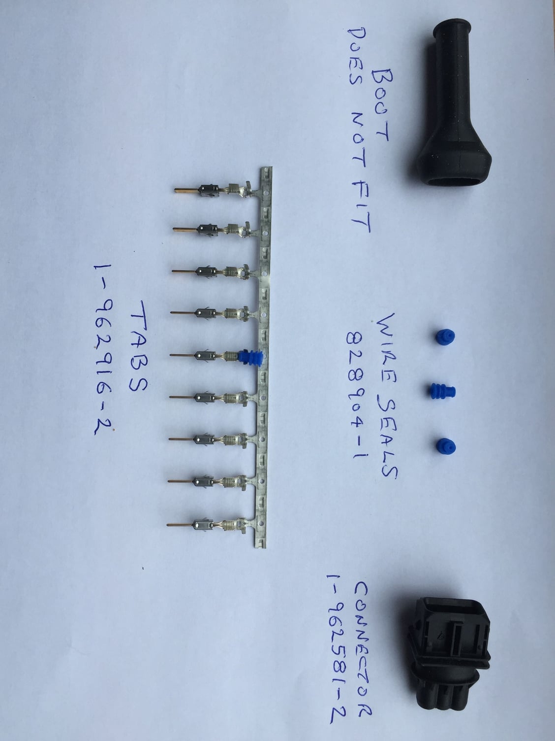
Parts list. Boot not available.
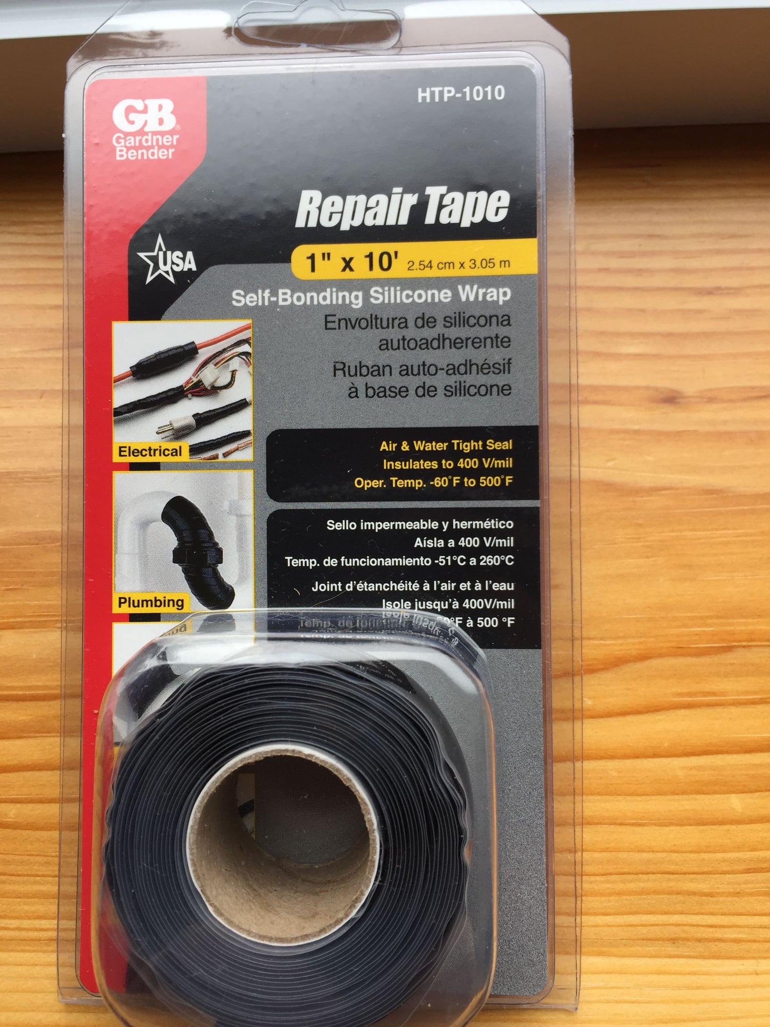
Self-sealing tape

Old connector removed. Tabs ready to be cut off.
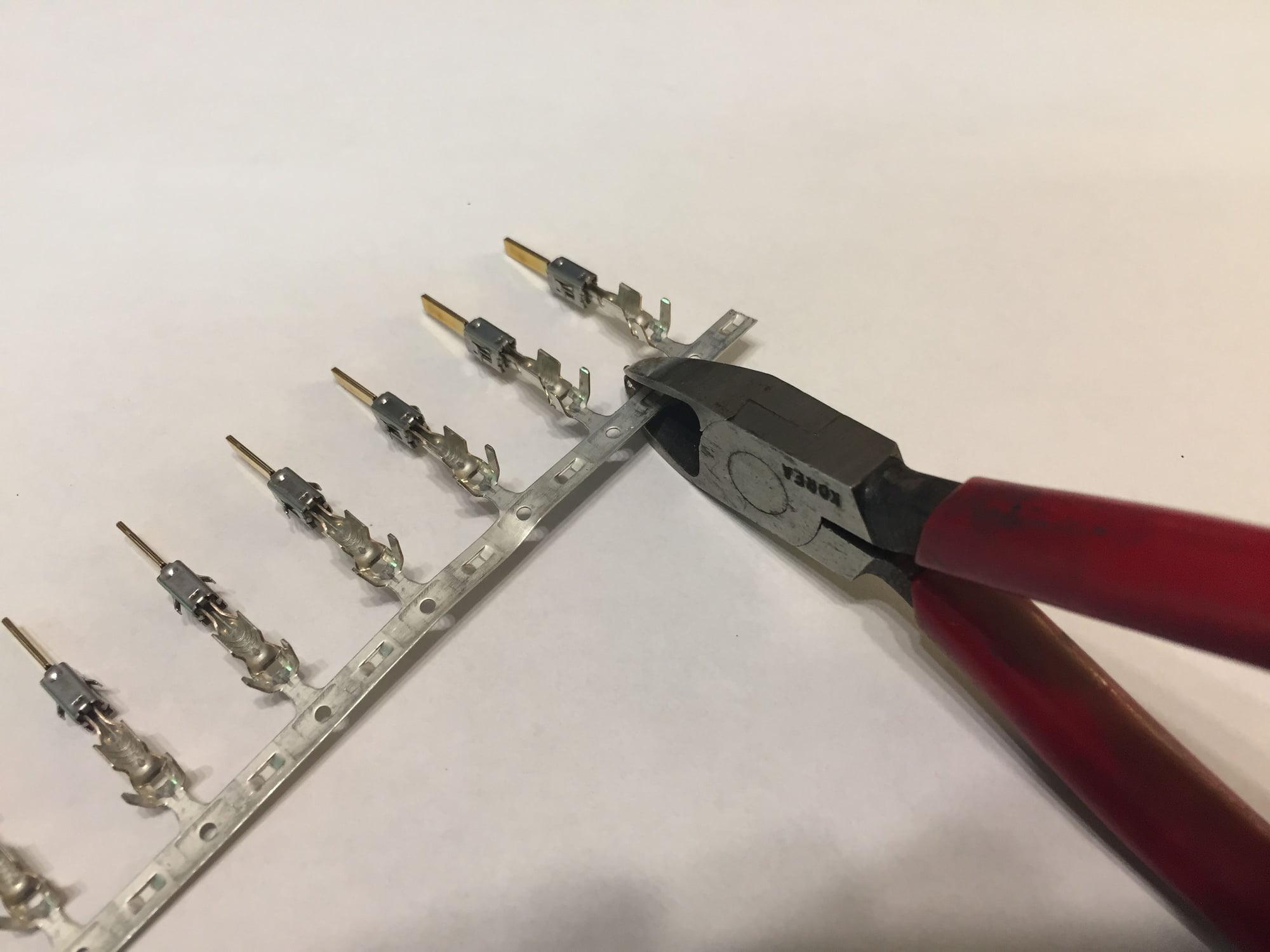
Cut new tabs from band of tabs.
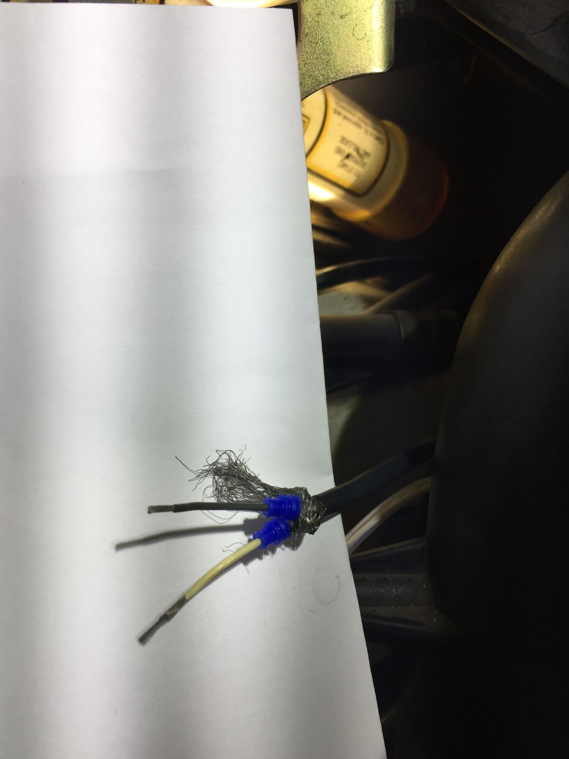
Shield has been unbraided
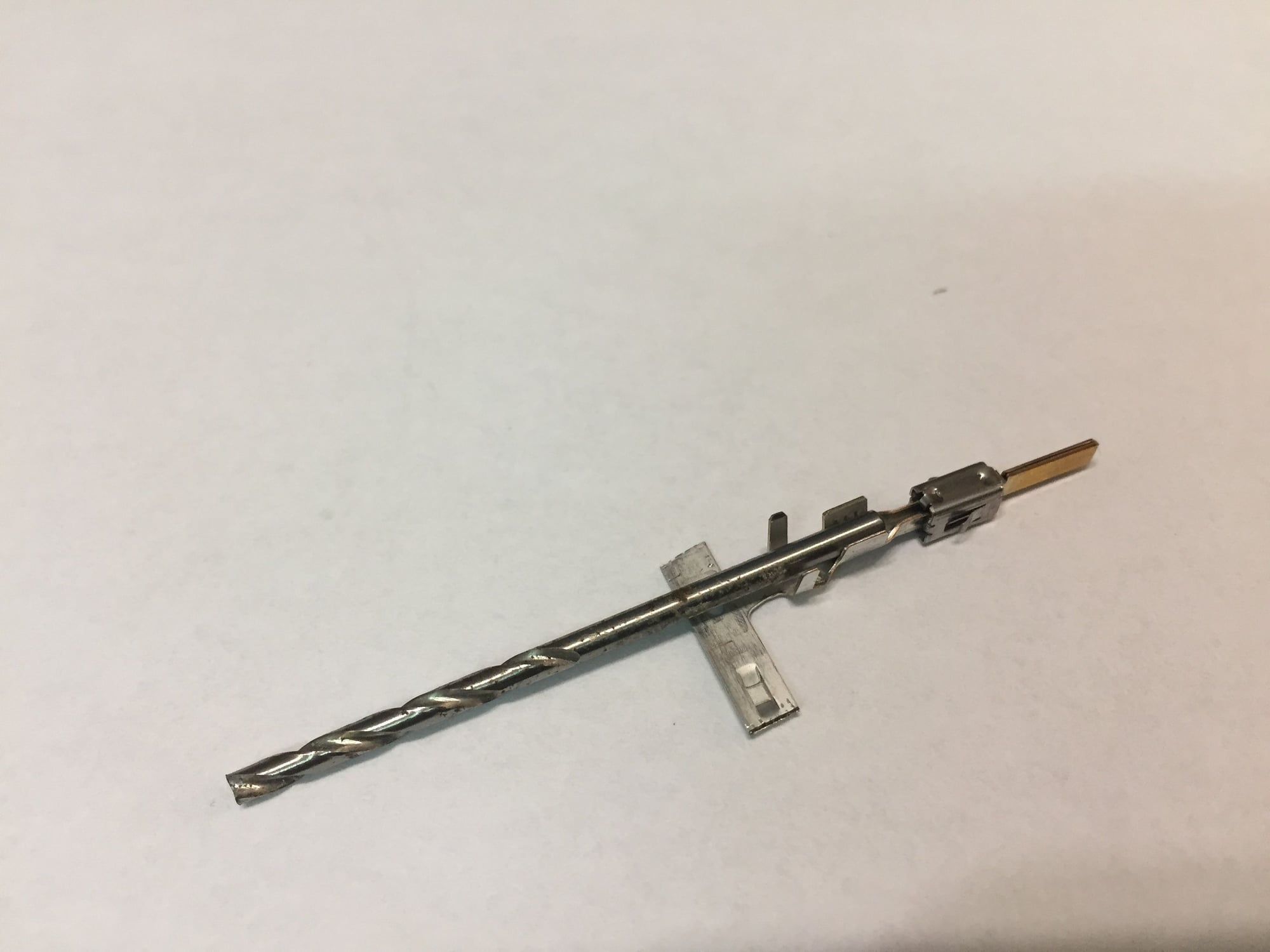
Drill bit for pre-forming tab to accept wire.
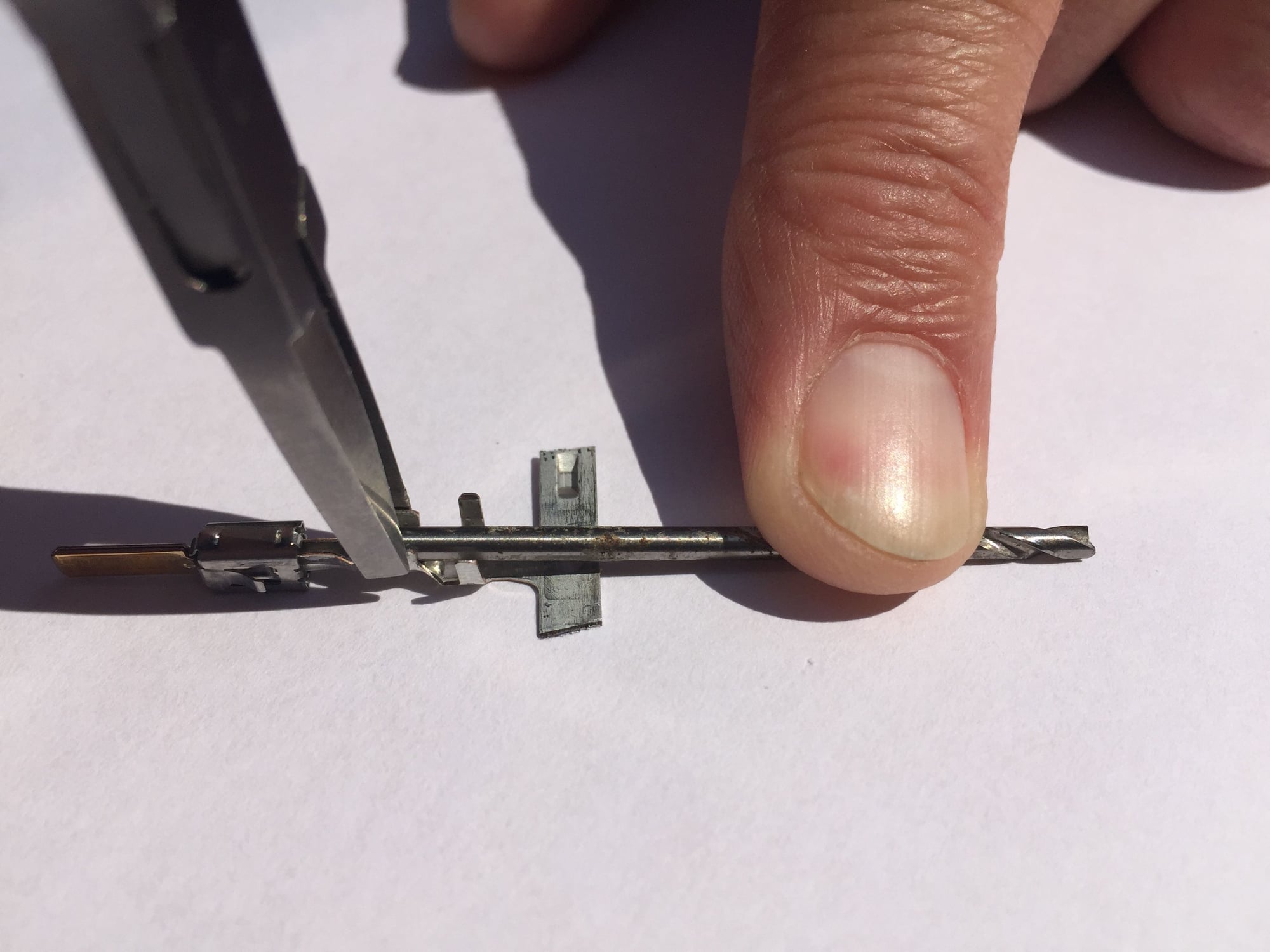
Pre-forming tab
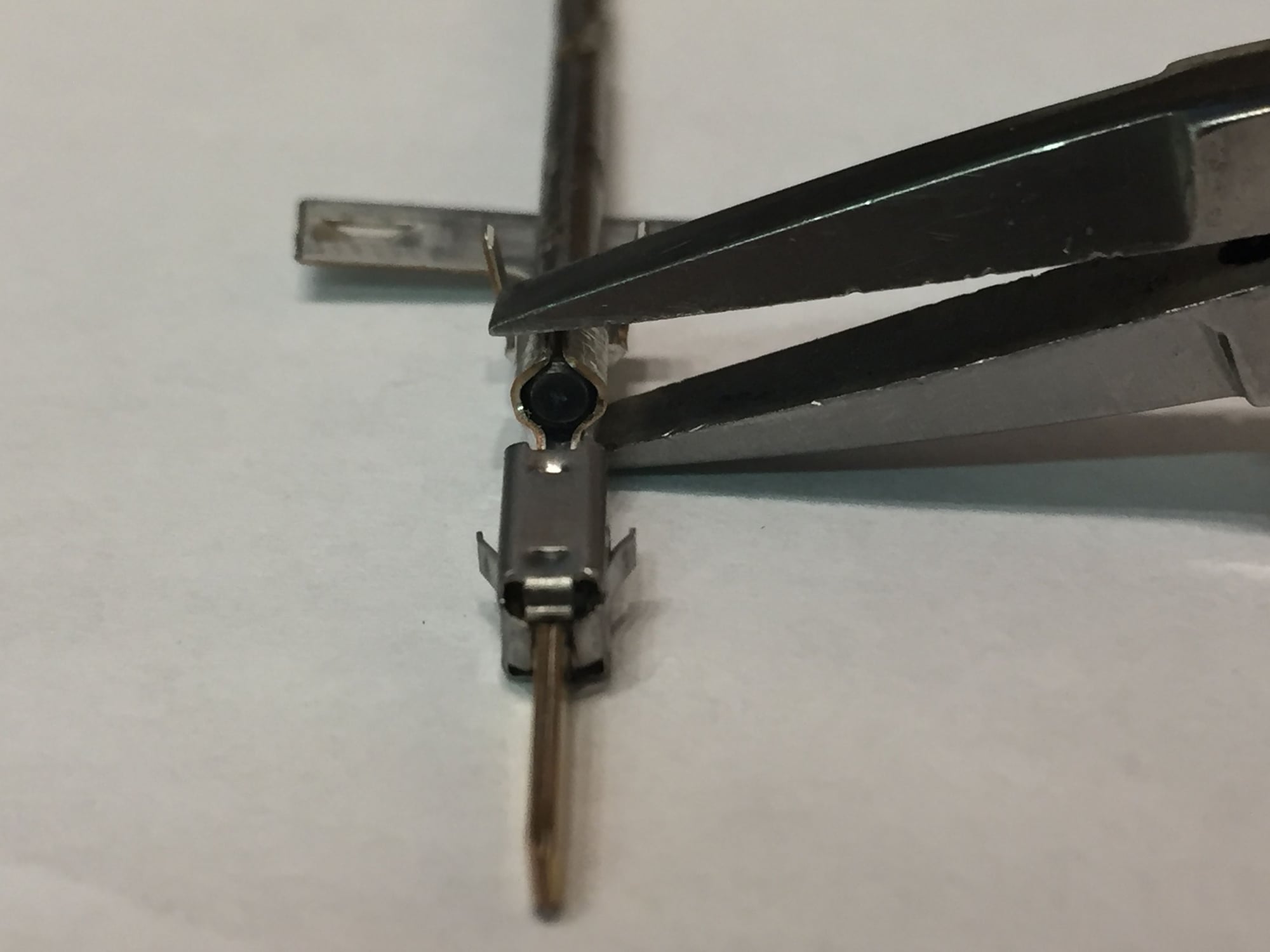
Done with large drill bit, ready for small bit.
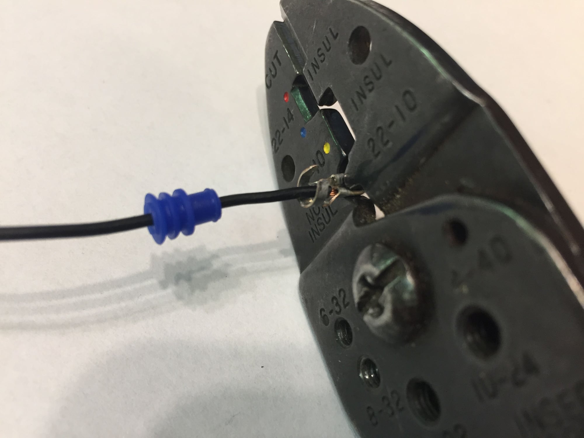
Wire crimped and ready for solder.
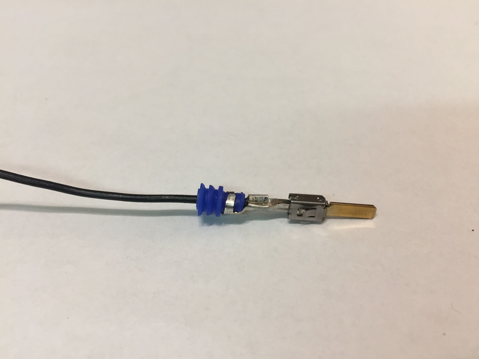
Wire seal crimped to tab.
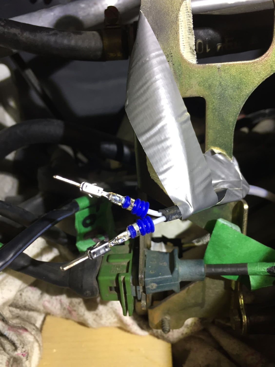
Ready for connector. Duct tape helps hold wires from moving.
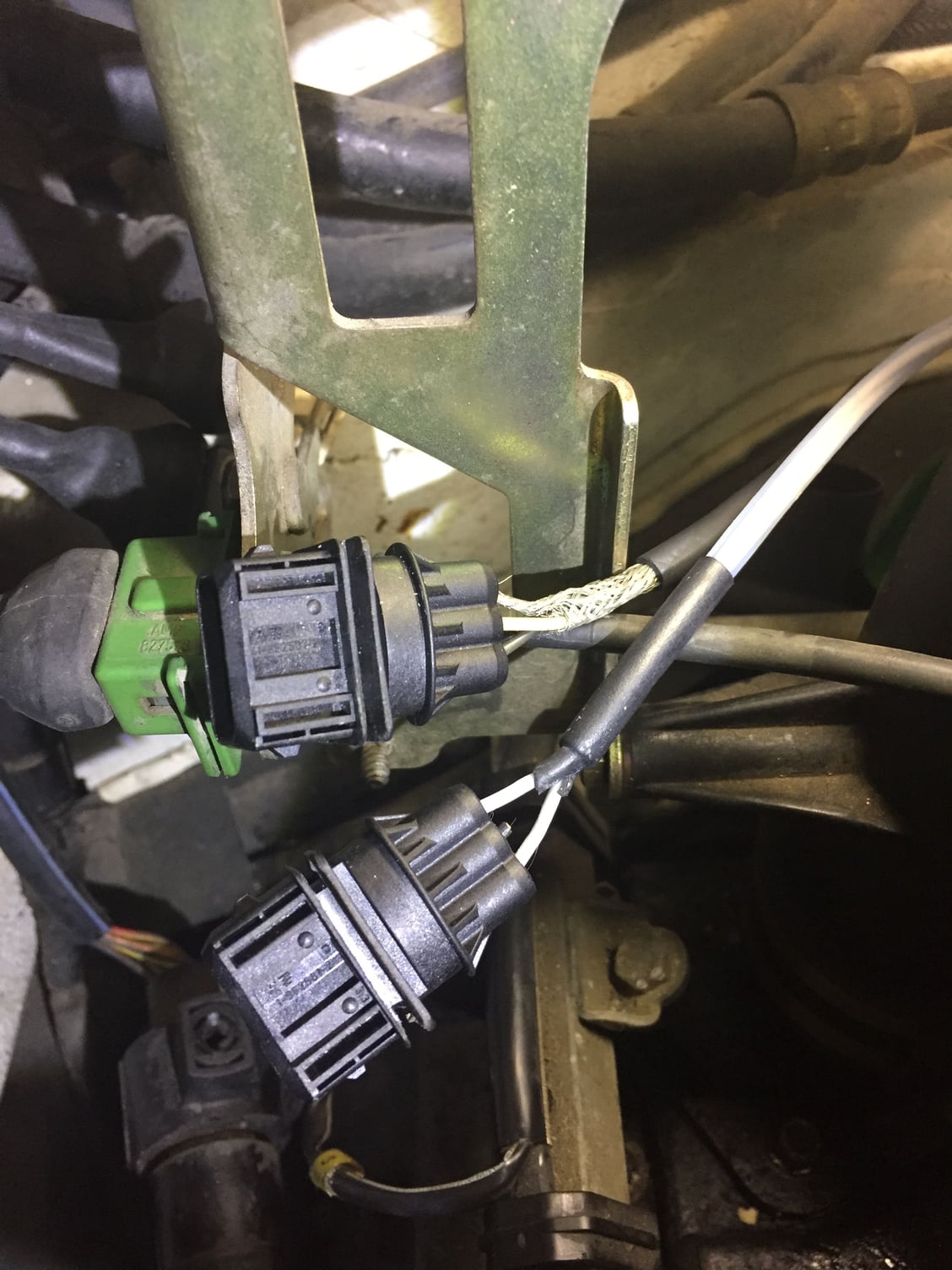
Ready for self-sealing tape.
#34
Pro
Thread Starter
Pete if your connector is like mine, you cannot remove the pins because they are molded in. You have to either cut the connector off completely or crush the connector (it will be very brittle) and then clip the pins off. Crushing and clipping saves a bit of wire and there is not a lot to spare so I crushed mine.
#35
Thanks for that info!
I just wanted to link this post because the information is relevant concerning connector availability.
https://rennlist.com/forums/964-foru...onnectors.html
I just wanted to link this post because the information is relevant concerning connector availability.
https://rennlist.com/forums/964-foru...onnectors.html
#36
Pro
Thread Starter
Here is another link that should be checked out. I just placed my order as this complete kit of both male and female connectors seems like a steal of a deal. Credit to -Nick for finding this one.

