When you click on links to various merchants on this site and make a purchase, this can result in this site earning a commission. Affiliate programs and affiliations include, but are not limited to, the eBay Partner Network.
Help please - vacuum connections after engine drop
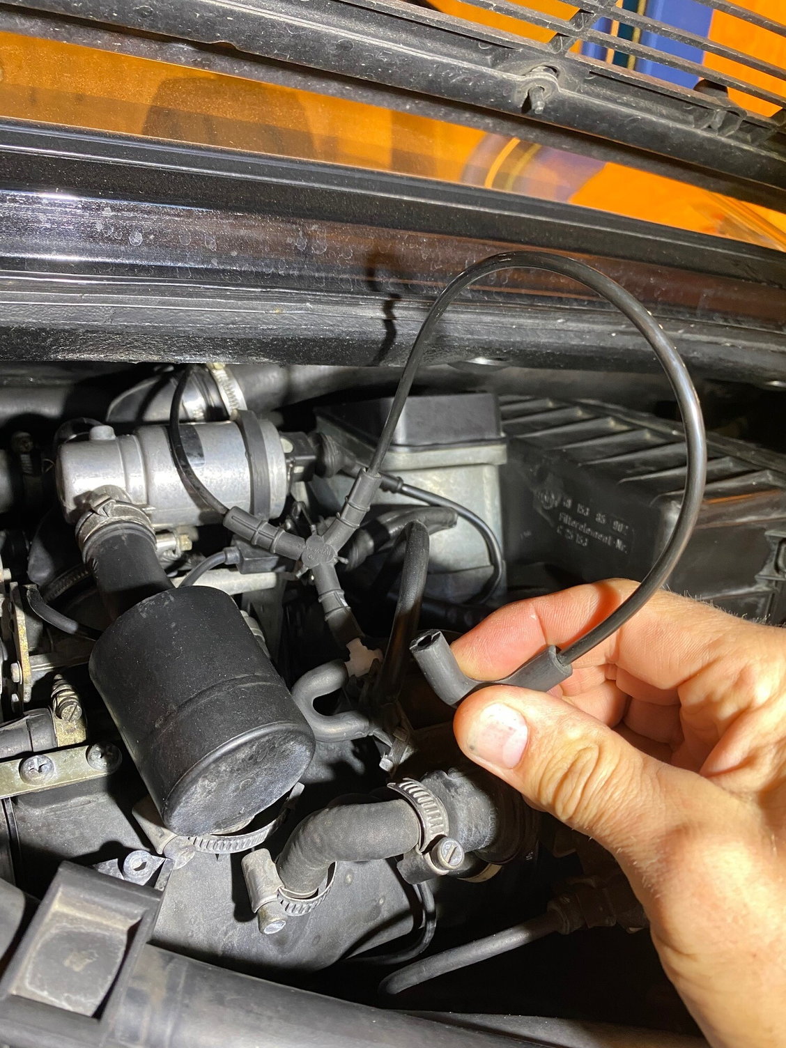
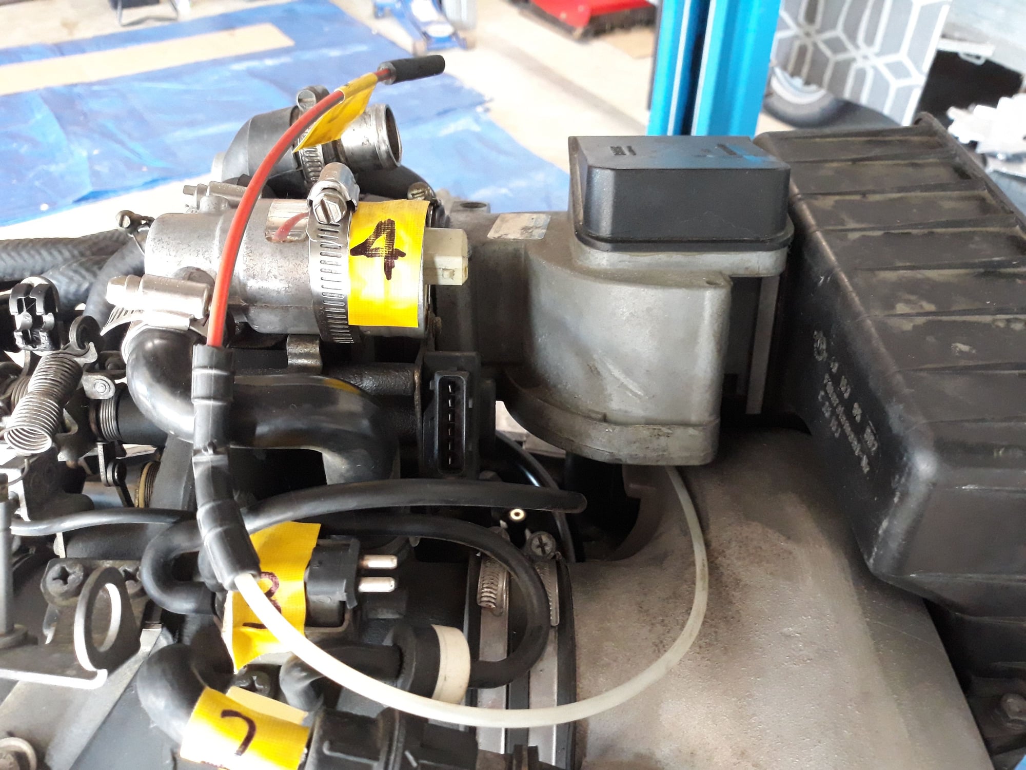
Just did a tip to manual conversion today (see other thread). Two vacuum lines are left and I cant find where to join them!
The first comes from the three-linkage right on top of the intake. The second comes out of the blower motor tube - it has a joiner on the end that looks quite specific. Searched and looked through the PEF but cant find it....thanks in advance.
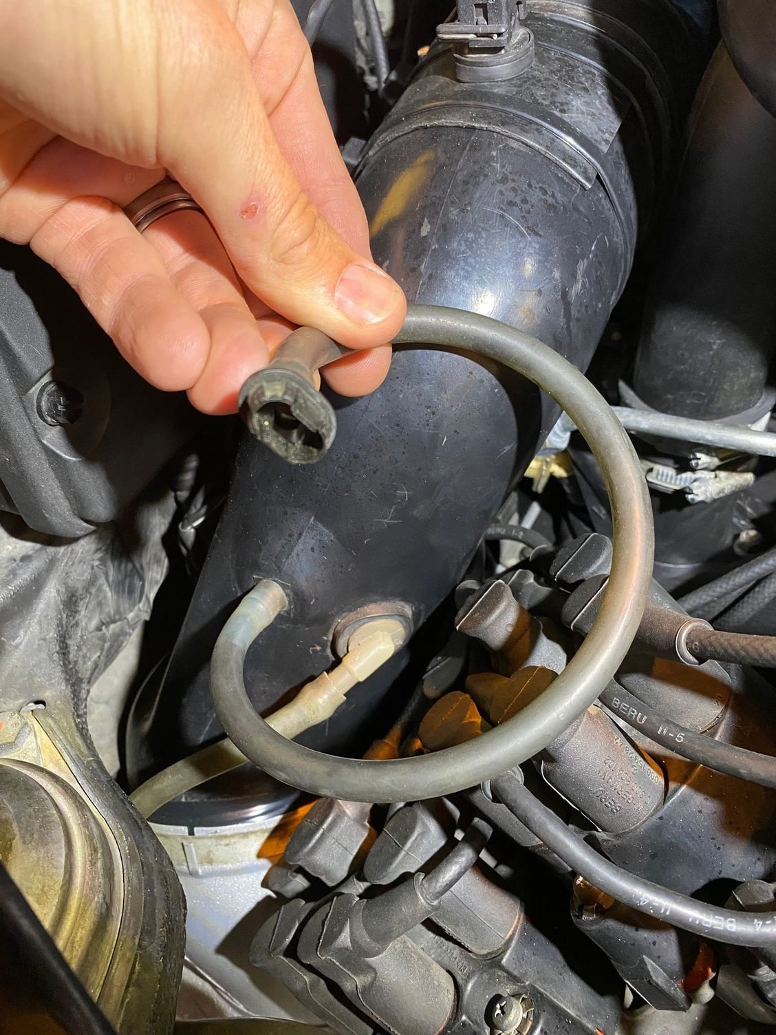
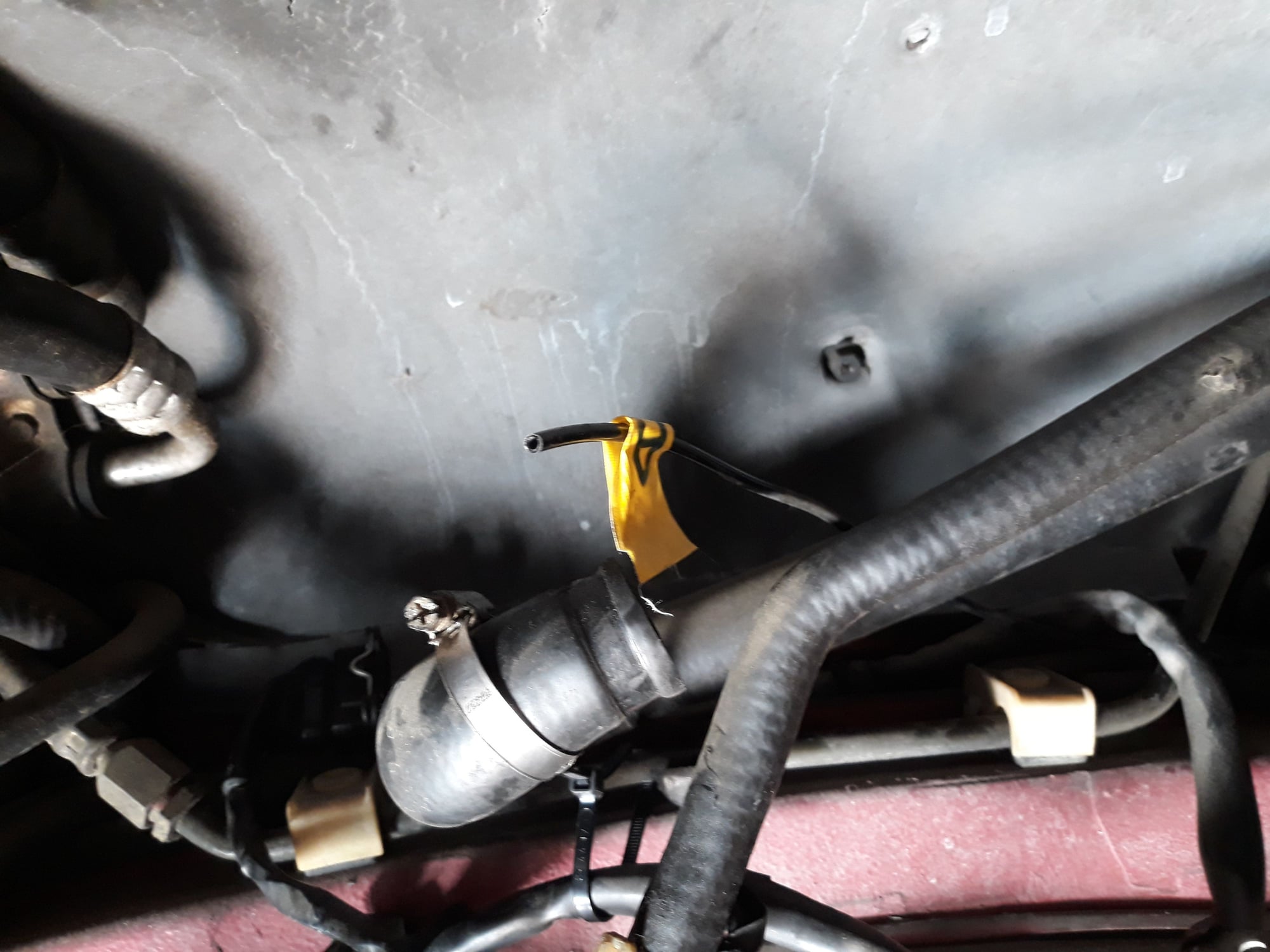
The bottom pic is one that connects to your distributor. The top pic is one which you have a y connector likely to a vacuum solenoid or vacuum actuator depending on your setup. The vacuum system is actually a simple system. Follow the lines until they end at the valve where the motor creates vacuum or the other end which is through a solenoid and eventually to a actuator where it terminates.
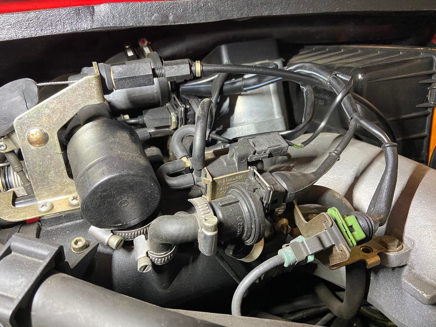
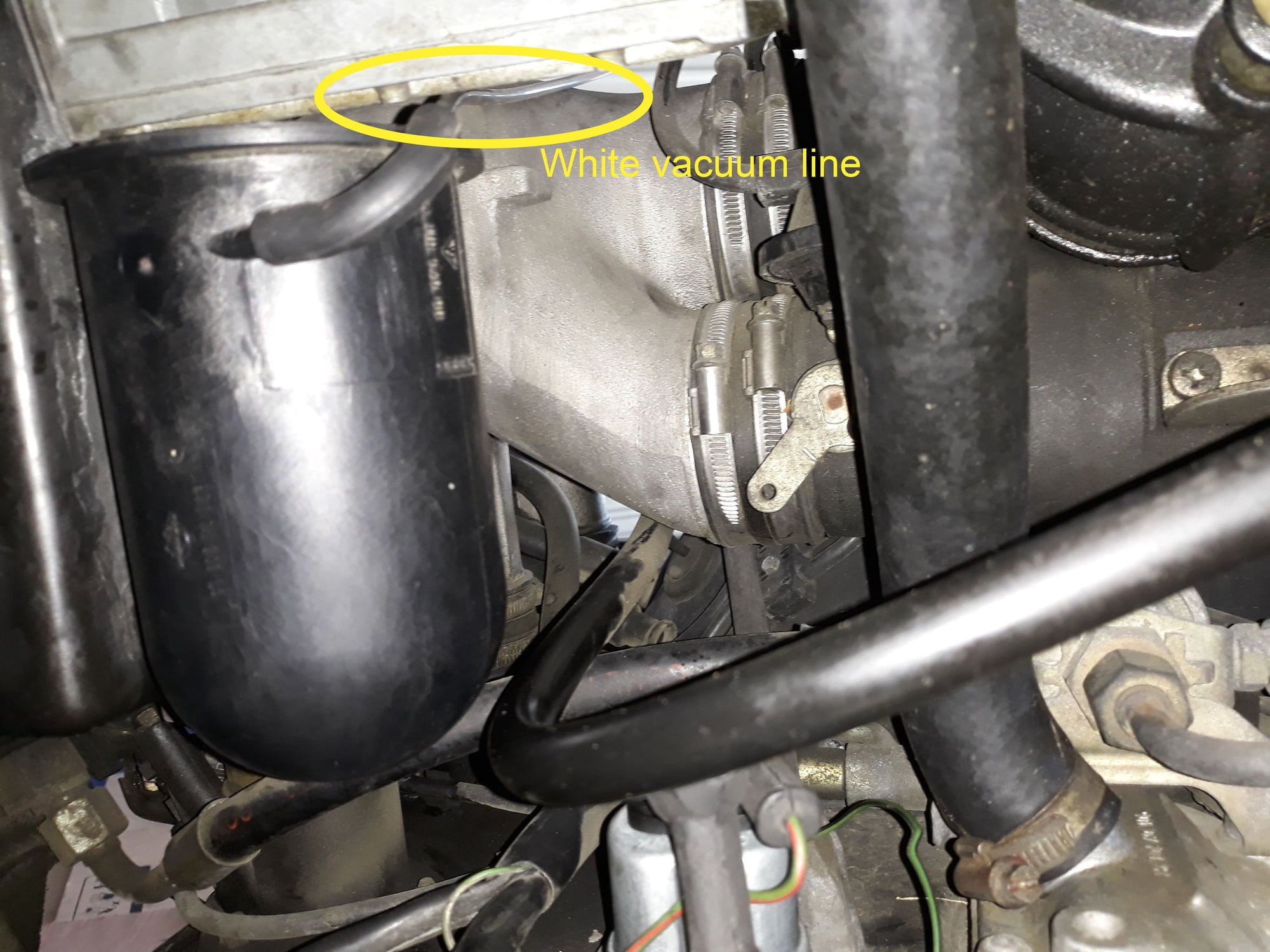
The first pic shows my T junction with the white line going to the carbon canister behind the airbox (see pic 2).
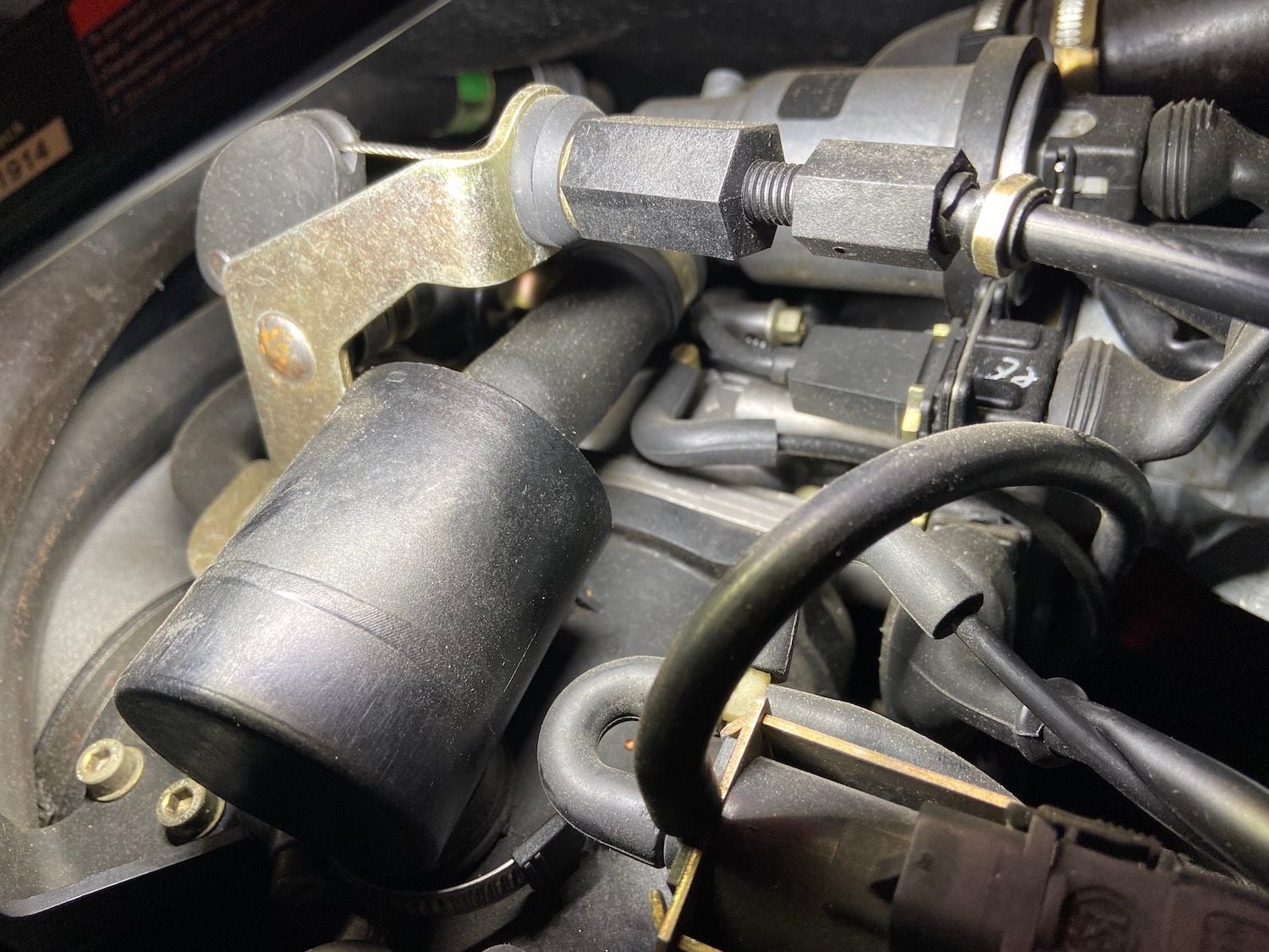
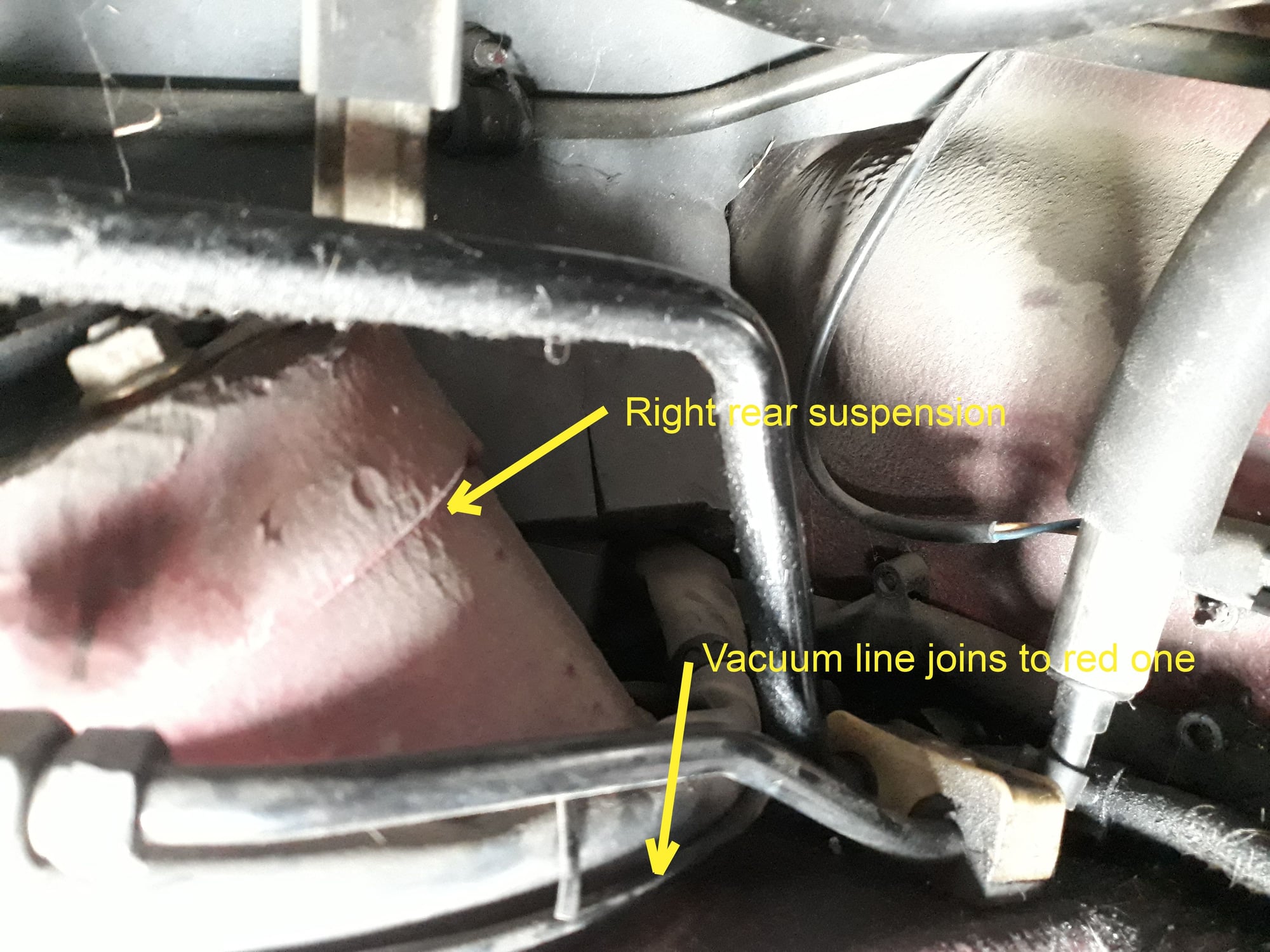
The red vacuum line (pic 3 with the upside down A) goes off behind the engine up against the insulation and then to the RH rear suspension (pic 4).
Where it actually goes i have no idea. Is this vacuum line setup unique to ROW cars? The white vacuum line goes to the carbon canister behind the airbox. The red one joins up to a black line up against the engine insulation. Back of the airbox. Red vacuum line joins this line (the upside down A) up against the engine insulation. It is routed around the suspension tower and i have no idea where it goes........yet.
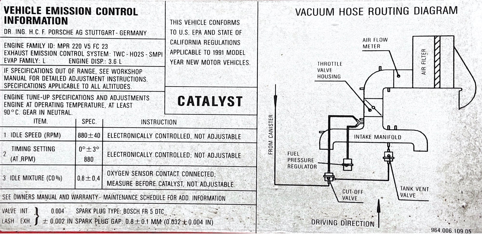
I completely forgot about that diagram. Here is the one on my 1991 C2 Tip for reference. Looks the same. This is a USA car compliant with California emissions. This will be helpful for my intake rebuild in progress.

 05-17-2020, 03:15 AM