When you click on links to various merchants on this site and make a purchase, this can result in this site earning a commission. Affiliate programs and affiliations include, but are not limited to, the eBay Partner Network.
Using a friend's Rennlist 964/993 scan tool, my 964 C2 is throwing a 34 - Hall sensor error code, no light on the dash though. I've gone through all the post here and on Pelican but still have a couple of questions.
I've just done a full rebuild on the engine, bottom and top, including new spar plugs, spark plug wires, coils and rebuilt distributor (Steve Weiner @ Rennsport).
Here is what we measured:
- we have a good ground, 5V and 12V at the distributor connector engine off, we removed the boot and everything looks fine in there.
- we have continuity from that connector to the 55-pin DME connector (pins 8, 24 and 31)
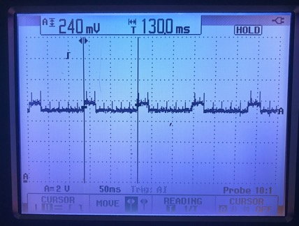
- engine idling, we used an oscilloscope to measure the signal emitted from the hall sensor at the distributor and at the DME and obtain the same graph shown below:
Engine running at around 900rpm, diff between 2 signals is 130ms
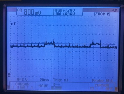
Engine running at 900rpm, base voltage at around 7V and delta is around 800mV
Anybody can comment on the readings? The 800mV seems weird to me but I do not know what I should expect here...
Thank you!
PS: Lorenfb if you're around, I'd love to get your input on this, after reading threads after threads it seems that you're the guy that knows stuff about this
Car seems to run fine, but I've read somewhere here or on Pelican that a hall sensor issue will basically retard the timing by 6 degrees, that you can not really feel it driving the car unless you're drag racing another 964 next to you... After all the money and time I've put in the rebuild, if I'm losing 6 degrees of timing I wanna know about it!
Using a friend's Rennlist 964/993 scan tool, my 964 C2 is throwing a 34 - Hall sensor error code, no light on the dash though. I've gone through all the post here and on Pelican but still have a couple of questions.
I've just done a full rebuild on the engine, bottom and top, including new spar plugs, spark plug wires, coils and rebuilt distributor (Steve Weiner @ Rennsport).
Here is what we measured:
- we have a good ground, 5V and 12V at the distributor connector engine off, we removed the boot and everything looks fine in there.
- we have continuity from that connector to the 55-pin DME connector (pins 8, 24 and 31)
- engine idling, we used an oscilloscope to measure the signal emitted from the hall sensor at the distributor and at the DME and obtain the same graph shown below:
Engine running at around 900rpm, diff between 2 signals is 130ms
Engine running at 900rpm, base voltage at around 7V and delta is around 800mV
Anybody can comment on the readings? The 800mV seems weird to me but I do not know what I should expect here...
Thank you!
PS: Lorenfb if you're around, I'd love to get your input on this, after reading threads after threads it seems that you're the guy that knows stuff about this
There appears to be a poor/weak ground as the Hall device is producing a signal but;
1. There's a poor connection to the actual ground via pin 24, or
2. The Hall device is weak and fails to fully 'pull' to ground, or
3. The pin 8 of the ECM is possibly shorted to another wire preventing the Hall device
from fully 'pulling' to ground.
Loren, thanks for the super quick reply. So if I understand the signal should be 0 or some voltage correct? Does the 7V seem correct to you?
I will look into the ground sometime this week and post what I find!
Loren, thanks for the super quick reply. So if I understand the signal should be 0 or some voltage correct? Does the 7V seem correct to you?
I will look into the ground sometime this week and post what I find!
The signal should go from about 1.0 volts to about 8 volts and have the same form as the present
800mv peak-to-peak signal. Your signal fails to reach the lower value (1.0 volts).
Note: The ECM input (pin 8) shouldn't require more than about 10ma to 'pull' to ground (~ 1.0 volts)
from the Hall device.
I'm the helper friend. Thanks all for your help :-)
Loren, can we check the sensor with the distributor out of the car to rule out harness / ground issues ?
The idea would be to rotate the dizzy with a power drill and checking the signal.
Electrically, what would we need to provide to the dizzy to do this ?
Can the sensor be misaligned so that the field would only be partially blocked ?
-Guillaume
Yes, the Hall device can be checked with dist. out of the engine:
1. The pin 31 (brn wire of sensor) of the ECM connects to 12 volts.
2. The shield goes to ground.
3. The pin 8 (wh wire of sensor) of the ECM needs a load resistor (~ 2K - 5K) to 12 volts.
The dist. shaft can be turned by hand. The white wire lead should be grounded when
the magnet aligns with the Hall sensor and 12 volts at other positions.
Quick update: testing the distributor on the bench tells us the hall sensor is fine. Using an old battery, we get 7-8V and 60mV.
Putting the distributor back in the car and measuring directly at the DME gives us same result (with engine off, key on the on position).
So we must have something polluting the ground when engine is running.
Our idea is too first check with oscilloscope at DME again with engine running to make sure we're getting the same signal as we had a few days ago. Then remove relays one by one and try to determine what is causing the issue.
Any comments on that idea or other ideas are welcome!!
So some more update tonight: before going any further we decided to measure the signal at the DME again with engine running, just to be sure.
This time instead of having 8V with a drop of 800mV we had a clear signal from 0V to 5V. Signal looks really clean but it is not 1V to 8V... Loren, would 5V be an issue here?
We checked the code with the scan tool again and the hall sensor code is gone...
Things to fix themselves but we're out of ideas... We're going to check the codes regularly but it looks like the car is really running fine tonight!
Steven, I wouldn't say false, when we measured the signal the first time (see graph above) it was definitely wrong (not grounding). Yesterday the signal was identical in shape but was grounding properly. So there is something we did, maybe by disconnecting some plugs, that "fixed" it.
I don't like this kind of "fix" because for me the issue can come back anytime. I'll keep an eye on it.
Anyway, to answer your question, I've got 2 new hall sensor coming from Germany that I had ordered when my friend Guillaume and I were convinced it was the hall sensor.
I ordered them from here: http://www.hallsensors.de/Hall-Vane.htm
CYHME56C is the one you want for the 964
In July 2017 paid 15.38 euros plus 9.69 euros in taxes and 15 euros for shipping to here in Texas.

 07-24-2017, 02:03 AM