When you click on links to various merchants on this site and make a purchase, this can result in this site earning a commission. Affiliate programs and affiliations include, but are not limited to, the eBay Partner Network.
I have some odd running issues including an intermittent no-start, similar to the DME relay issue (except it's not the relay). I get one initial tach bounce during these no-start episodes, and nothing after that.
I checked out the crank sensors with a digital scope. Do these signals look ok? The things that concerned me were:
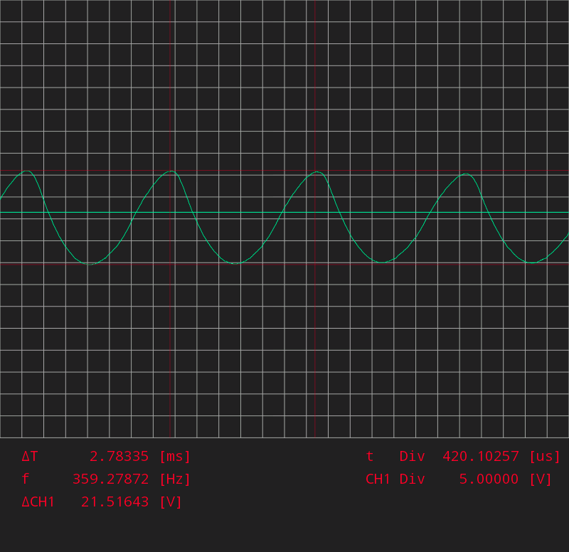
1. Speed sensor signal is over 20v peak to peak. I was expecting around 2v. Is this ok?
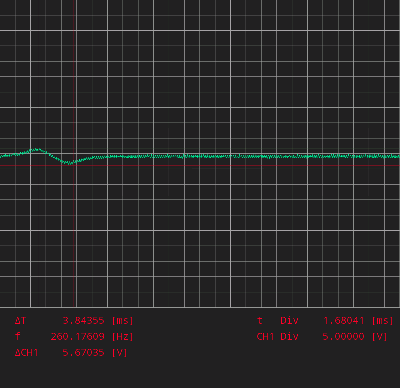
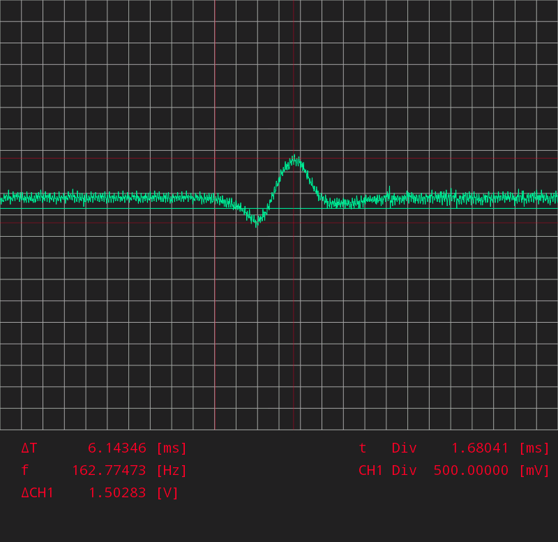
2. The reference sensor signal is very noisy. Is that normal/ok? I tried probing it again at the sensor connector (the first one below was taken at the DME connector). The noise was still there, but the signal had a few other differences: it seems to be inverted and the peak to peak voltage is down from 5.6 to 1.5, which is well below what's needed according to the factory test plan. I presume the inversion is just because of the way I hooked up the probe...but why would the voltage be lower?
Here's the speed sensor signal at the DME connector:
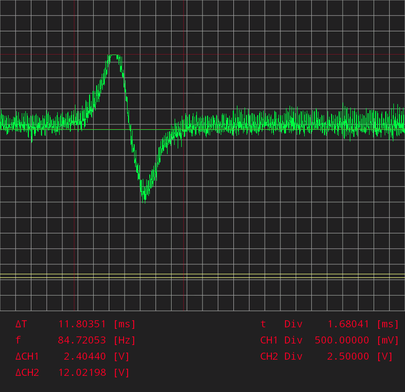
The reference sensor signal at the DME connector:
And the reference sensor again, this time at the sensor plug itself. I used the scope's amplifier to make this clearer, which is why it looks bigger than the one I took at the DME connector:
How familiar are you with the o-scope you are using, and the probe and trigger settings? It doesn't seem set up right...? What RPM was that -- or is the car not running and that just the view with the motor cranking on the starter motor? I can't reconcile the frequencies to anything you'd expect to see with the motor running, nor do the speed and ref sensor frequencies reconcile to each other...
How familiar are you with the o-scope you are using, and the probe and trigger settings? It doesn't seem set up right...? What RPM was that -- or is the car not running and that just the view with the motor cranking on the starter motor? I can't reconcile the frequencies to anything you'd expect to see with the motor running, nor do the speed and ref sensor frequencies reconcile to each other...
Thanks...that's just cranking, not running. About 150rpm based on the speed sensor signal. I assumed that's how they're supposed to be tested, since you have to disconnect the plug to get access, and also they must be capable of putting out the right signal when cranking, or else it wouldn't start, right?
I don't have much experience with scopes, but I understand the basics. I'm going to get hold of a good function generator so I can play around with it and get the hang of it. The trigger on this scope just centres the image where the signal crosses the trigger...for the speed signal I pretty much left the time scale wherever it happened to be. It also has a single-shot mode. You can configure it for rising or falling edge also (I have it set up to trigger on the rising edge).
I think the reason the images don't reconcile with each other is that the time/div is different on each. These were separate tests. For the crank sensor I set it to the slowest possible because it was hard to see the signal otherwise. The speed sensor signal was clean and easy to acquire, but he ref sensor seemed very erratic and hard to capture anything repetitive.
The probe is a standard x10.
This is the scope I'm using - it uses an Android device as the display and user interface. I had to have something portable and most of the portable ones out there are either junk, very expensive and/or have horrible user interfaces.
I thought I had some screen shots of the speed and ref sensors but can't seem to find them. Will keep looking, but they should look pretty close to the pictures in the FSM. Re the x10, on my pc-based o-scope, you have to tell the software when the probes are set that way -- otherwise you get 10 times the actual voltage....
I thought I had some screen shots of the speed and ref sensors but can't seem to find them. Will keep looking, but they should look pretty close to the pictures in the FSM. Re the x10, on my pc-based o-scope, you have to tell the software when the probes are set that way -- otherwise you get 10 times the actual voltage....
I wondered about the x10 probes too, but the app has a manual probe calibration option, and they also store calibration data for each specific unit before they ship it. You just press a button in the app, enter the unit's serial number, and it fetches the calibration from their website. I did this, then put it in DC mode and compared it to my mulitmeter, checking the voltage of a battery pack I had lying around. It was spot on. The hardware also has the option to amplify the signal being measured (controlled via the app) but I think it takes that into account when showing the voltage values on the screen. This is the kind of thing I need that function generator for, to make sure I know exactly what it's doing.
According to the factory test spec, the reference signal should be more than 2.5v from baseline to peak - and it is speed dependent (faster = higher voltage).
The speed sensor will yield higher voltage (and is usually measured peak-to-peak). It has to be above a certain threshold for the DME to read it - I think that threshold is also 2.5v. In another thread, Perry says he's getting -12v to +12v (delta over 20v).
I would think that the gap between the sensor and the teeth / set screw play a big role in voltage differences, too.
Yeah test plan says 2v positive peak for the reference sensor, 2.5 peak to peak for the speed sensor.
For the reference sensor, I had 5.6v total when I checked it at the DME connector, but only 1.5v when I checked it at the sensor connector. Then there's the noise. It was there in both tests. The fact that it's not there in the other sensor suggests it's not the scope, or me doing something wrong. From reading other posts and looking at the DME pinout, the speed sensor is shielded with the O2 sensor to pin 23, but the ref sensor shield is is at pin 5, which is also a major ground point. So maybe there is a problem with that ground causing the noise.
I found a scope image of what I think are the same 2 sensors on a BMW site. His reference sensor output is free of noise and looks very like the one in our test plan. I noticed his speed sensor signal also has the same slightly off-sine shape that mine has.
Are your measuring the speed sensor while it is connected to the DME or not?
If it is not connected to the DME then you are reading the sensor's open circuit voltage and it will not be accurate. You need to have a load across it's output, which is what the DME's internal electronics is.
Are your measuring the speed sensor while it is connected to the DME or not?
If it is not connected to the DME then you are reading the sensor's open circuit voltage and it will not be accurate. You need to have a load across it's output, which is what the DME's internal electronics is.
No neither sensor was connected to the DME for any of the above tests. I couldn't connect the sensors to both the DME and the scope at the same time.
Back-probe the speed/ref-sensor terminals at the DME-connector itself. This will also test the wiring-connector and wiring in between as well.
I took the plug cover off and tried to plug it back in but it was tricky without putting a lot of pressure on the wires. I didn't want to damage anything so I thought I would get some wires that will be a tight fit into the back of the terminals, and run them down to where the harness comes into the connector, then put the cover back on. Then I can plug it in and attach my probes. Is that a good way to do it?
Push a small sewing pin through the wire. It will touch the inner conductor and allow you to attach the scope probes, or;
Buy a pair of alligator clips that have an insulation piercing pin. You can make up a small adapter cable with the alligator clip on one end and any type of terminal to attach your scope probe to.
Thanks for the tip. I see now that there are various piercing probes and clips out there for this. I didn't know that.
I took the plug cover off and tried to plug it back in but it was tricky without putting a lot of pressure on the wires. I didn't want to damage anything so I thought I would get some wires that will be a tight fit into the back of the terminals, and run them down to where the harness comes into the connector, then put the cover back on. Then I can plug it in and attach my probes. Is that a good way to do it?
If you take the cover off the DME you can clip probes on the metal pins off the main connector -- the ones that solder into the DME board to mount the main connector. You can also make a patch cable to plug in between the sensor and the harness, with a spot to probe.
OK so I did a test on the reference sensor with the engine running. The only way I could do it was the way I described before, i.e take the cover off, insert test wires, put cover back on. The sensor wires are all inside a thicker insulation so I couldn't really stick pins into them.
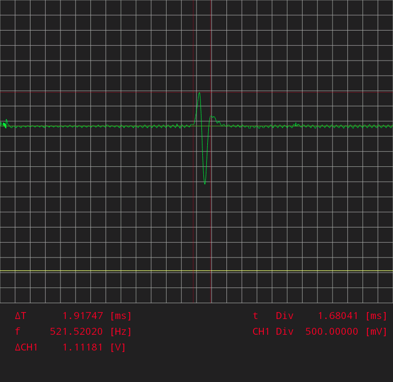
I was surprised to find that the noise more or less disappears when I test it this way. But, the voltage is way lower. The positive spike is only around 1.2v at idle. When I was testing with the open connector, it was much higher than that, even at cranking speeds. With the engine running, I have to get to about 1500rpm to make it come up to the 2v called for in the test plan.
Here's what it looks like at idle:
So it looks like I need to check/adjust the sensor gap.
Still, I'm very curious about the noise that I get on the signal when it's disconnected. I presume the reason it goes away when connected because the shield is grounded. But why doesn't the speed sensor have any noise when disconnected? Should I be concerned about it? I took a closer look did a few tests. Firstly, here's a clearer picture with the correct polarity (unlike the one I posted before):
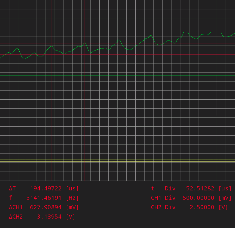
The noise is over half a volt while the signal is around 5v peak to peak. I zoomed in so I could measure the noise - it's around 5khz:
I thought of the alternator as a possible source of ac noise, so I pulled the belt. No difference.

 11-16-2014, 08:29 PM