
Refresh951's Hybrid Ultra Stroker Build

 07-03-2013, 01:40 PM
#767

I don't need (or... gasp! ... want) the extra power from the stroker build BUT the non-interference design + low cost makes it tough for me NOT to consider when I pull my car apart this winter to re-ring it (170k+ means I'm sure it's due...)
07-03-2013, 01:42 PM
#768
The factory 944/951 design is an "interference" one. Which is why, usually, when the timing belt breaks, you need to (at a minimum) pull the head and replace bent valves. The beauty of going to a non-interference design is exactly what Rogue described and Sid experienced... TB breaks, the car just stops. Slap a new belt on, and off you go.
07-03-2013, 03:53 PM
#770
Race Car
Put the pistons at TDC
Put some clay on the top of tge piston around valve reliefs
and then bolt s head down using a light valve spring and open the valves to whatever your valve lift is.
Pull the head off and measure how thick the clay is at its thinnest point.
I like to have .100-.150"
If you can't open the valve to full lift or have minimal clearance, it will hit the valves if the belt breaks.
07-03-2013, 05:53 PM
#771
Three Wheelin'
Thanks Sid! As soon as i get all of it in i'll try that, do i have to torque the head as well or is it good enough to just put it on and bolt it down a bit?
07-03-2013, 06:06 PM
#772
Rennlist Member
Thread Starter
 The HS 2.85L is a GREAT motor. You could build one with no need for expensive 3L parts and with the turbo you have could quite easily get 400 rwhp and have a non-interference design.
07-03-2013, 08:25 PM
The HS 2.85L is a GREAT motor. You could build one with no need for expensive 3L parts and with the turbo you have could quite easily get 400 rwhp and have a non-interference design.
07-03-2013, 08:25 PM
#773
Rennlist Member
Thread Starter
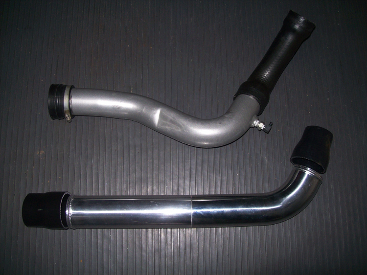
Side by side comparison of the IC inlet pipes. I pretty much used SFR pipes as a guide. Tim's stuff was pretty awesome really. His designs were simple and efficient. It really is a shame he is not doing much with our cars these days.
At 750 cfm (around 500 flywheel hp), my calculations show this redesigned pipe to be a 3 psi pressure drop improvement. Therefore the turbo has to generate 3 psi less boost to produce the same intake pressure (at 750 cfm). This results in a significant improvement in heat generation not to mention more peak boost potential!
At 750 cfm (around 500 flywheel hp), my calculations show this redesigned pipe to be a 3 psi pressure drop improvement. Therefore the turbo has to generate 3 psi less boost to produce the same intake pressure (at 750 cfm). This results in a significant improvement in heat generation not to mention more peak boost potential!
 07-03-2013, 10:50 PM
#776
Rennlist Member
Thread Starter
07-03-2013, 11:11 PM
#777
Rennlist Member
07-03-2013, 11:18 PM
#778
Drifting
Join Date: Aug 2009
Location: Bangkok, Thailand, Milpitas, CA & Weeki Wachee, FL
Posts: 2,239
Likes: 0
Received 2 Likes
on
1 Post
I would use a metal NPT to Pushlok tubing adaptor if it were mine. Make things simple and tidy. I will try to find a link.
In my phone so this is the best I can do:
http://www.smcusa.com/top-navigation/cad-models.aspx/21987
In my phone so this is the best I can do:
http://www.smcusa.com/top-navigation/cad-models.aspx/21987
07-04-2013, 05:13 PM
#779
Rennlist Member
I would use a metal NPT to Pushlok tubing adaptor if it were mine. Make things simple and tidy. I will try to find a link.
In my phone so this is the best I can do:
http://www.smcusa.com/top-navigation...els.aspx/21987
In my phone so this is the best I can do:
http://www.smcusa.com/top-navigation...els.aspx/21987
MM
07-04-2013, 06:52 PM
#780
Rennlist Member
Side by side comparison of the IC inlet pipes. I pretty much used SFR pipes as a guide. Tim's stuff was pretty awesome really. His designs were simple and efficient. It really is a shame he is not doing much with our cars these days.
At 750 cfm (around 500 flywheel hp), my calculations show this redesigned pipe to be a 3 psi pressure drop improvement. Therefore the turbo has to generate 3 psi less boost to produce the same intake pressure (at 750 cfm). This results in a significant improvement in heat generation not to mention more peak boost potential!
At 750 cfm (around 500 flywheel hp), my calculations show this redesigned pipe to be a 3 psi pressure drop improvement. Therefore the turbo has to generate 3 psi less boost to produce the same intake pressure (at 750 cfm). This results in a significant improvement in heat generation not to mention more peak boost potential!