

Please review my autothority MAF wiring (photo inside)
 06-17-2008, 06:06 PM
#1
Racer
Thread Starter
Join Date: Jun 2005
Location: New Jersey
Posts: 320
Likes: 0
Received 0 Likes
on
0 Posts
Car: 1986 944 Turbo
MAF: Autothority
I'm about to finish this up with heat shrink and solder. Could you guys take a look at my Autothority MAF harness? My original harness was ripped apart by my headlights and I would like to make sure I got the wiring right. Is this how Autothority wires their MAF?
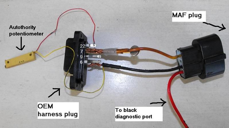
Nothing is plugged into the #9 socket?
MAF: Autothority
I'm about to finish this up with heat shrink and solder. Could you guys take a look at my Autothority MAF harness? My original harness was ripped apart by my headlights and I would like to make sure I got the wiring right. Is this how Autothority wires their MAF?
Nothing is plugged into the #9 socket?
 06-17-2008, 06:12 PM
#2
Addict
Rennlist Member
Rennlist
Site Sponsor
Rennlist Member
Rennlist
Site Sponsor
Yup looks good. I have one here out of a customer's car that we upgraded to a Vitesse Maf. Nothing connected where #9 would be on this one either.
08-07-2008, 10:33 PM
#3
Racer
Thread Starter
Join Date: Jun 2005
Location: New Jersey
Posts: 320
Likes: 0
Received 0 Likes
on
0 Posts
Ok,
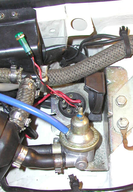
I have it wired up and plugged in except I forgot which hole in the "diagnostic port" I put that red wires pin into. I have attached what looks like the diagnostic port and hopefully someone with an MAF can pop open the black cap, and take a look which hole I should put my red wire in. The actual "diagnostic port" isn't labeled 1, 2, 3, 4, or 5. Those are numbers I made up. Let me know what each number does and what happens if I plug it into the wrong one.
note: I'm not sure that black thing is called the "diagnostic port". It can be found on the driver side between the windshield and the driver's side strut mount. It is much smaller than the one in my picture, and has a black plastic cap that needs to be opened to see the pin holes.
08-07-2008, 10:57 PM
#4
Addict
Rennlist Member
Rennlist
Site Sponsor
Rennlist Member
Rennlist
Site Sponsor
You are not grounding the sensor. You have 2 grounds, Power GND and sensor GND. I see the sensor ground missing.
08-07-2008, 11:07 PM
#5
Race Director
Wiring is correct...should be hole #4. It is pouring rain here, give me a sec and I'll run and check. As far as the grounds go I'll check that also...but you have everything I have on mine.
08-07-2008, 11:14 PM
#7
Racer
Thread Starter
Join Date: Jun 2005
Location: New Jersey
Posts: 320
Likes: 0
Received 0 Likes
on
0 Posts
How do you know the sensor isn't grounded, where should I look? I should have two black wires coming out of the MAF plug?
CPR - Let me know. You have an autothority maf? I was thinking 1 (the first plug closest to the passenger fender). Number 4 is the first plug closest to the driver's side fender.
fast951 - Would you know which plug in the diagnostic port?
Here is what I found on a different thread:
What would happen if I plug it into the wrong spot?
CPR - Let me know. You have an autothority maf? I was thinking 1 (the first plug closest to the passenger fender). Number 4 is the first plug closest to the driver's side fender.
fast951 - Would you know which plug in the diagnostic port?
Here is what I found on a different thread:
OK, when you look at the diagnostic port, a pin stands by itself. If you were to look at that pin to be at 12 o'clock, your connection should go to the next pin clockwise or at 2 o'clock.
I just went thru this myself and need to plug it. It is always a good idea to test for juice when the ignition is on just to make sure.
Raj
I just went thru this myself and need to plug it. It is always a good idea to test for juice when the ignition is on just to make sure.
Raj
Trending Topics
08-07-2008, 11:15 PM
#8
Race Director
The holes and not exactly laid out like you have them drawn but it appears to be your number 3. If you have a voltmeter, check the voltage of port 3 with the key off (should read 0) then with the key in the on position (don't start the car) it should read 11-13 volts. That ensures you are in the right one.
 08-08-2008, 12:31 AM
#11
Racer
Thread Starter
Join Date: Jun 2005
Location: New Jersey
Posts: 320
Likes: 0
Received 0 Likes
on
0 Posts
Did some more searching and found this, but it doesn't quite match what CPR is saying:
This image seems to show 1 as the power supply.
More searching and another quote:
So it seems like the 12v power supply is 1 in my picture. CPR isn't using 1 and has an autothority maf. Is it possible he is using the 5v power supply and that autothority requires a 5v supply?
This image seems to show 1 as the power supply.
More searching and another quote:
Run the positive wire over to the battery and see if the car starts. The MAF needs FULL 12.1-3 volts to function properly - it needs to be by itself. Just a quick connection to see if that corrects the problem.
I get 12v from the diagnostic port, 12v switched, thick red wire in the pic
I get 12v from the diagnostic port, 12v switched, thick red wire in the pic
So it seems like the 12v power supply is 1 in my picture. CPR isn't using 1 and has an autothority maf. Is it possible he is using the 5v power supply and that autothority requires a 5v supply?
Last edited by ZPmadA; 08-08-2008 at 01:09 AM. Reason: added another quote
08-08-2008, 08:54 AM
#13
Addict
Rennlist Member
Rennlist
Site Sponsor
Rennlist Member
Rennlist
Site Sponsor
08-08-2008, 09:12 AM
#14
Race Director
I'll upload some pics when I get off work today. I am not in a 5v slot as the MAF will not function on voltage less than 10v. Also mine is hardwired to the wire that formerly went to that port, as you will exp. some problems later on with the contacts. Get back to you.