
Custom lower and wider front suspension
 01-03-2008, 10:12 AM
#1
Pro
Thread Starter
Join Date: Aug 2002
Location: Netherlands
Posts: 589
Likes: 0
Received 0 Likes
on
0 Posts
I never really liked the front suspension of my 951.
As a racer, you look for toughness and adjustability. Exactly those two qualities are lacking in the standard Porsche suspension.
It happened to me twice in races in 2006. I took a hit on a front wheel by a competitor. The first one (caught nicely on video) cost me what would have been my first victory, the second five places.
Lucky for me it was in both cases the last heat of the day. After a hit on the wheel, the alignment is gone, and often also the caster block flange bent. You do not want to do an alignment, with the awkward eccentric in a pit box.
So when I started the investigations on my wide body project, I wanted this fixed.
I know a lot of people that go WB, actually just change the ET on their rims, or even worse use spacers. You do not have to be a math wizard (or perhaps you do) to see that this completely ruins the geometry of the front suspension: the turning point of the tire changes relative to the action point; the resulting momentum will break the tire carcass. And then there is bump-steer to worry about.
So the resulting demands were:
• Lowered pickup points
• Robust link to chassis
• Easy alignment
• Correction of the geometry for WB
I discussed this with Ad V. of VA Motorsport Engineering, who earns a fair bit of his money building suspensions for Dakar cars and SUV’s, and he came up with a very elegant and not even very expensive solution.
Instead of making an A-Arm he proposed to use two CrMb rods with uniballs. The actual arm, with a uniball for the balljoint on one side, and a mechanism with left and right threaded rod on the other side, making it even possible to easily adjust Track Width by an inch. The other rod acts as a caster–pushrod with uniballs on both sides, one left threaded, one right threaded. Adjustment of caster is now a matter of turning the rod. Camber adjustment is done with the top camber plates.
The suspension pickup points where moved up an inch.
The point in the aluminum sub frame was easy: We drilled a new hole, and welded supporting rings on both sides. Easy, if you know how to weld aluminum.
The replacement of the caster flange was quite a bit harder. We welded a structure, it could be best described as a box, made of a square profile in lieu of the flange. With a nut welded on top, only one M12 bolt is needed to fixate the caster rod, which now sits in the flange, instead of under it.
The final result looks quite elegant:
As can be seen, the fit of the sway bar was a challenge. We opted to re-bend the Weltmeister bar, and made a few flanges on top of the A-rod to connect it to. I am still looking for a different sway bar solution. The wider track width requires a wider sway bar. Ideas, anyone?
Conclusion: I am very satisfied with the result. At a cost that is not a lot higher then some of the aftermarket solutions I have a solution that fulfills all my needs and can do things that no standard solution can.
Alignment is a piece of cake, I even get a discount at the alignment shop. There is no creep in the alignment. After two track days the settings were still exactly where we put them.
An added advantage is that practically all items in the front suspension can be removed and put back without the need for realignment. As long as the rod lengths are unchanged, everything can be screwed back without a problem.
As a racer, you look for toughness and adjustability. Exactly those two qualities are lacking in the standard Porsche suspension.
It happened to me twice in races in 2006. I took a hit on a front wheel by a competitor. The first one (caught nicely on video) cost me what would have been my first victory, the second five places.
Lucky for me it was in both cases the last heat of the day. After a hit on the wheel, the alignment is gone, and often also the caster block flange bent. You do not want to do an alignment, with the awkward eccentric in a pit box.
So when I started the investigations on my wide body project, I wanted this fixed.
I know a lot of people that go WB, actually just change the ET on their rims, or even worse use spacers. You do not have to be a math wizard (or perhaps you do) to see that this completely ruins the geometry of the front suspension: the turning point of the tire changes relative to the action point; the resulting momentum will break the tire carcass. And then there is bump-steer to worry about.
So the resulting demands were:
• Lowered pickup points
• Robust link to chassis
• Easy alignment
• Correction of the geometry for WB
I discussed this with Ad V. of VA Motorsport Engineering, who earns a fair bit of his money building suspensions for Dakar cars and SUV’s, and he came up with a very elegant and not even very expensive solution.
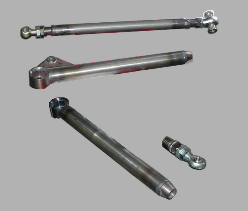
Instead of making an A-Arm he proposed to use two CrMb rods with uniballs. The actual arm, with a uniball for the balljoint on one side, and a mechanism with left and right threaded rod on the other side, making it even possible to easily adjust Track Width by an inch. The other rod acts as a caster–pushrod with uniballs on both sides, one left threaded, one right threaded. Adjustment of caster is now a matter of turning the rod. Camber adjustment is done with the top camber plates.
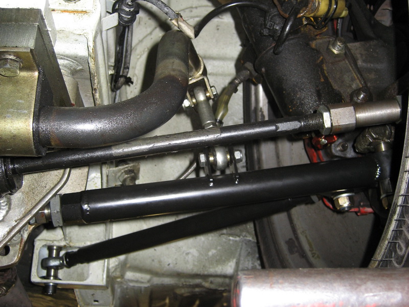
A arm components.
Top: Caster rod. Middle: Arm rod. Bottom: Arm rod still without flanges, adjustment mechanism
Top: Caster rod. Middle: Arm rod. Bottom: Arm rod still without flanges, adjustment mechanism
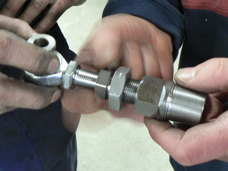
A-Rod adjustment mechanism in capable hands.
Turn middle nut to adjust lenght
Turn middle nut to adjust lenght
The suspension pickup points where moved up an inch.
The point in the aluminum sub frame was easy: We drilled a new hole, and welded supporting rings on both sides. Easy, if you know how to weld aluminum.
Sub frame with additional hole
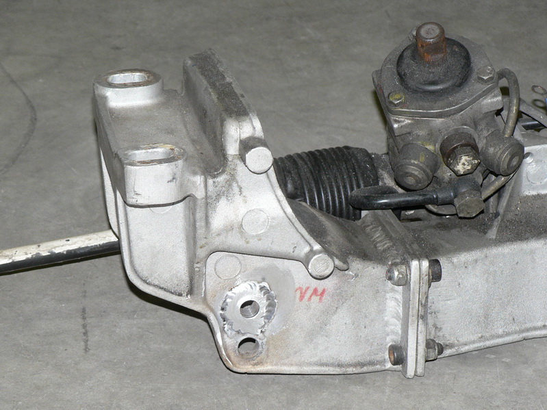
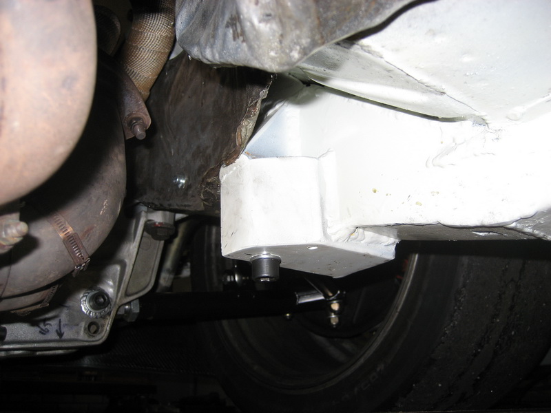
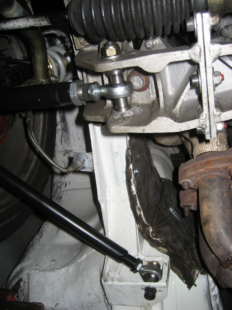
The replacement of the caster flange was quite a bit harder. We welded a structure, it could be best described as a box, made of a square profile in lieu of the flange. With a nut welded on top, only one M12 bolt is needed to fixate the caster rod, which now sits in the flange, instead of under it.
Bottom view of caster mount
Rear view of caster mount
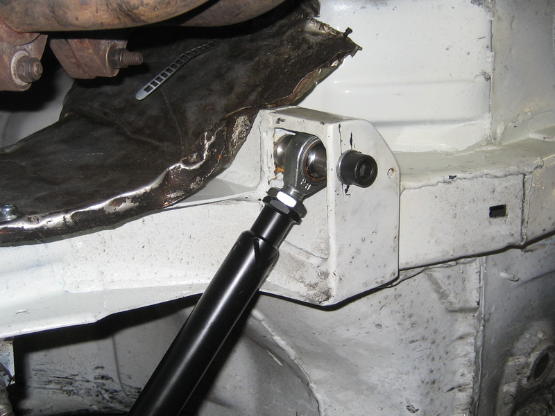
The final result looks quite elegant:
A-arm front view
As can be seen, the fit of the sway bar was a challenge. We opted to re-bend the Weltmeister bar, and made a few flanges on top of the A-rod to connect it to. I am still looking for a different sway bar solution. The wider track width requires a wider sway bar. Ideas, anyone?
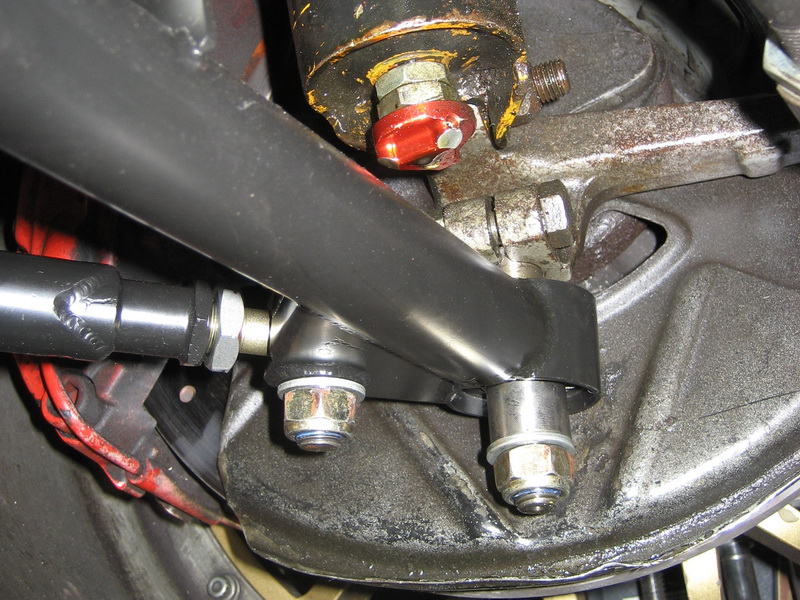
A-arm bottom view: Up close the mounts look incredibly solid
Ball joint section.
Note: By changing the bushings from the ball joint, the bump steer can be changed.
Note: By changing the bushings from the ball joint, the bump steer can be changed.
Conclusion: I am very satisfied with the result. At a cost that is not a lot higher then some of the aftermarket solutions I have a solution that fulfills all my needs and can do things that no standard solution can.
Alignment is a piece of cake, I even get a discount at the alignment shop. There is no creep in the alignment. After two track days the settings were still exactly where we put them.
An added advantage is that practically all items in the front suspension can be removed and put back without the need for realignment. As long as the rod lengths are unchanged, everything can be screwed back without a problem.
 01-03-2008, 10:30 AM
#2
Rennlist Member
all i can say is wow. I think thats the best setup i have seen on a 951. one question you said that when you got hit the caster block flange got bent. Now with your new setup what would happen if you got hit in the same spot? Some thing got to give. Please dont get offended i am just thinking out loud.
01-03-2008, 10:34 AM
#3
Pro
Thread Starter
Join Date: Aug 2002
Location: Netherlands
Posts: 589
Likes: 0
Received 0 Likes
on
0 Posts
all i can say is wow. I think thats the best setup i have seen on a 951. one question you said that when you got hit the caster block flange got bent. Now with your new setup what would happen if you got hit in the same spot? Some thing got to give. Please dont get offended i am just thinking out loud.
01-03-2008, 10:35 AM
#4
Rennlist Member
01-03-2008, 10:43 AM
#5
Pro
Thread Starter
Join Date: Aug 2002
Location: Netherlands
Posts: 589
Likes: 0
Received 0 Likes
on
0 Posts
I also have a wider bumper beam to protect the front end of the wheel. Very effective, has been outlawed in rallyracing, but is legal in the track. We are not supposed to touch, eh?

Trending Topics
01-03-2008, 10:50 AM
#9
Rennlist Member
01-03-2008, 12:24 PM
#11
Drifting
Join Date: Mar 2006
Location: midwest
Posts: 2,931
Likes: 0
Received 0 Likes
on
0 Posts
Hey hans - Love the ingenuity, and approach, and adjust-ability
I have one concern with your arm setup that perhaps you can shed light on.
With all A-arm setups you have a cross brace between the outer arms making the A
Your "V" setup (without a cross support) seems to me will not share the load between the mount points. All load will be transferred to the single rear mount point. It is hard to tell from the pics, but the rear mount point,bar,and rod end size do not appear to be engineered to handle those loads. (can be very high especially in a race environment, wheel impacts, jumping rumble strips, etc)
A short rod with threaded rod ends and tabs welded to each of the outer arm would still allow all adjust-ability and perhaps help to equalize the load. Still may not be adequate.....
Just curious if this is considered? I don't claim to be a suspension expert, but have been around lots of different racing.... my gut says the rear mount bar needs to be much larger with a reinforced mount point, or cross brace arms the share load
Thanks for sharing Hans. Would appreciate your thoughts as I would love to do something similar, but have not figured out exactly what
01-03-2008, 12:59 PM
#12
Pro
Thread Starter
Join Date: Aug 2002
Location: Netherlands
Posts: 589
Likes: 0
Received 0 Likes
on
0 Posts
Hey hans - Love the ingenuity, and approach, and adjust-ability
I have one concern with your arm setup that perhaps you can shed light on.
With all A-arm setups you have a cross brace between the outer arms making the A
Your "V" setup (without a cross support) seems to me will not share the load between the mount points. All load will be transferred to the single rear mount point. It is hard to tell from the pics, but the rear mount point,bar,and rod end size do not appear to be engineered to handle those loads. (can be very high especially in a race environment, wheel impacts, jumping rumble strips, etc)
A short rod with threaded rod ends and tabs welded to each of the outer arm would still allow all adjust-ability and perhaps help to equalize the load. Still may not be adequate.....
Just curious if this is considered? I don't claim to be a suspension expert, but have been around lots of different racing.... my gut says the rear mount bar needs to be much larger with a reinforced mount point, or cross brace arms the share load
Thanks for sharing Hans. Would appreciate your thoughts as I would love to do something similar, but have not figured out exactly what
I have one concern with your arm setup that perhaps you can shed light on.
With all A-arm setups you have a cross brace between the outer arms making the A
Your "V" setup (without a cross support) seems to me will not share the load between the mount points. All load will be transferred to the single rear mount point. It is hard to tell from the pics, but the rear mount point,bar,and rod end size do not appear to be engineered to handle those loads. (can be very high especially in a race environment, wheel impacts, jumping rumble strips, etc)
A short rod with threaded rod ends and tabs welded to each of the outer arm would still allow all adjust-ability and perhaps help to equalize the load. Still may not be adequate.....
Just curious if this is considered? I don't claim to be a suspension expert, but have been around lots of different racing.... my gut says the rear mount bar needs to be much larger with a reinforced mount point, or cross brace arms the share load
Thanks for sharing Hans. Would appreciate your thoughts as I would love to do something similar, but have not figured out exactly what
According to him the stiffness of the structure between the two mounting points is such, that any reinforcement of the A (or in this case V) arm contributes very little. The majority of the load would come to the front rod and that is a lot stronger than the original aluminum setup.
He has build the same solution on rally cars, where the loads are much higher.
So I decided to trust him.
 01-03-2008, 01:16 PM
#14
Drifting
Join Date: Mar 2006
Location: midwest
Posts: 2,931
Likes: 0
Received 0 Likes
on
0 Posts
I had the same discussion with the guy who made this.
According to him the stiffness of the structure between the two mounting points is such, that any reinforcement of the A (or in this case V) arm contributes very little. The majority of the load would come to the front rod and that is a lot stronger than the original aluminum setup.
He has build the same solution on rally cars, where the loads are much higher.
So I decided to trust him.
Thanks for reply