When you click on links to various merchants on this site and make a purchase, this can result in this site earning a commission. Affiliate programs and affiliations include, but are not limited to, the eBay Partner Network.
Hi---and thx in advance-----does the speed sensor control the fuel pump, o2 and turbo water cooler pump? If these items are hardwired can the speed sensor be deleted?
Many thx,
No, speed sensor sends signal to DME which then runs fuel pump, but the speed and ref sensors are used constantly by the DME or whatever management you’re using.
Hi---and thx in advance-----does the speed sensor control the fuel pump, o2 and turbo water cooler pump? If these items are hardwired can the speed sensor be deleted?
Many thx,
,QUOTE=cjb3;14648741]The one that counts the starter ring teeth[/QUOTE]
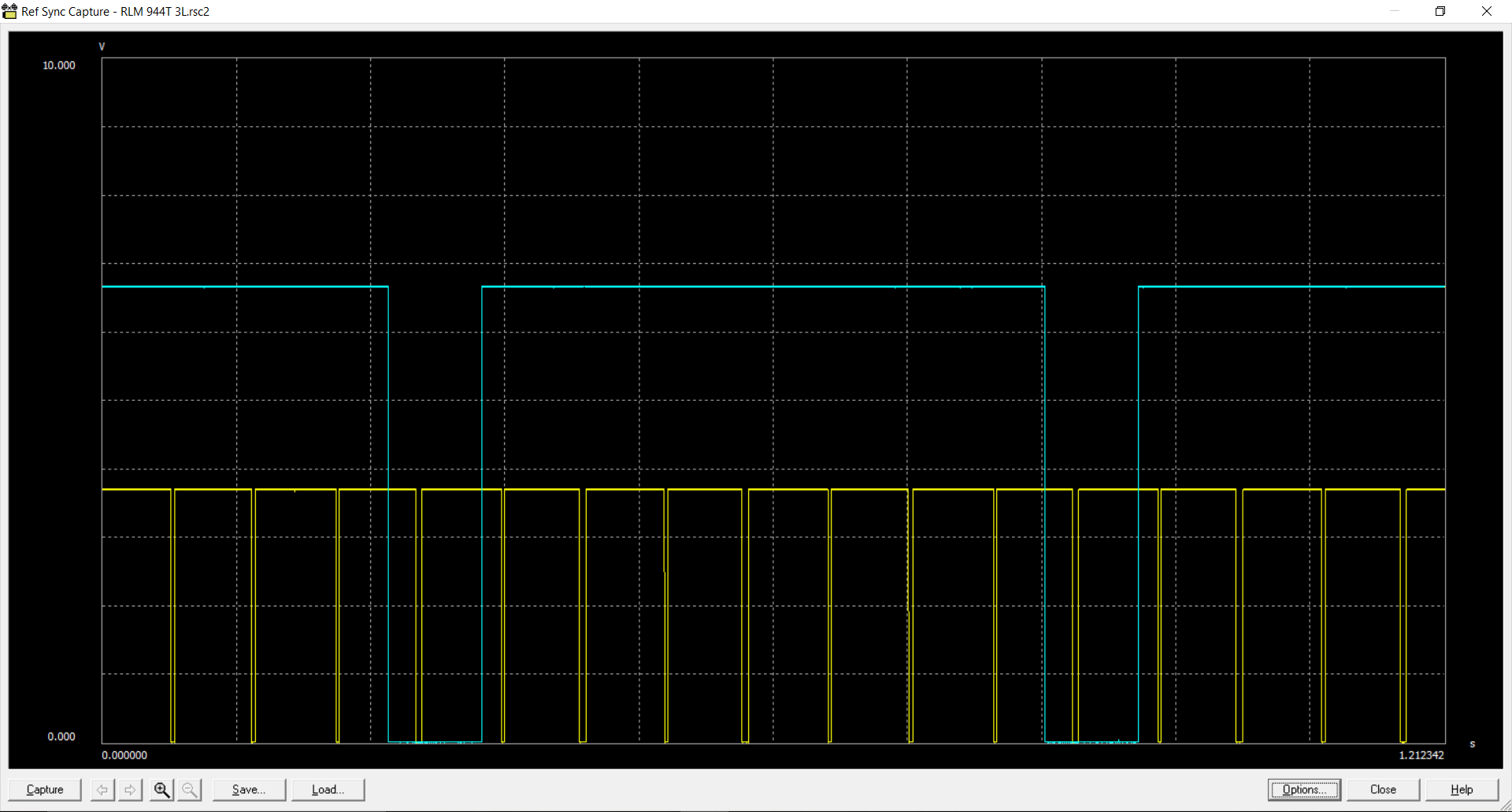
Then yes it is a must have. You have 2 sensors there that I define as a reference sensor and a sync sensor. The sync (blue) is telling the ECU where TDC is in the sequence. The ref (yellow) is telling the ECU what degree the engine is located. The chart below is for my motor. It is counting 4 pts per per revolution for a total of 8 pts per 720 degrees for TDC piston one.
Hi---and thx in advance-----does the speed sensor control the fuel pump, o2 and turbo water cooler pump? If these items are hardwired can the speed sensor be deleted?
Many thx,
CJ
The flywheel speed sensor does not control any of the items you mention. A look at the wiring diagram would verify that.
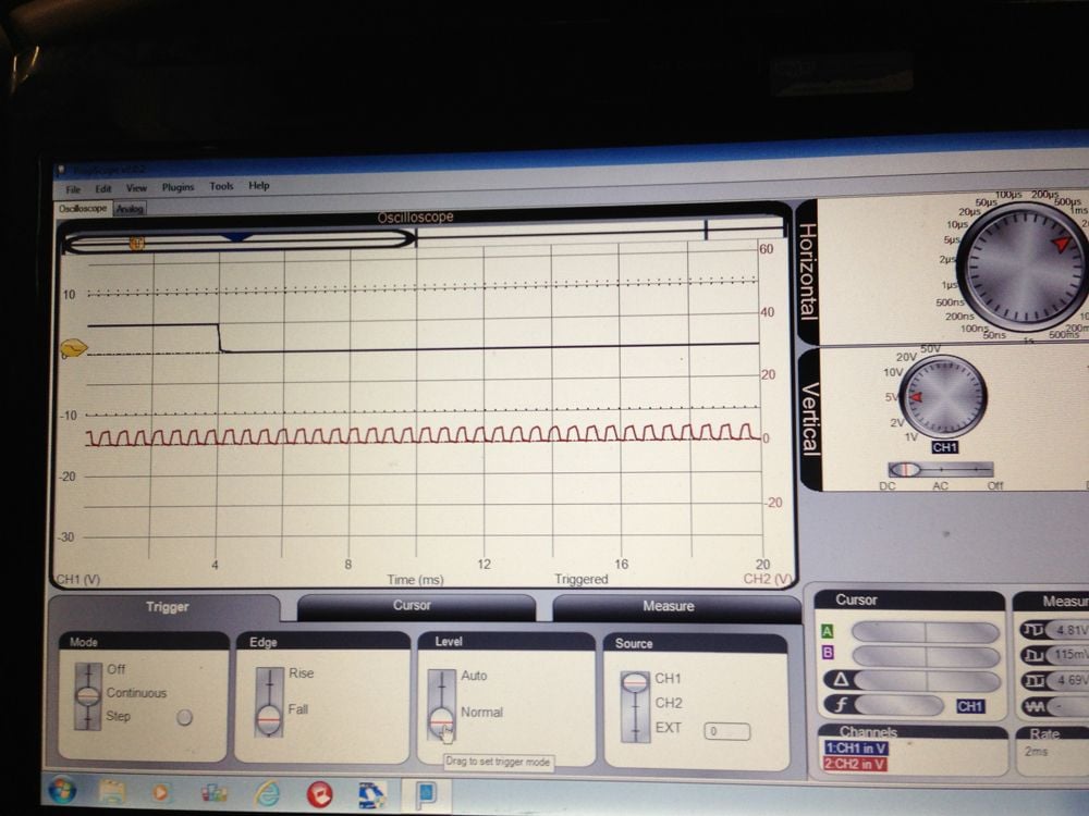
RLM, where are you picking up those signals? Not to geek out too heavily, but not sure what your yellow signal represents? Your graph shows essentially and 8:1 ratio of pulses, rather than 132:1. The starter ring sensor produces 132 pulses per revolution on a 951 (for an actual resolution of 2.72 degrees, from which the DME creates higher virtual resolution based on the time between ticks). Here's a screen shot showing the actual speed and reference sensor signals as seen by the interrupt pins on the DME's 8051. The speed and ref sensors create sine waves (as shown in the FSM) but those sine waves are processed by the mysterious S100 chip in the DME (the only chip aftermarket DME suppliers re-use), which turns the sine waves into square digital pulses that are fed directly to the hardware interrupt pins on the DME's 8051. This screen shot shows what the 8051 sees from the two sensors...
Top signal is the TDC and the bottom is the ring gear.
At any rate, to the OP, as others have said, these sensors have nothing to do with the fuel pump/O2/coolant pump operation -- other than that the motor won't run without them.
You are correct I stated that in my write up. I am running a Motec off of my cam gear. I have 8 magnets inserted in my cam tower gear for my reference signal and one magnet where the rotor went for my sync. Has worked great for the last 5 years. There are about a dozen cars out there with the same set up.
You are correct I stated that in my write up. I am running a Motec off of my cam gear. I have 8 magnets inserted in my cam tower gear for my reference signal and one magnet where the rotor went for my sync. Has worked great for the last 5 years. There are about a dozen cars out there with the same set up.
Ah, got it. I thought you were talking about a stock 951 set up and was scratching my head... The DME/KLR is impressive for its day, and did amazing things with an 8-bit 8051 processor, but a modern MoTec box has more processing power in its little pinky...
You are correct I stated that in my write up. I am running a Motec off of my cam gear. I have 8 magnets inserted in my cam tower gear for my reference signal and one magnet where the rotor went for my sync. Has worked great for the last 5 years. There are about a dozen cars out there with the same set up.
Hi Bob,
Any more info on this setup? Links to other Rennlist discussions are cool, I sometimes fail at searching the archives effectively .
Sorry to be off topic. Bob, any concern about timing accuracy with only 4 references per revolution? That's only giving each cylinder its spark timing within 90 deg every cycle. Plus belt slop/hysteresis. It's obviously working no problem but I'm just curious from an armchair engineering perspective.

 12-04-2017, 09:06 PM


 .
.