S2 Supercharger Build Thread UPDATE 22 Feb 2012 - DYNO PLOTS
 12-03-2011, 02:51 AM
#16
Three Wheelin'
Thread Starter
Thanks a lot Eric for the information.
I've installed a Split Second MAF on mine, with a Large Band lambda sensor and zt-2 zeitronix. I think it's a good way to begin the sc modification, but your solution is cheaper and works great too. If you're interested by the MAF wiring on the future, do not hesitate to ask...
Sadly, i can't start the sc installation now, my engine is on work, but i follow you with interest!

 12-03-2011, 07:52 AM
#17
Three Wheelin'
Thread Starter
Spent some time trying to figure out where to mount the AFM. My first thought was below, but there are two problems with this. Firstly getting the outlet to run in front of the steering tie rod and between the alternator and sway bar is a really tight fit. I recall Henk had to install a smaller alternator to get this to work. Secondly, mounting the AFM below and then getting the outlet to go up through the hole in the bottom of the "well" behind the left headlight is also tight.
Thought I might need to go MAF, but one last shot at installing the AFM - this time from above.
And thanks to Pauly for the Autobarn tip for the AFM plate. Found a blank one I can drill to suit for $25.
The AFM j-u-s-t clears the hood by about 10mm. Will need some foam padding there. Intake pipe to AFM will utilise the hole that is there for the 951 with an airfilter placed between the fender/guard, chassis and wheel lining.
12-04-2011, 07:48 PM
#18
3rd Gear
Join Date: Jan 2010
Location: Bordeaux - France
Posts: 3
Likes: 0
Received 0 Likes
on
0 Posts
Hi Eric,
MY MAF run with a PSC1 calibrator which convert MAF signal to the DME. You can monitor ans set up the AFR with a software provided with the PSC1.
This is a link to explain :
http://www.splitsec.com/technotes/AF...Conversion.pdf
My MAF is a Ford one,pics with reference...
http://i68.servimg.com/u/f68/11/18/36/38/snc00410.jpg
http://i68.servimg.com/u/f68/11/18/36/38/snc00411.jpg
http://i68.servimg.com/u/f68/11/18/36/38/snc00420.jpg
12-06-2011, 12:07 AM
#19
Three Wheelin'
Hi Eric, do you think a Turbo (951) airbox and AFM would fit? From photos, this should give you enough room. Only concern would be clearance at the RF corner of the cam cover. You should still be able to use the S2 AFM if you can source a Turbo airbox with the transition pipe.
I like this idea because any restriction upstream of the S/C helps to fatten the boost curve.
In the meantime I'll look closer at the MAP-ECU3. It can datalog as well, should mean I would only need an Innovate MTX-L rather than the full-blown LM2.
I also like the idea of relocating the throttle so that it is on the upstream side of the S/C. This eliminates the need for blowoff/recirc valves.
I reckon this can be achieved by making a bracket to move it laterally to the right (as viewed from the front) and having a straight shot from the intercooler to the plenum.
Downsides are a) airleaks downstream of the throttle/AFM are a problem and b) ^%Y%^ing AFM gets in the way. MAP-ECU3 would solve both these.
Whaddayarekkin?
Cheers,
12-06-2011, 07:58 AM
#20
Three Wheelin'
Thread Starter
Mike,
It is really tight in there when you start running hoses to the intercooler. It would be awesome to run the turbo box as it would then look totally stock. I think the AFM size is the same. I would have to look at a turbo engine again to check. I think the problem will be running the inlet hose (76mm) to the SC inlet which is in the rear. The only way up is to run a 90 degree bend out of the SC and tilt it 45 degrees clockwise (viewed from front) then have a 45 degree aluminium pipe and connect that to another 90 degree bend. Even with this approach I still need to shift the wiring harness to the headlights etc a little to get enough room. I also have used 76 to 64mm 90 bends to get enough room!
I don't think anyone has used the AFM with a SC conversion before on an S2, so it will be interesting. I'm only going to run a 100mm pulley to start with (to get tuning right), but I should get a little bit of inlet restriction to help boost midrange.
Moving the TB would be difficult in maintaining the throttle cable and linkages. A dual throttle would be ideal - ie keep stock and add another to work in parallel prior to or just after the AFM. Again, as you say not much room.
I got some silicone hoses/bends etc today and trial fitted a couple. I think it is all going to fit, with maybe 20mm clearance to hood. Just waiting on some more aluminium pipes and connectors from the UK and a couple of bends from the US (couldn't seem to get 60 degree bends anywhere but this place).
Not sure on the MAP-ECU3. Isn't it just a signal interceptor? I can adjust timing and fuel in the motronic, so not sure what this would do apart from intercept the AFM signal voltage?
12-07-2011, 04:01 AM
#22
Three Wheelin'
Hi Eric,
Yep, understand where you're at with the pipework. Space is at a premium! I am considering using a fabricated banjo-style inlet on the S/C, and piping with 2" to the I/C just to create some space. I calculated a restrictor at 45mm so 50mm tube is ok.
The MAP-ECU3 is an AFM eliminator - converts to MAP so creates some more space. It also has datalogging (but so does your LM2) and tuning (but you're doing this in Motronic).
Yep dual throttle would be sweet - brings back memories of vacuum secondaries on carburetors...
12-21-2011, 04:24 AM
#23
Three Wheelin'
Thread Starter
A little bit of progress, but still awaiting delivery of some pipes and silicone hose.
Oil cooler has been installed in the left hand side using the existing support that mirrors the support for the engine cooler on the RHS. Simple brackets fabricated using 40x3mm galvanised steel flat bar and utilising the existing holes in the body. The cooler is a very tight fit but almost looks like it was made to go there. Cooling ducts in the front bumper cover line up nicely with the cooler. Some rubber grommets help isolate the cooler from vibration and give it some give between the radiator support frame and bracket.

Also mocked up the hoses for the intake. It is amazing how much you can outlay on the various hoses, couplers and clamps. It would have been cheaper I think fabricating up most of this as hard lines, but at least this way I can easily adjust the setout.

The intake area is really tight. I am having to use a series of 45 degree bend and a 90 degree bend to get the pipework between the AFM and behind the front guard/fender. The cone filter will sit in the wheel well in front of the inner wheel liner and behind the front bumper cover. The hoses shown are not necessarily the right size, but show how it will fit together. I couldn't find anywhere to put the rotrex oil reservoir except in this busy little corner. It just squeezes in and is supported partly off the AFM. It may require a single hole drilled in the body for the lower bracket support.

From here on there won't be much progress for the next week or two as I am awaiting additional parts.
Oil cooler has been installed in the left hand side using the existing support that mirrors the support for the engine cooler on the RHS. Simple brackets fabricated using 40x3mm galvanised steel flat bar and utilising the existing holes in the body. The cooler is a very tight fit but almost looks like it was made to go there. Cooling ducts in the front bumper cover line up nicely with the cooler. Some rubber grommets help isolate the cooler from vibration and give it some give between the radiator support frame and bracket.
Also mocked up the hoses for the intake. It is amazing how much you can outlay on the various hoses, couplers and clamps. It would have been cheaper I think fabricating up most of this as hard lines, but at least this way I can easily adjust the setout.
The intake area is really tight. I am having to use a series of 45 degree bend and a 90 degree bend to get the pipework between the AFM and behind the front guard/fender. The cone filter will sit in the wheel well in front of the inner wheel liner and behind the front bumper cover. The hoses shown are not necessarily the right size, but show how it will fit together. I couldn't find anywhere to put the rotrex oil reservoir except in this busy little corner. It just squeezes in and is supported partly off the AFM. It may require a single hole drilled in the body for the lower bracket support.
From here on there won't be much progress for the next week or two as I am awaiting additional parts.
01-03-2012, 07:14 AM
#26
Three Wheelin'
Hi Eric, looks like you weren't able to plumb in the intercooler the "right" way round? (inlet/outlet)
Doesn't that mean you'll generate vacuum rather than boost?
Doesn't that mean you'll generate vacuum rather than boost?
01-03-2012, 07:24 AM
#27
Three Wheelin'
Thread Starter
Mikey - yes but because we are down under I think it works out neutral
Minor update.
Most parts have now been received with the exception of the k&n filter. I had to order a specific size so that it would fit behind the fender/guard.
I fabricated brackets to support the AFM using the original bracket mount point on the frame rail as well as the coolant tank support stud. I also wired up an extension to the AFM and made a takeoff to connect to the new AIT which will be installed just before the TB.
Most of the piping is now in. There is literally only millimeters clearance between the SC out, AFM to SC and intercooler to TB piping. I had to cut the headlight bracket "corner" off to get enough room for the intake piping at the AFM inlet. The oil reservoir only just fits and there is probably 10mm clearance to the hood from the AFM. All that is left to do is to weld some takeoffs into the aluminium tubing for the BOV and crankcase breather connections and install the oil lines to the Rotrex and cooler and tighten up all the clamping bands.
I expect to have it finished in less than 2 weeks. First race is on 28 January so it will be tight getting it tuned in time.
01-03-2012, 10:03 AM
#28
Drive-by provocation guy
Rennlist Member
Rennlist Member
Join Date: Apr 2002
Location: NAS PAX River, by way of Orlando
Posts: 10,439
Likes: 0
Received 0 Likes
on
0 Posts
I guess since you are able to do all the work yourself the sc approach was more cost effective than just picking up a 951?
01-03-2012, 06:30 PM
#29
Three Wheelin'
Thread Starter
On most tracks the s2 is quicker than the turbo (stock) due to the accelertion out of corners. I would have to buy a turbo and spend more money upgrading it to get to the performance i hope to get out of the sc. S2 and 951s go for over $20k here in oz as well so to make a dedicated track car would end up costing quite a bit more.
I'm also not a big fan of the lag in the 951.
I'm also not a big fan of the lag in the 951.
01-06-2012, 04:59 AM
#30
Three Wheelin'
Thread Starter
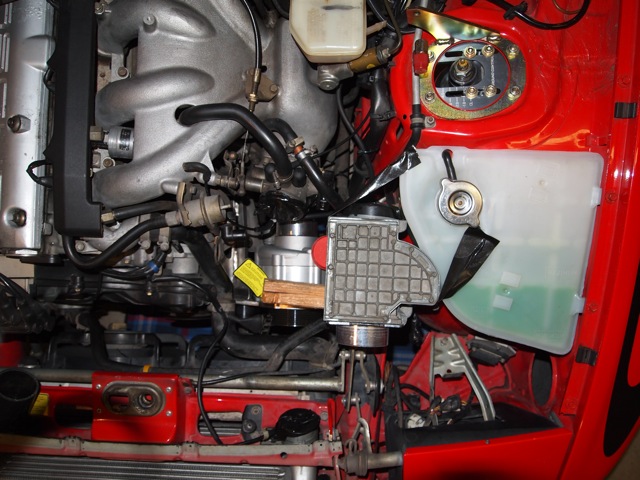
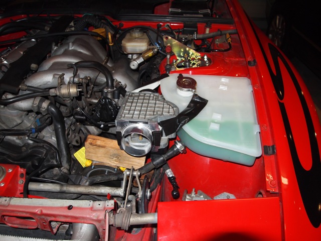
Some pics to show just how tight everything is.
Air intake - on reflection the filter looks a little small. Not sure if I can get a bigger one to fit, but perhaps it will work like a restrictor plate by increasing loss at high rpm, thereby allowing more boost in the midrange.

Not much space between TPS, intake, AFM and pipes. Note cut headlight bracket.


Air intake - on reflection the filter looks a little small. Not sure if I can get a bigger one to fit, but perhaps it will work like a restrictor plate by increasing loss at high rpm, thereby allowing more boost in the midrange.
Not much space between TPS, intake, AFM and pipes. Note cut headlight bracket.

