'87 Intake Removal, Repairs, Installation Procedure (w/pics)
 01-21-2009, 12:57 PM
#61
Addict
Rennlist Member
Rennlist Member
Dwayne, always admired your very detailed instructions when posting in the past and this is just as good.
The timing on the throttle body repair and what bearing to use is perfect and very useful.
Bearings will be on my next order to Roger.
Thanks/Peter
The timing on the throttle body repair and what bearing to use is perfect and very useful.
Bearings will be on my next order to Roger.
Thanks/Peter
 01-21-2009, 02:04 PM
#62
Under the Lift
Lifetime Rennlist
Member
Lifetime Rennlist
Member
I made one interesting discovery: Roger's flappy bearings with seals are the same size as the bearings in the throttle plate body. Has anyone else tried to replace the throttle plate bearings with Roger's Flappy bearings?? The results of the repair were EXCELLENT - cured the leak! From now on, I have 4 of Roger's sealed bearings on hand for an intake job (2 for the flappy and 2 for the throttle plate).
01-21-2009, 02:11 PM
#63
Addict
Rennlist Member
Rennlist
Site Sponsor
Rennlist Member
Rennlist
Site Sponsor

Your tech tips / photos just keep getting better and better and they were GREAT to start with ! Sunday the 25 TH POC is at the Streets of Willow.... I will be there 
01-21-2009, 02:33 PM
#64
Three Wheelin'

Dwayne
what is the best way to take the bearings out without damaging the aluminum.
Ive been trying and trying and the bearing doesnt want to move. the aluminum keeps getting damaged. all the bearings are out except the steel shell.
what is the best way to take the bearings out without damaging the aluminum.
Ive been trying and trying and the bearing doesnt want to move. the aluminum keeps getting damaged. all the bearings are out except the steel shell.
01-21-2009, 07:57 PM
#65
Three Wheelin'
Thanks Dr. Bob
I did heat the whole thing up in the kitchen oven to 300 F. but they just did not wana come out, I did the same with the intake and with 3 or 4 taps they came out, but not this time. I made the attempt 3 (heating in the oven) times but the bearing lip keep bending and breaking, non of the two bearings wanted to move.
I took them out finally. but i did it from the top of the bearing, meaning that I had to use a very thin sharp flat head screw driver to squish it in between the bearing wall and the aluminum wall bend the shell and break it. yes some aluminum got scratched in were the bearing goes. one off them came out easy doing this but the other one did not wana come out at all. I don’t know why Im not lucky with these bearings.
Sorry Dwayne I’m not trying to hijack your thread.
About the fuel lines I did exactly the same as you did, but since I had some left over I was wandering why? Maybe the kit is for all models, and some might require more lines to be changed.
cant wait to see how your timing belt thread will look like.
01-21-2009, 09:48 PM
#66
Rennlist Member
Thread Starter
Join Date: Sep 2007
Location: Ridgecrest, California
Posts: 1,363
Likes: 0
Received 143 Likes
on
28 Posts
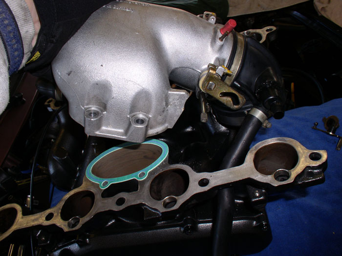
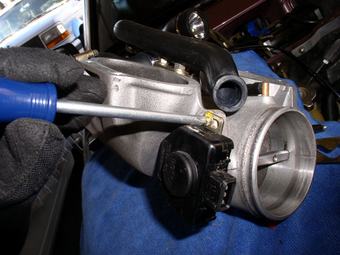
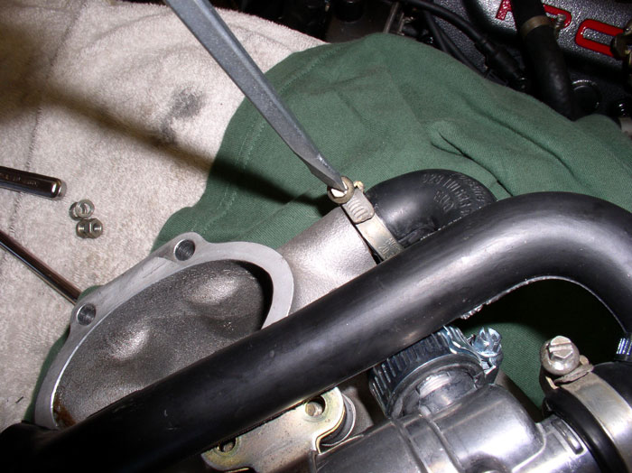
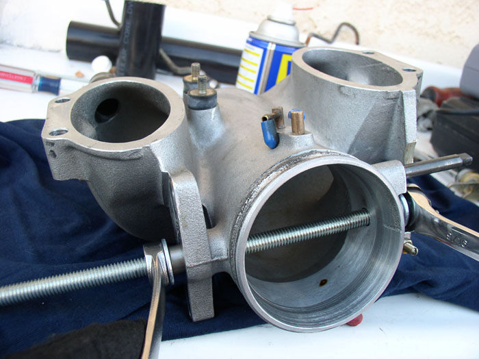
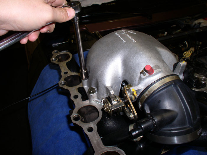
If you haven't already separated the Throttle Body from the intake, now's the time to do it. Remove the four 13mm bolts that hold the Throttle Body to the Intake (2 on each side)
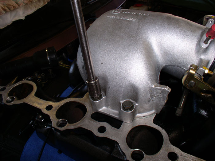
Remove the intake, guiding any hoses still attached through the intake runners.
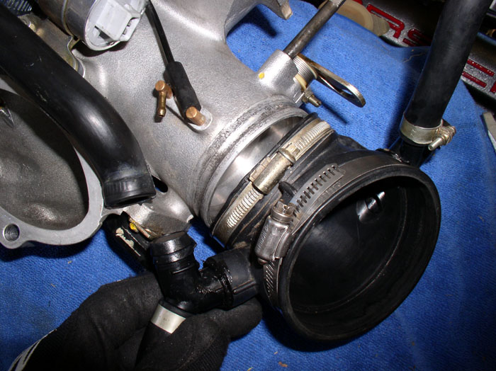
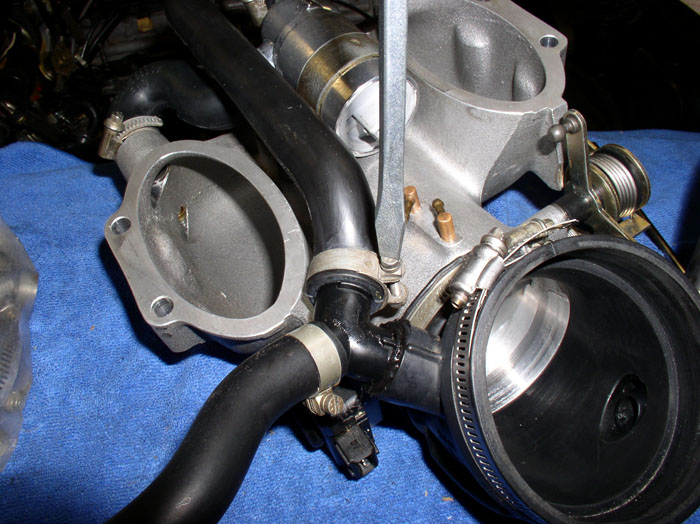
Loosen the clamp on the ISV intake hose at the Air Guide Cowl. Disconnect the hose.
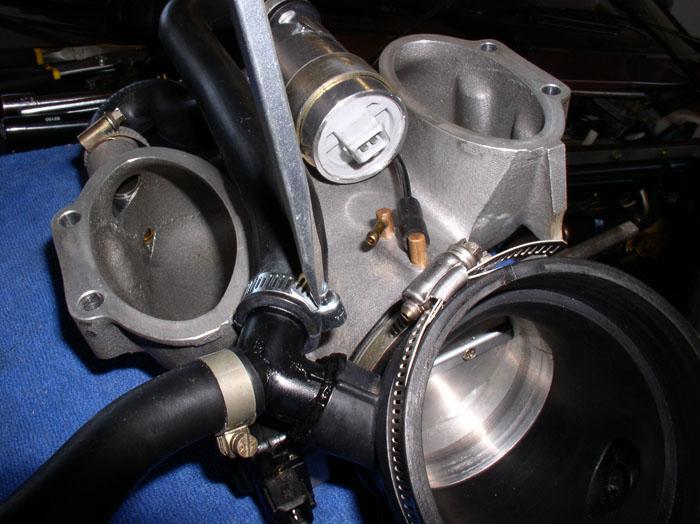
Loosen the Air Guide Cowl clamp at the Throttle Body.
Remove the Air Guide Cowl from the Throttle Body.
Check the operation of the throttle plate and Throttle Position Sensor. Note any sticking or scraping - it should operate smoothly. Listen for the "click" of the Throttle Position Sensor as you begin opening the throttle plate. Make note of when the "click" occurs. It should click at about 1 degree of movement of the throttle plate. The "click" is the Idle contact functioning in the TPS - letting the EZK and LH know when the car is no longer idling and to use a different fuel/injector map. If everything checks out ok, you'll have a baseline of how it should operate when you put it back together. Many times I have taken something apart without noting how it operated before and when I put it back together, I wasn't sure if it was operating better or worse than before the repair. So, now I baseline.
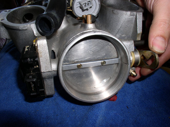
Remove the throttle plate by first removing the 2 phillips screws that attach it to the throttle plate shaft.
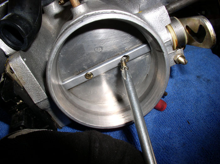
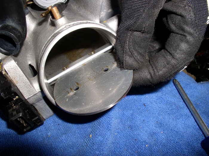
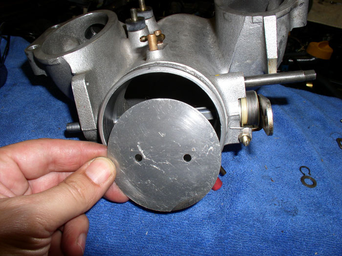
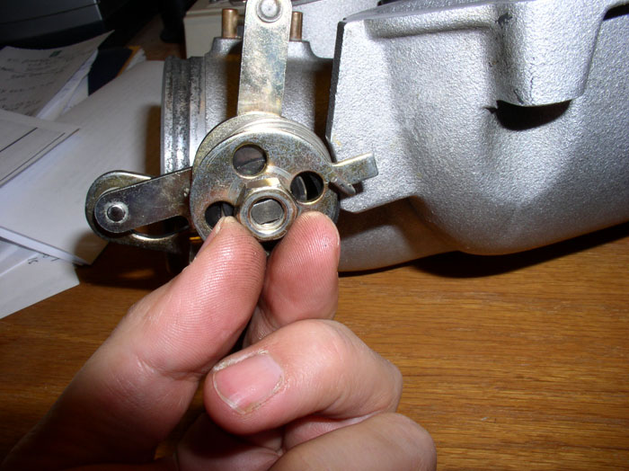
Rotate the throttle plate shaft 90 degrees and pull the throttle plate out. Notice the edges of the plate are camfered. You will want to make note of the orientation of the plate as you pull it out in order to get the camfers correct when you re-install the plate later. The easy way to do this is to note that there is a recessed arc cut into the front of the plate (look at the bottom half of the front of the plate). Simply ensure this arc is facing forward and at the bottom when you re-install the plate.
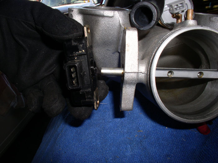
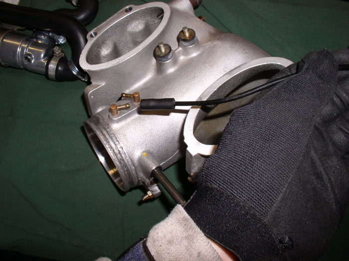
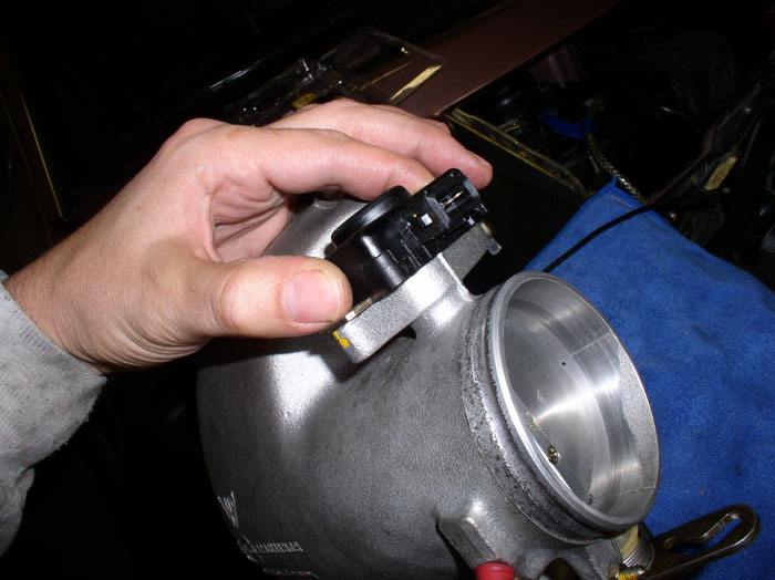
Next, remove the TPS by first removing the 2 phillips screws that secure it to the throttle body. Before you remove the screws, note the general orientation of the TPS on the throttle body. The mounting tab on the TPS is slotted so it can be adjusted to get the 1 degree of deflection on on the throttle plate before breaking idle contact just right. By noting the general orientation, on removal, you can get the TPS "close" to it's original location on re-install and simply fine tune the orientation from there. We'll discuss this when it's re-installed.
Remove the TPS by pulling out away from the throttle body.
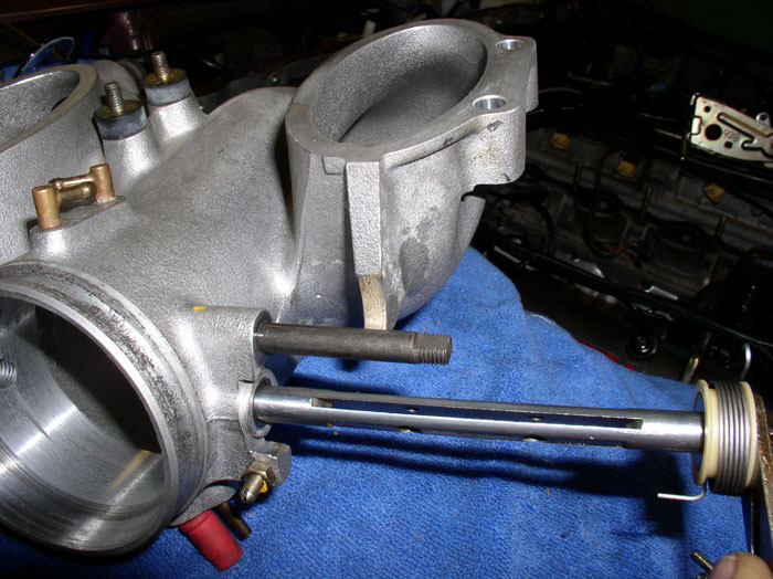
Next, remove the small circlip that holds the throttle plate shaft in place. Use an appropriately sized circlip pliers. I had to use my smallest set.
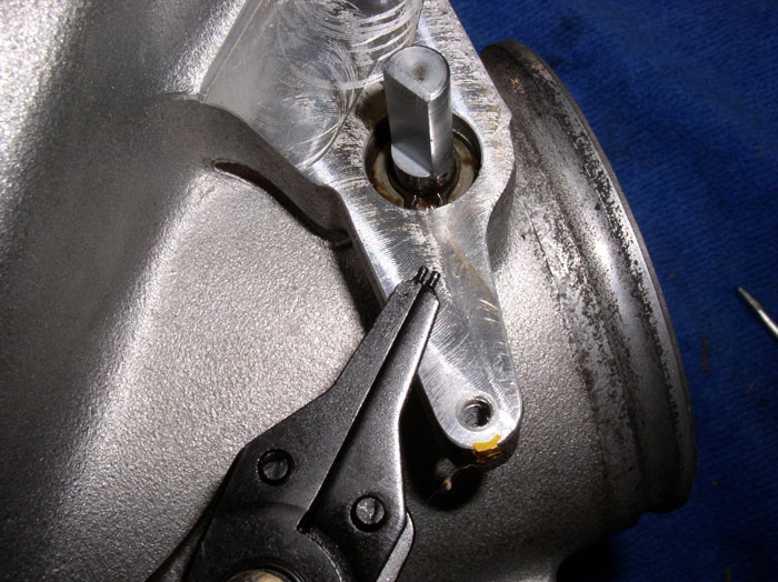
The circlip is thin and can be damaged if stretched too much so be careful on removal. It doesn't seem to be the same kind of spring metal I find on other circlips - (maybe because it's so small). I found that it was slightly distorted/stretched upon removal but when I re-installed it, I could bend it back into shape with no problem.
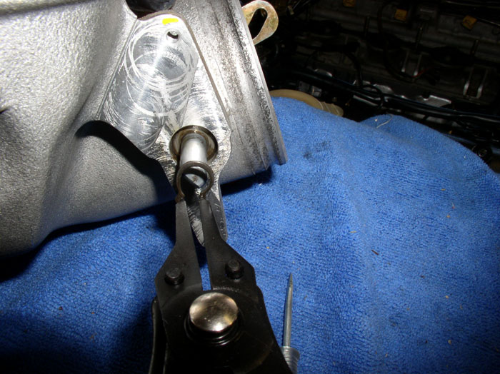
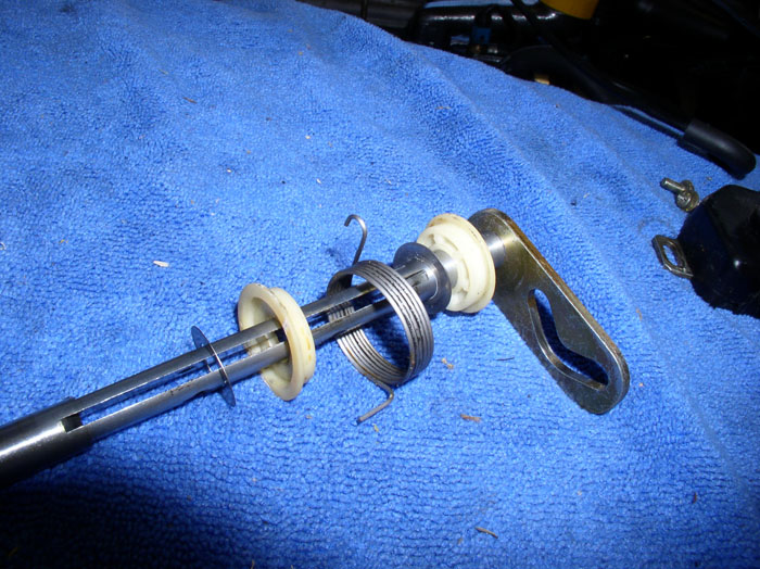
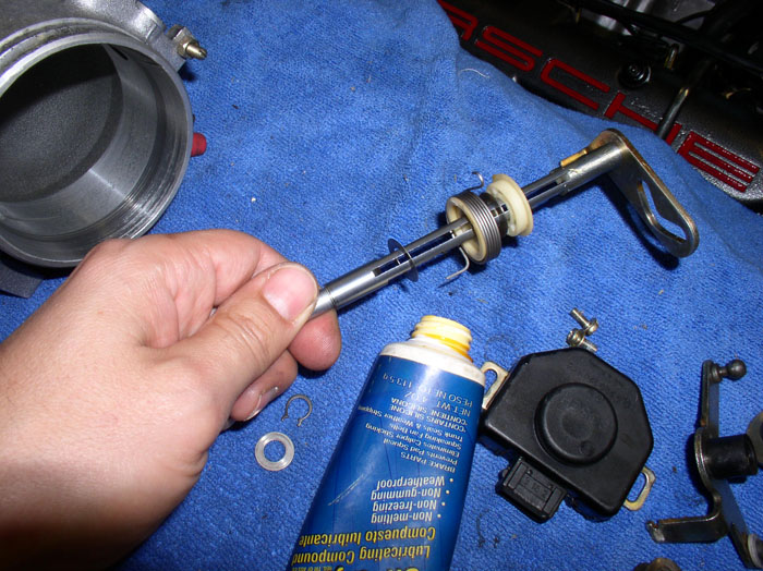
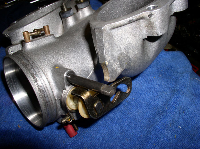
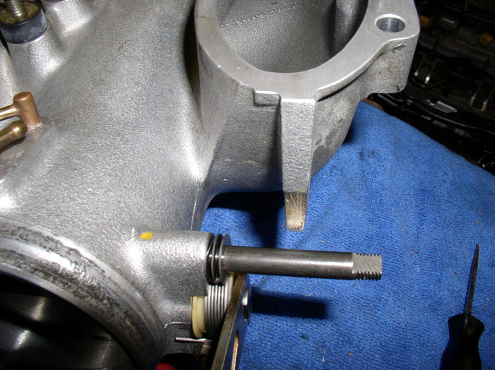
Now you can remove the throttle plate shaft by simply pulling it out as shown.
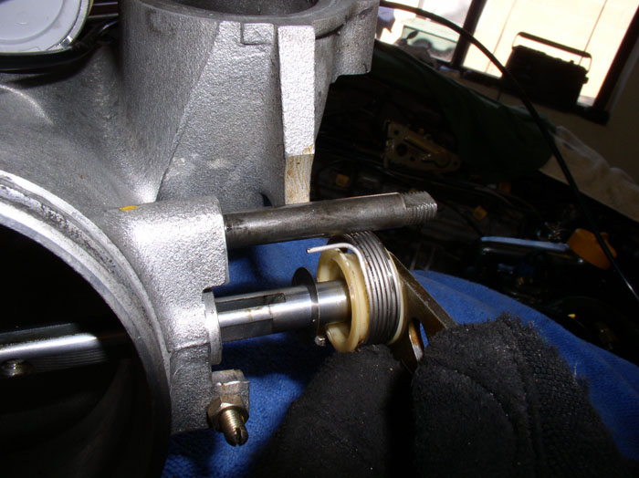
After you have the shaft out, note the order of the plastic washers, metal washers and spring as shown (in case you want to disassemble and clean). Here's the order....
Under the circlip (on the TPS side), remove the flat washer that sits on top of the bearing.
continued......
Remove the intake, guiding any hoses still attached through the intake runners.
Loosen the clamp on the ISV intake hose at the Air Guide Cowl. Disconnect the hose.
Loosen the Air Guide Cowl clamp at the Throttle Body.
Remove the Air Guide Cowl from the Throttle Body.
Check the operation of the throttle plate and Throttle Position Sensor. Note any sticking or scraping - it should operate smoothly. Listen for the "click" of the Throttle Position Sensor as you begin opening the throttle plate. Make note of when the "click" occurs. It should click at about 1 degree of movement of the throttle plate. The "click" is the Idle contact functioning in the TPS - letting the EZK and LH know when the car is no longer idling and to use a different fuel/injector map. If everything checks out ok, you'll have a baseline of how it should operate when you put it back together. Many times I have taken something apart without noting how it operated before and when I put it back together, I wasn't sure if it was operating better or worse than before the repair. So, now I baseline.
Remove the throttle plate by first removing the 2 phillips screws that attach it to the throttle plate shaft.
Rotate the throttle plate shaft 90 degrees and pull the throttle plate out. Notice the edges of the plate are camfered. You will want to make note of the orientation of the plate as you pull it out in order to get the camfers correct when you re-install the plate later. The easy way to do this is to note that there is a recessed arc cut into the front of the plate (look at the bottom half of the front of the plate). Simply ensure this arc is facing forward and at the bottom when you re-install the plate.
Next, remove the TPS by first removing the 2 phillips screws that secure it to the throttle body. Before you remove the screws, note the general orientation of the TPS on the throttle body. The mounting tab on the TPS is slotted so it can be adjusted to get the 1 degree of deflection on on the throttle plate before breaking idle contact just right. By noting the general orientation, on removal, you can get the TPS "close" to it's original location on re-install and simply fine tune the orientation from there. We'll discuss this when it's re-installed.
Remove the TPS by pulling out away from the throttle body.
Next, remove the small circlip that holds the throttle plate shaft in place. Use an appropriately sized circlip pliers. I had to use my smallest set.
The circlip is thin and can be damaged if stretched too much so be careful on removal. It doesn't seem to be the same kind of spring metal I find on other circlips - (maybe because it's so small). I found that it was slightly distorted/stretched upon removal but when I re-installed it, I could bend it back into shape with no problem.
Now you can remove the throttle plate shaft by simply pulling it out as shown.
After you have the shaft out, note the order of the plastic washers, metal washers and spring as shown (in case you want to disassemble and clean). Here's the order....
Under the circlip (on the TPS side), remove the flat washer that sits on top of the bearing.
continued......
01-21-2009, 10:38 PM
#67
Rennlist Member
Thread Starter
Join Date: Sep 2007
Location: Ridgecrest, California
Posts: 1,363
Likes: 0
Received 143 Likes
on
28 Posts
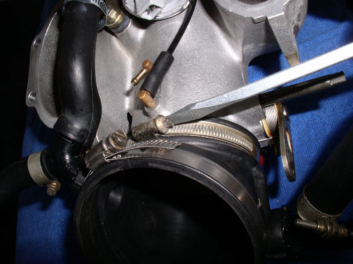
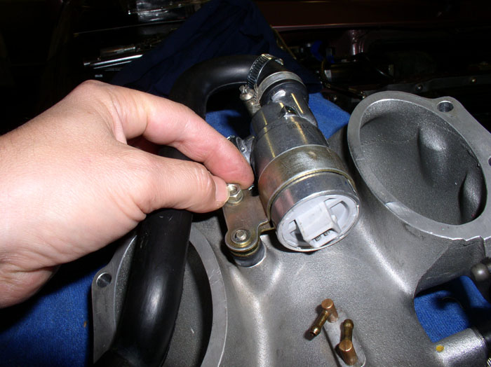
Next, remove the ISV from the throttle body. Begin by removing the two 10mm nuts that secure the ISV bracket to the throttle body.
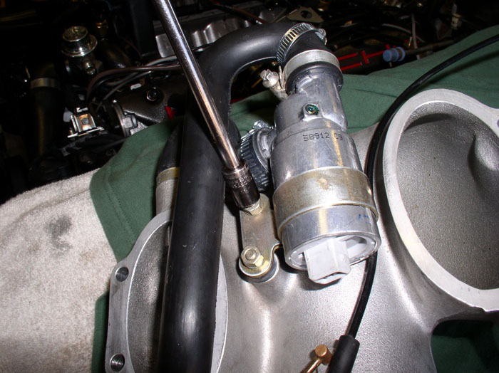
Then, loosen the clamp at the ISV supply hose at the throttle body. Disconnect the hose and remove the ISV and hoses attached.
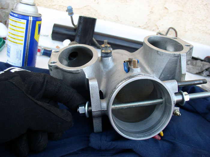
Now, remove the two vacuum hoses. The short vacuum line goes to the 7-port vacuum manifold at the rear of the engine. The long line goes to the fuel vent diaphram on the passenger fender wall by the coolant reservior. Short line goes on the rear port, long line on the front port.
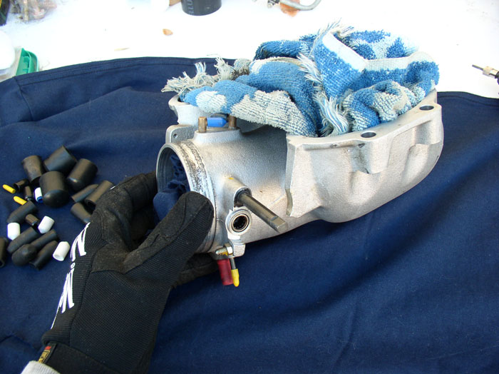
Stuff the throttle plate opening with a clean rag to minimize metal filings from getting into the throttle body.
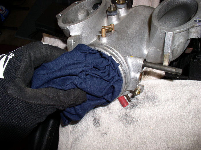
Stuff the intake ports on the throttle body with a clean towel for the same reasons. Cap the vacuum ports with vacuum plugs.
You can use a small pick tool to pick out the old shaft seal from the bearing housings. The linkage side seal was so thin, it didn't seem to be doing much good.
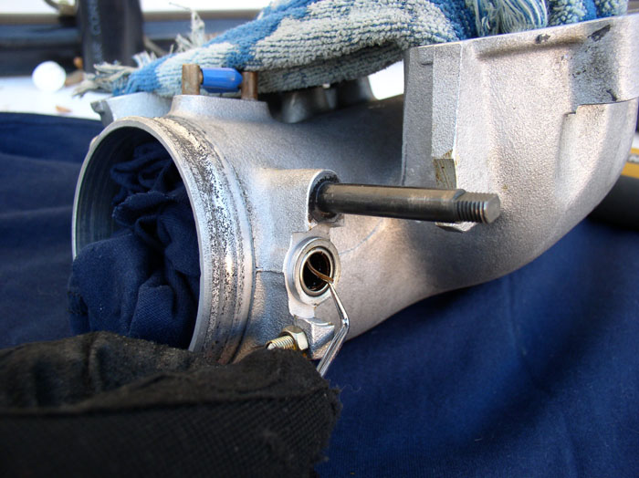
The TPS side shaft seal had disintegrated into small bits.
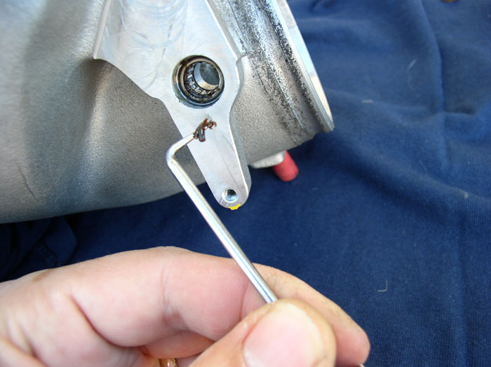
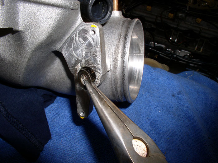
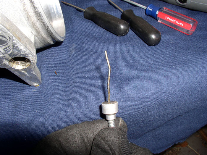
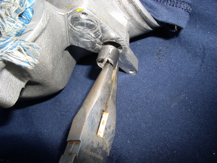
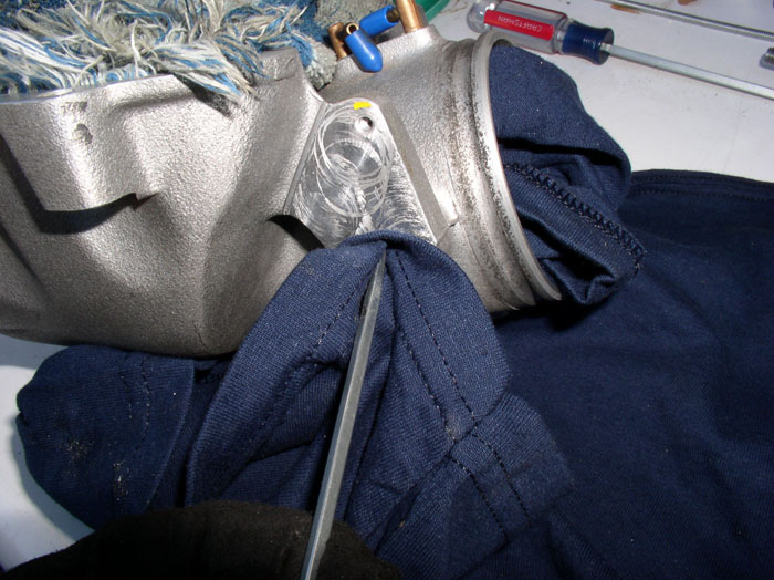
Use a flat blade screwdriver (thin blade) to pry up the needle bearing cage.
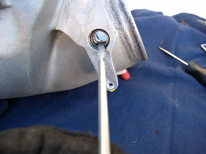
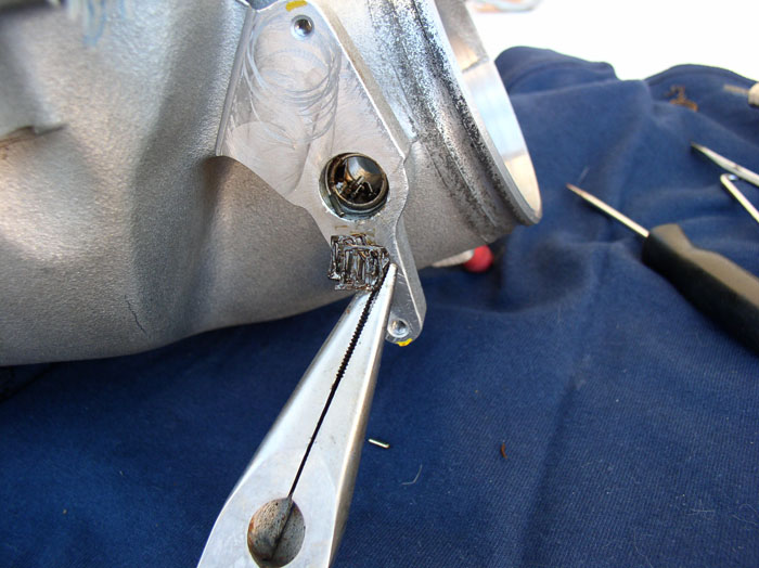
Then extract the needle bearing cage with a pair of needle nose pliers - how appropriate!
Now it's time to take a break and have some fun - you deserve it! Collect your needle bearings, grab your magnetic pick up tool and see how many needle bearings you can stack end to end. My record is 6!
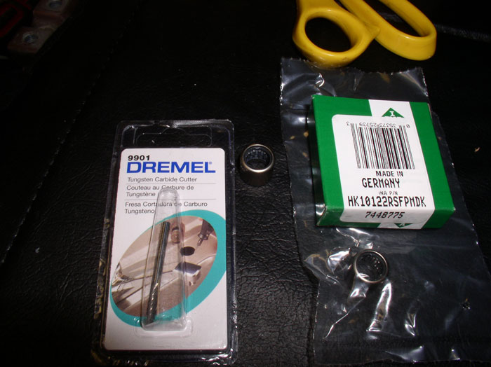
Now, back to work! We'll be using Schocki's favorite tool of choice for bearing cutting - the Dremel 9901 Tungsten Carbide Cutter! Also pictured are the double sealed bearings available from Roger - same bearings that fit the flappy valve shaft.
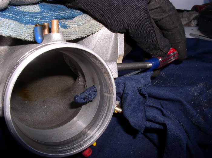
At this point, the bearing shell is all that is left to remove. Use the dremel with 9901 bit to cut through the bearing shell. It took me a little practice but after a few bearing removals, it's pretty easy. Insert the bit so that it hits the bottom (i.e., inside end) of the bearing casing and cut the full length of the bearing casing at the same time. Hold the bit level/parallel with the bearing casing so that you cut uniformly across the shell. It doesn't take long before you cut through the casing. If you're a newbie like me, use light pressure and remove the bit often while cutting to check your progress.
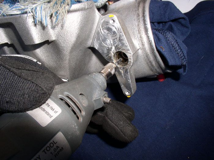
You will know you are close or done when you see the color of the metal casing change to a bright silver, that's the throttle body aluminum. Use light pressure on the dremel when you're getting close so as to minimize cutting into the aluminum of the bearing seat. On my latest bearing removals using this technique, the nick in the bearing seat is barely noticeable. Make sure you have a uniform strip of aluminum color down the length of the bearing casing. Then you can easily pry at the edges (near the cut) of the bearing casing with flat blade screwdriver to break the casing loose.
Then extract the cut casing with a pair of pliers.
Here's the old bearing casing next to the new bearing from Roger.
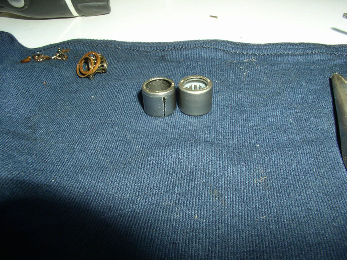
continued....
Then, loosen the clamp at the ISV supply hose at the throttle body. Disconnect the hose and remove the ISV and hoses attached.
Now, remove the two vacuum hoses. The short vacuum line goes to the 7-port vacuum manifold at the rear of the engine. The long line goes to the fuel vent diaphram on the passenger fender wall by the coolant reservior. Short line goes on the rear port, long line on the front port.
Stuff the throttle plate opening with a clean rag to minimize metal filings from getting into the throttle body.
Stuff the intake ports on the throttle body with a clean towel for the same reasons. Cap the vacuum ports with vacuum plugs.
You can use a small pick tool to pick out the old shaft seal from the bearing housings. The linkage side seal was so thin, it didn't seem to be doing much good.
The TPS side shaft seal had disintegrated into small bits.
Use a flat blade screwdriver (thin blade) to pry up the needle bearing cage.
Then extract the needle bearing cage with a pair of needle nose pliers - how appropriate!
Now it's time to take a break and have some fun - you deserve it! Collect your needle bearings, grab your magnetic pick up tool and see how many needle bearings you can stack end to end. My record is 6!
Now, back to work! We'll be using Schocki's favorite tool of choice for bearing cutting - the Dremel 9901 Tungsten Carbide Cutter! Also pictured are the double sealed bearings available from Roger - same bearings that fit the flappy valve shaft.
At this point, the bearing shell is all that is left to remove. Use the dremel with 9901 bit to cut through the bearing shell. It took me a little practice but after a few bearing removals, it's pretty easy. Insert the bit so that it hits the bottom (i.e., inside end) of the bearing casing and cut the full length of the bearing casing at the same time. Hold the bit level/parallel with the bearing casing so that you cut uniformly across the shell. It doesn't take long before you cut through the casing. If you're a newbie like me, use light pressure and remove the bit often while cutting to check your progress.
You will know you are close or done when you see the color of the metal casing change to a bright silver, that's the throttle body aluminum. Use light pressure on the dremel when you're getting close so as to minimize cutting into the aluminum of the bearing seat. On my latest bearing removals using this technique, the nick in the bearing seat is barely noticeable. Make sure you have a uniform strip of aluminum color down the length of the bearing casing. Then you can easily pry at the edges (near the cut) of the bearing casing with flat blade screwdriver to break the casing loose.
Then extract the cut casing with a pair of pliers.
Here's the old bearing casing next to the new bearing from Roger.
continued....
01-21-2009, 10:59 PM
#68
Archive Gatekeeper
Rennlist Member
Rennlist Member
When Roger introduced the double seal bearings I ordered 4, 'cause I just knew that Dwayne would figure out another place on the car to install the extra pair, yeah, that's it.... 
01-21-2009, 11:19 PM
#69
Rennlist Member
Thread Starter
Join Date: Sep 2007
Location: Ridgecrest, California
Posts: 1,363
Likes: 0
Received 143 Likes
on
28 Posts
After removing both bearings, use a clean rag to clean the metal filings from the bearing seats.
A screwdriver can help to stuff the rag through and sea-saw the rag in the seat to clean the filings out.
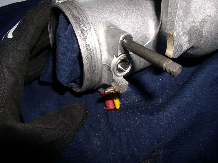
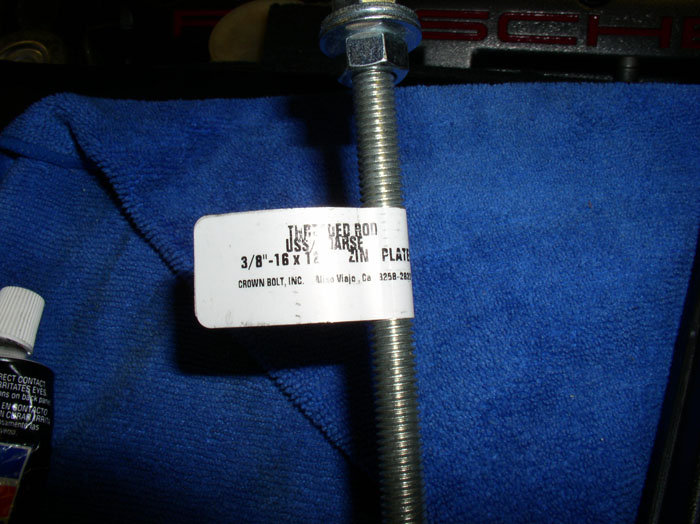
Here's a nice easy way to install the bearings. Got to Home Depot or your favorite hardware store and pick up a 3/8" threaded rod in a 12" length. Disregard the silicone sealant in the picture, you won't be using it here.
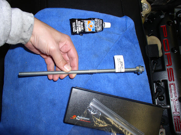
Also pick up two 3/8" nuts and 2 washers. I think I paid about $3 for all this. BTW, you will be able to use the exact same hardware to install the flappy valve bearings in the intake.
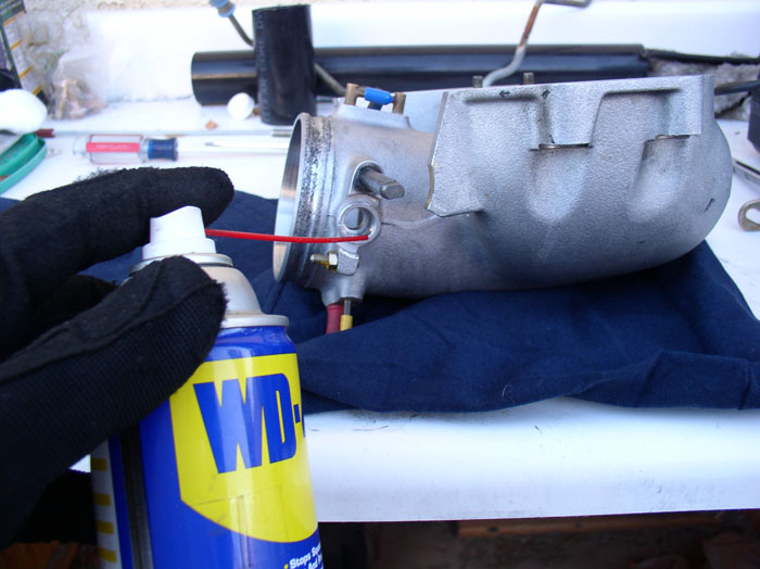
Then, use some WD-40 to lubricate the bearing seat.
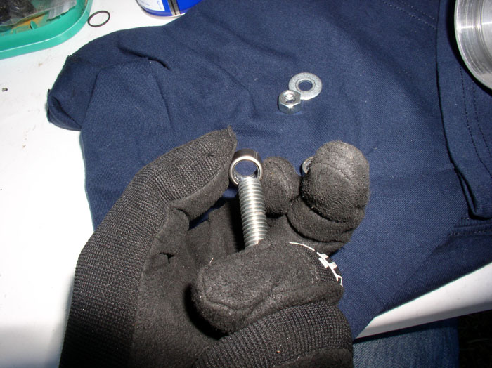
Place one nut and one washer on the threaded rod and then gently load one of the new bearings. Place the bearing on the rod so that the flat edge (bottom edge) of the bearing is facing the throttle body. The curved top edge of the bearing should be facing outward from the throttle body when fully seated. Be careful not to force the bearing on the threaded rod too hard as you may displace one of the seals.
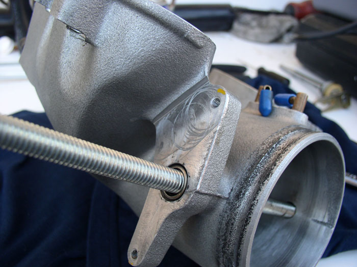
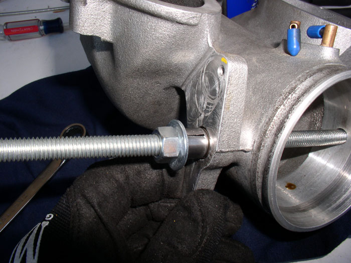
Next, slide the threaded rod throught the throttle body in the same manner as the plate shaft as shown below.
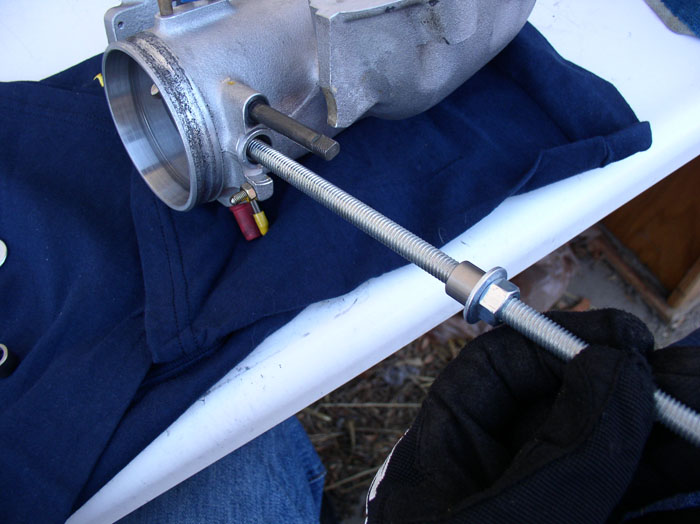
Attach the other washer and other nut to the threads on the other side of the threaded rod.
Use your choice of combination wrench or gear wrenchs on each nut to tighten down the bearing into the seat. The 3/8" rod fits well through the bearing and the bearing seats so that there is little opportunity for the bearing to get crosswise in the seat while tightening.
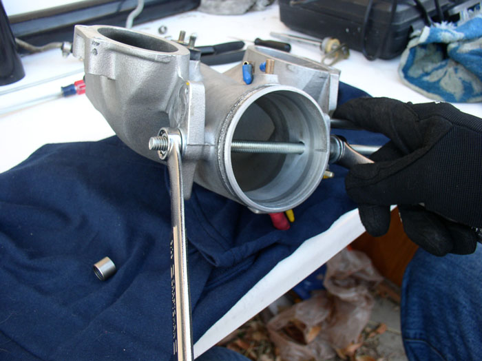
You should encounter little resistance while tightening the bearing into place.
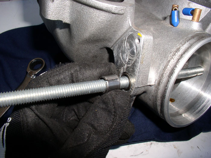
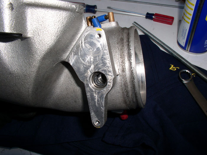
When you do encounter resistance, you have probably hit the bottom or seated the bearing flush against the throttle body. Stop tightening and take the nut and washer off. Then gently remove the threaded rod.
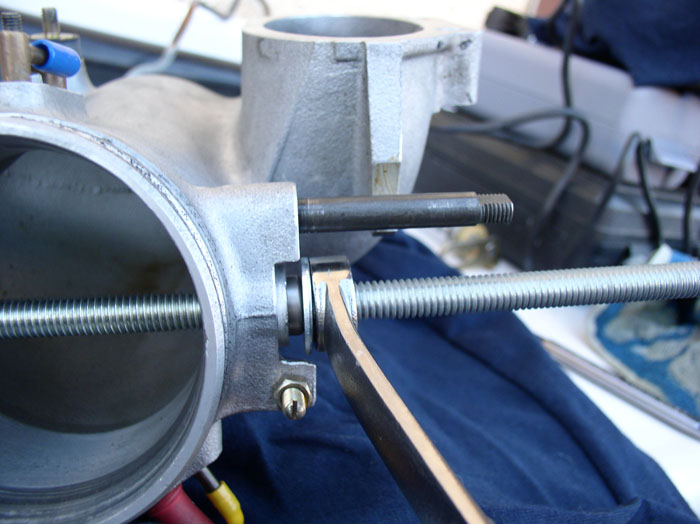
Next, set up the rod and bearing in the same manner for the TPS side of the throttle body. Tighten down the bearing...
...until it is flush with the throttle body. Remove the nut and washer but keep the threaded rod in place. As you recall, the TPS side bearing is recessed.
If you're old bearing casing you removed earlier is in good shape, load it onto the threaded rod....
...followed by the nut and washer.
continued.....
A screwdriver can help to stuff the rag through and sea-saw the rag in the seat to clean the filings out.
Here's a nice easy way to install the bearings. Got to Home Depot or your favorite hardware store and pick up a 3/8" threaded rod in a 12" length. Disregard the silicone sealant in the picture, you won't be using it here.
Also pick up two 3/8" nuts and 2 washers. I think I paid about $3 for all this. BTW, you will be able to use the exact same hardware to install the flappy valve bearings in the intake.
Then, use some WD-40 to lubricate the bearing seat.
Place one nut and one washer on the threaded rod and then gently load one of the new bearings. Place the bearing on the rod so that the flat edge (bottom edge) of the bearing is facing the throttle body. The curved top edge of the bearing should be facing outward from the throttle body when fully seated. Be careful not to force the bearing on the threaded rod too hard as you may displace one of the seals.
Next, slide the threaded rod throught the throttle body in the same manner as the plate shaft as shown below.
Attach the other washer and other nut to the threads on the other side of the threaded rod.
Use your choice of combination wrench or gear wrenchs on each nut to tighten down the bearing into the seat. The 3/8" rod fits well through the bearing and the bearing seats so that there is little opportunity for the bearing to get crosswise in the seat while tightening.
You should encounter little resistance while tightening the bearing into place.
When you do encounter resistance, you have probably hit the bottom or seated the bearing flush against the throttle body. Stop tightening and take the nut and washer off. Then gently remove the threaded rod.
Next, set up the rod and bearing in the same manner for the TPS side of the throttle body. Tighten down the bearing...
...until it is flush with the throttle body. Remove the nut and washer but keep the threaded rod in place. As you recall, the TPS side bearing is recessed.
If you're old bearing casing you removed earlier is in good shape, load it onto the threaded rod....
...followed by the nut and washer.
continued.....
01-22-2009, 12:05 AM
#70
Rennlist Member
Thread Starter
Join Date: Sep 2007
Location: Ridgecrest, California
Posts: 1,363
Likes: 0
Received 143 Likes
on
28 Posts
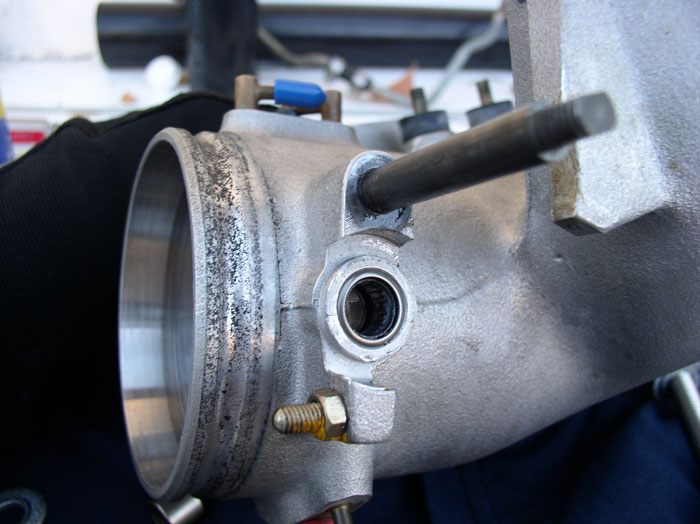
Tighten the nut down until you encounter resistance. Then remove the nut, washer and carefully remove the threaded rod. The bearing should be fully seated in the recessed cavity as shown.
Next, you install the throttle plate shaft. The bearing seals are already pre-lubricated but I used a small amount of silicone lubricant on the shaft itself to ease installation and not deform the bearing seals.
Insert the shaft on the spring linkage side as shown, being careful to keep an eye on the bearing seals - ensuring they do not bind or deform during installation of the shaft. Twisting the shaft on installation can help. I did have one seal bind on me while installing the shaft but by backing the shaft up and re-inserting with a twisting motion, the seal righted itself.
Install the throttle plate shaft until it is fully seated against the throttle body as shown.
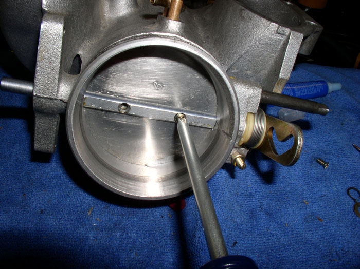
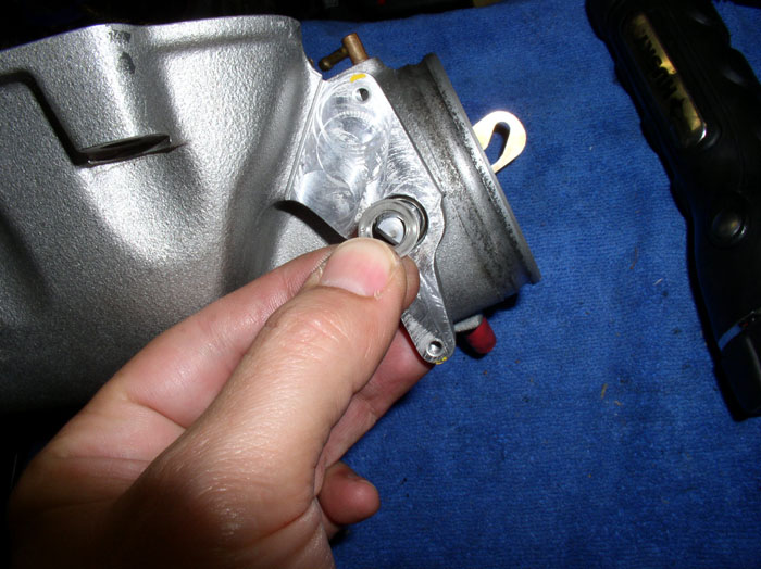
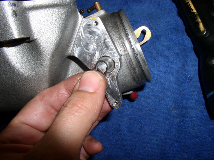
Next, install the throttle plate. You will notice a curved arc cut into the front surface of the throttle plate. This faces forward and on the bottom half of the shaft as shown.
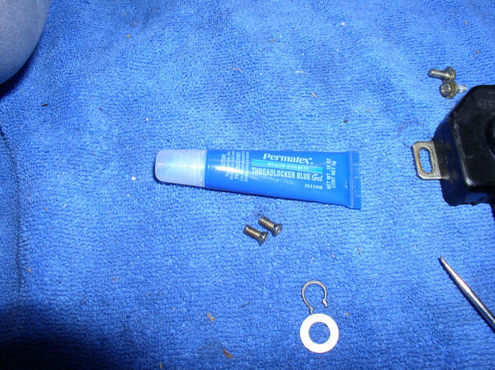
To ensure the throttle plate screws stayed put, I used threadlocker blue on the small phillips screw threads.
Install the plate by turning the throttle shaft 90 degrees and inserting the plate into the shaft. You will need to work the throttle shaft open and close until the throttle plate is positioned perfectly on the shaft so as not to scrape or rub on the sides of the throttle body walls. Once it's moving freely, tighten the plate down with the screws. Then operate the plate after the screws are tightened to ensure the plate still moves freely.
Then install the washer at the TPS side of the throttle plate shaft.
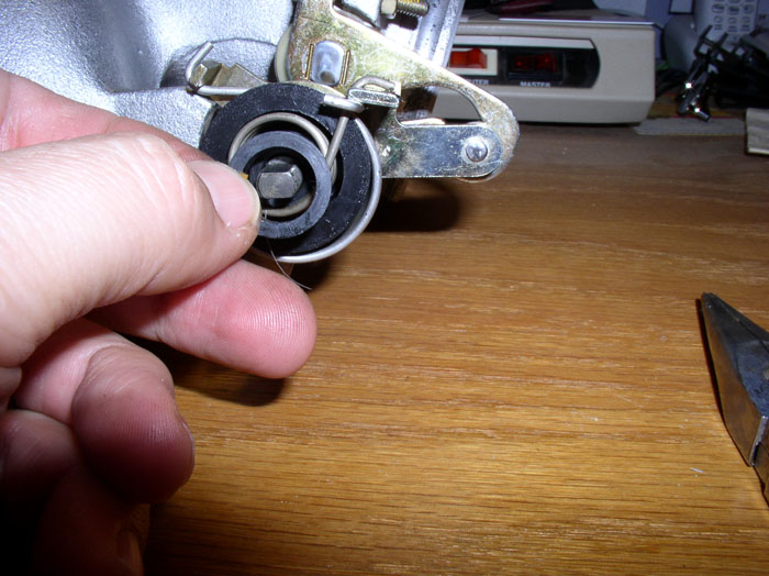
Followed by the small circlip. Use the circlip pliers once again to install the clip. If your clip was slightly stretched by the removal process, like mine. You can "clamp" it back into shape with some needle nose pliers after it's seated in the retaining groove of the throttle plate shaft.
Next, install the TPS. Position it approximately at the same orientation as you removed it. Lightly snug down the mounting screws. Then operate the throttle shaft and listen for the "click" of the idle contacts of the TPS as you move the shaft. Adjust the position of the TPS so that you hear the "click" when the throttle plate is open just about 1 degree. Then tighten down the mounting screws on the TPS. Test the operation again to ensure it's working as it did before the disassembly.
Now, install the 4 washers in the same order they come off the throttle cable linkage shaft (spring-flat-spring-flat).
I lightly lubricated the throttle cable linkage shaft with WD-40 during the intallation of the linkage. Next came the throttle cable lever arm.
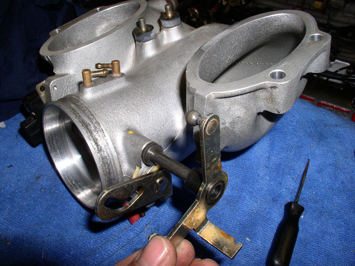
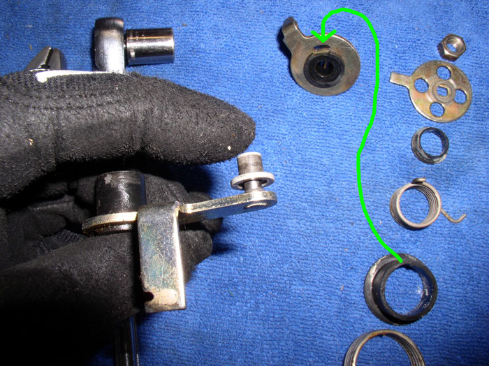
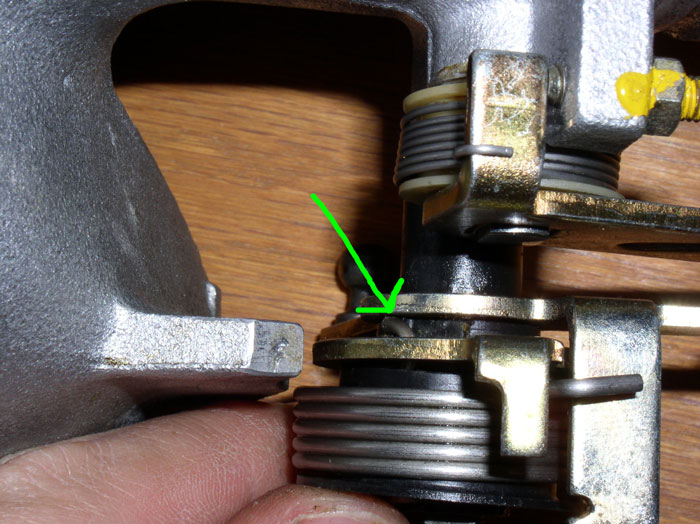
Next comes the outer and inner spring carrier. If your's is still intact, it will look like this below. The outer spring carrier (see green arrow), was broke on mine.
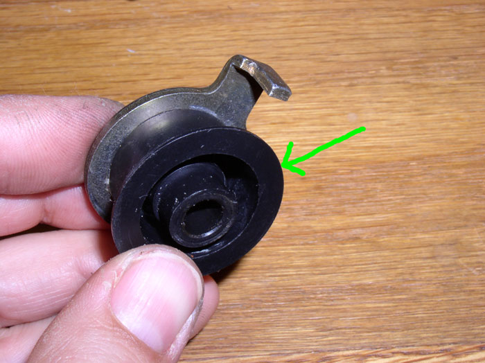
If yours is together, you can install the outer spring and position the unit back onto the shaft together as a unit as shown below.
Otherwise, locate the small notch on the outer spring carrier as indicated by the green arrow below.
continued.....
Next, you install the throttle plate shaft. The bearing seals are already pre-lubricated but I used a small amount of silicone lubricant on the shaft itself to ease installation and not deform the bearing seals.
Insert the shaft on the spring linkage side as shown, being careful to keep an eye on the bearing seals - ensuring they do not bind or deform during installation of the shaft. Twisting the shaft on installation can help. I did have one seal bind on me while installing the shaft but by backing the shaft up and re-inserting with a twisting motion, the seal righted itself.
Install the throttle plate shaft until it is fully seated against the throttle body as shown.
Next, install the throttle plate. You will notice a curved arc cut into the front surface of the throttle plate. This faces forward and on the bottom half of the shaft as shown.
To ensure the throttle plate screws stayed put, I used threadlocker blue on the small phillips screw threads.
Install the plate by turning the throttle shaft 90 degrees and inserting the plate into the shaft. You will need to work the throttle shaft open and close until the throttle plate is positioned perfectly on the shaft so as not to scrape or rub on the sides of the throttle body walls. Once it's moving freely, tighten the plate down with the screws. Then operate the plate after the screws are tightened to ensure the plate still moves freely.
Then install the washer at the TPS side of the throttle plate shaft.
Followed by the small circlip. Use the circlip pliers once again to install the clip. If your clip was slightly stretched by the removal process, like mine. You can "clamp" it back into shape with some needle nose pliers after it's seated in the retaining groove of the throttle plate shaft.
Next, install the TPS. Position it approximately at the same orientation as you removed it. Lightly snug down the mounting screws. Then operate the throttle shaft and listen for the "click" of the idle contacts of the TPS as you move the shaft. Adjust the position of the TPS so that you hear the "click" when the throttle plate is open just about 1 degree. Then tighten down the mounting screws on the TPS. Test the operation again to ensure it's working as it did before the disassembly.
Now, install the 4 washers in the same order they come off the throttle cable linkage shaft (spring-flat-spring-flat).
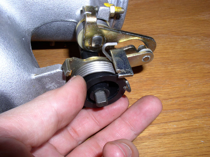
I lightly lubricated the throttle cable linkage shaft with WD-40 during the intallation of the linkage. Next came the throttle cable lever arm.
Next comes the outer and inner spring carrier. If your's is still intact, it will look like this below. The outer spring carrier (see green arrow), was broke on mine.
If yours is together, you can install the outer spring and position the unit back onto the shaft together as a unit as shown below.
Otherwise, locate the small notch on the outer spring carrier as indicated by the green arrow below.
continued.....
01-22-2009, 12:30 AM
#71
Rennlist Member
Thread Starter
Join Date: Sep 2007
Location: Ridgecrest, California
Posts: 1,363
Likes: 0
Received 143 Likes
on
28 Posts
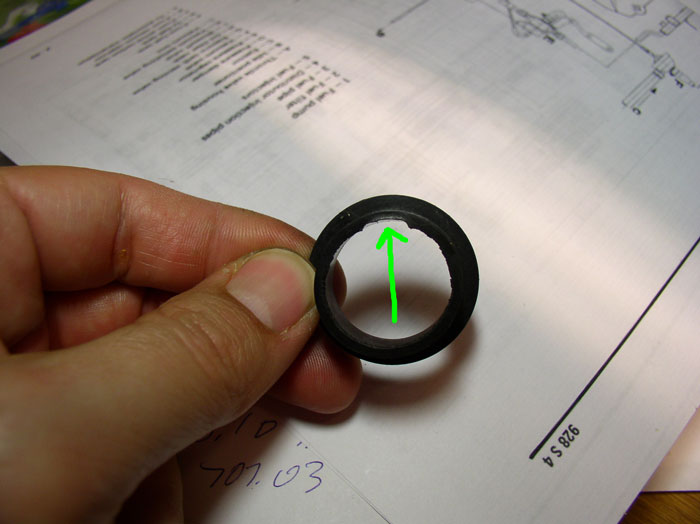
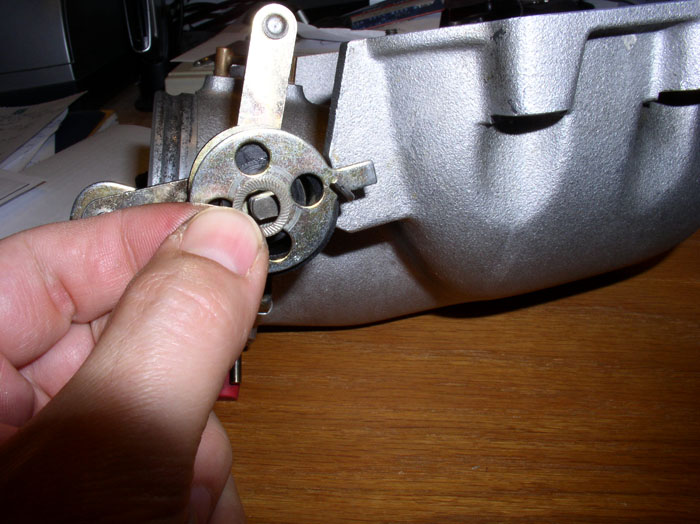
You will be aligning the notch in the plastic spring carrier with the oval slot in the spring carrier plate as shown with the green line. The notch in the plastic and oval in the plate are there to allow the inner spring to catch on the spring carrier plate (shown shortly). You could try to glue the plastic spring carrier back together with the plate using super glue or equivalent but I didn't think that would stand up to the pressure of the springs so I left them apart for the installation.
First, install the spring carrier plate followed by the outer spring as shown.
Then, install the spring carrier lining up the notch with the oval slot on the plate as described two pictures ago.
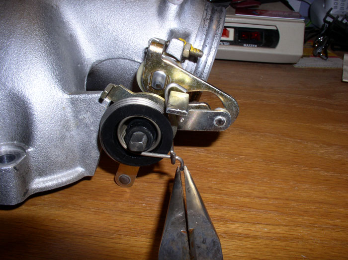
Next, install the inner spring as shown.....
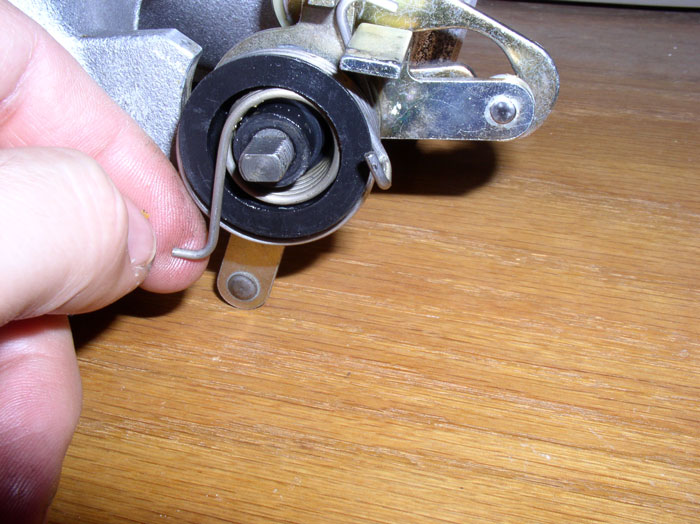
and hook the other end of the inner spring on the carrier plate as shown below.
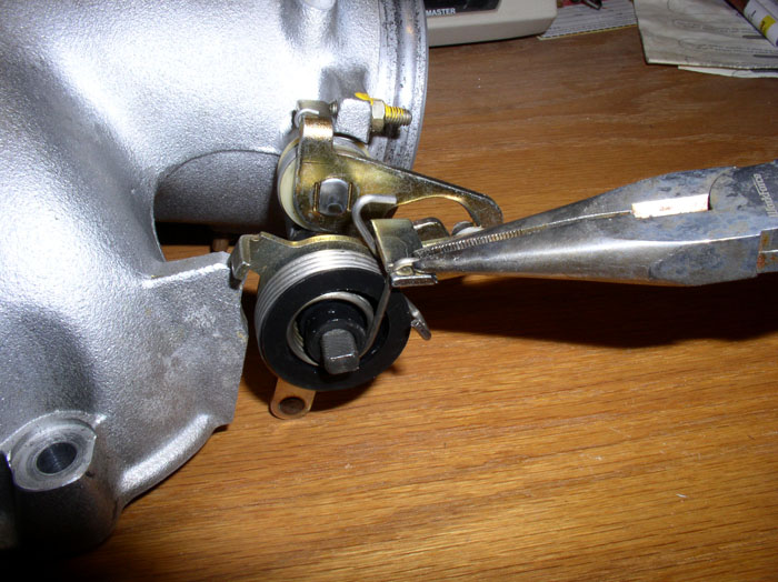
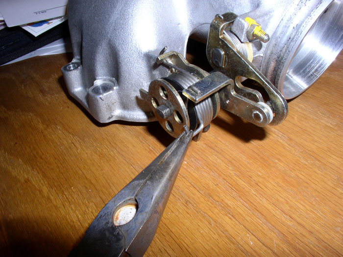
Then grasp the other end of the inner spring with pliers.....
....and secure it in the notch on the catch as pictured below.
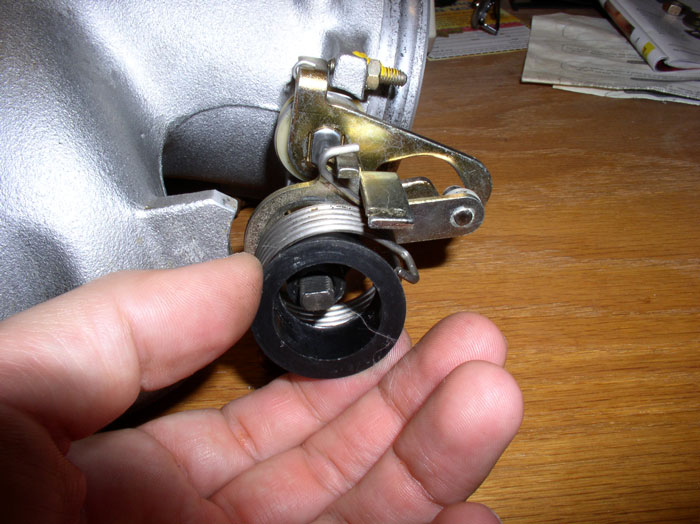
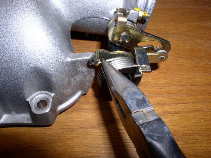
Grasp the outer spring with pliers and secure the end on the catch as shown below.
Place the small plastic retaining washer on the shaft next.
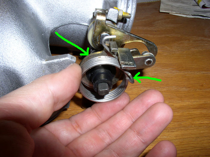
Install the outer catch plate as shown and grasp the other end of the outer spring with pliers and .....
attach the spring to the catch on the outer plate as shown.
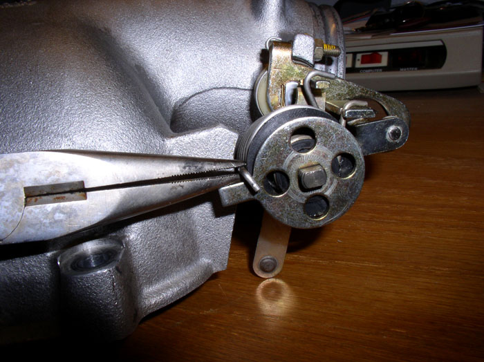
Install the ribbed washer.
Followed by the 13mm nut. Tighten down the 13mm nut to secure the assembly. Operate the throttle linkage and plate. It should be smooth and have about the same resistance as before you disassembled it.
Next, install the ISV by secruring the mounting bracket to the throttle body with the two 10mm nuts.
Reattach the ISV hose to throttle body intake and tighten the clamp.
continued......
First, install the spring carrier plate followed by the outer spring as shown.
Then, install the spring carrier lining up the notch with the oval slot on the plate as described two pictures ago.
Next, install the inner spring as shown.....
and hook the other end of the inner spring on the carrier plate as shown below.
Then grasp the other end of the inner spring with pliers.....
....and secure it in the notch on the catch as pictured below.
Grasp the outer spring with pliers and secure the end on the catch as shown below.
Place the small plastic retaining washer on the shaft next.
Install the outer catch plate as shown and grasp the other end of the outer spring with pliers and .....
attach the spring to the catch on the outer plate as shown.
Install the ribbed washer.
Followed by the 13mm nut. Tighten down the 13mm nut to secure the assembly. Operate the throttle linkage and plate. It should be smooth and have about the same resistance as before you disassembled it.
Next, install the ISV by secruring the mounting bracket to the throttle body with the two 10mm nuts.
Reattach the ISV hose to throttle body intake and tighten the clamp.
continued......
01-22-2009, 12:49 AM
#72
Rennlist Member
Thread Starter
Join Date: Sep 2007
Location: Ridgecrest, California
Posts: 1,363
Likes: 0
Received 143 Likes
on
28 Posts
Install the Air Guide Cowl but don't tighten the clamp yet.
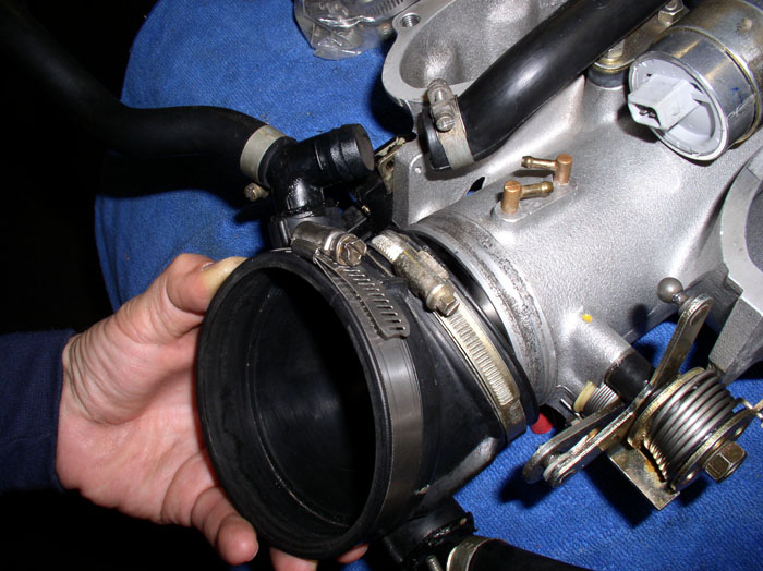
Attach the ISV supply hose to the Air Guide Cowl as shown and tighten the clamp.
Now, tighten the clamp on the Air Guide Cowl ensuring it is lined up properly. I lined up the center ridge on top of the cowl with the two vacuum ports.
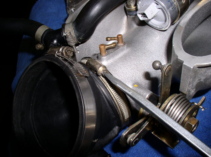
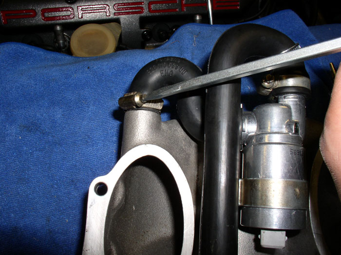
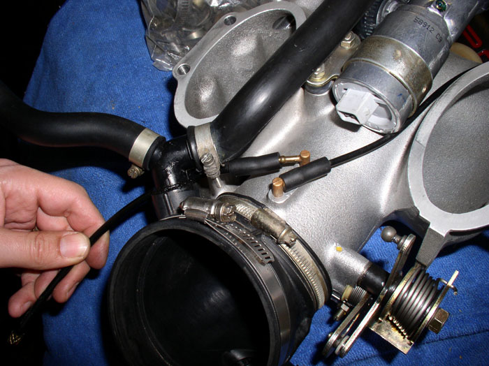
Attach the vacuum lines to the vacuum ports. Short line to the rear port and long line to the front port as shown.
Re-attach the throttle body to the intake using the four 13mm bolts. Torque to 15 ftlbs.
Congratulations! Your vacuum leak at the throttle body linkage should be cured!
As mentioned before, I fixed this leak AFTER I had assembed the intake and had to take it off again. I should have tested the throttle body for leaks before taking the intake off the car and then I would be fixing the leak while the intake was at the powder coaters. So, now we'll resume the intake installation procedure.
continued.......
Attach the ISV supply hose to the Air Guide Cowl as shown and tighten the clamp.
Now, tighten the clamp on the Air Guide Cowl ensuring it is lined up properly. I lined up the center ridge on top of the cowl with the two vacuum ports.
Attach the vacuum lines to the vacuum ports. Short line to the rear port and long line to the front port as shown.
Re-attach the throttle body to the intake using the four 13mm bolts. Torque to 15 ftlbs.
Congratulations! Your vacuum leak at the throttle body linkage should be cured!
As mentioned before, I fixed this leak AFTER I had assembed the intake and had to take it off again. I should have tested the throttle body for leaks before taking the intake off the car and then I would be fixing the leak while the intake was at the powder coaters. So, now we'll resume the intake installation procedure.
continued.......
01-22-2009, 01:17 AM
#74
Rennlist Member
Thread Starter
Join Date: Sep 2007
Location: Ridgecrest, California
Posts: 1,363
Likes: 0
Received 143 Likes
on
28 Posts
HA! We think alike....I ordered extra as well not knowing what I'd use them for (other than flappy repair) or when I'd use them. Now I know!
01-22-2009, 01:24 AM
#75
Rennlist Member
Thread Starter
Join Date: Sep 2007
Location: Ridgecrest, California
Posts: 1,363
Likes: 0
Received 143 Likes
on
28 Posts
I've got some 928 repairs to do this weekend - Timing Belt Tension adjustment on Virginia, coolant leak on Idaho and several items on California that deserve attention. I'm going to try to make it down there anyway - thanks for the heads up!