Torque tube rebuild pictures and tools
 10-09-2005, 06:11 PM
#46
Addict
Rennlist Member
Rennlist Member
Thread Starter
Originally Posted by Peter F
do you also have the location of the vibration damper?
Recently heard about one 4sp automatic TT where damper was directly after 3rd bearing.
 03-07-2006, 05:55 PM
#47
Addict
Rennlist Member
Rennlist Member
Thread Starter
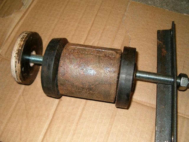
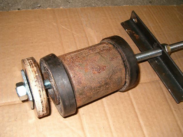
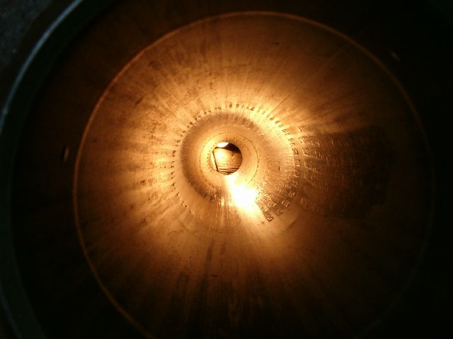
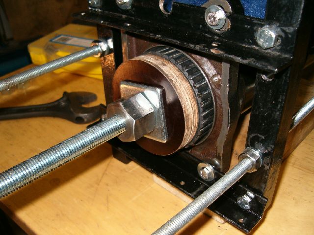
Finally some progress again. Vibration damper is out at last. Since there wasn't anything else left it we could use better support made of wood than flat iron at end of threaded rod to pull it out. It was positioned about 94 cm from the front and 34 from rear. Damper lenght is 13.5 cm.
New bearings came from local bearing supply store. We tried to find C5 but had to settle for C4 with high temperature grease. Even those were not available unless one bought at least 20 at a time. Perfect opportunity to have group buy on them. Ended up geting 30 while at it. All of them are now on hands of local 928 owners.
We have started on putting '78 shaft back together. Bearings were pressed into carriers in a vise with aluminum pieces available from local tool store.

Black center thing was pressed in to bearing using same aluminum pieces and normal sockets. To make sure piece do not have possibility to get out of bearing inner race we made pressing tool from 4mm thick flat steel bar. It was used to bent metal towards outside in a vise.
Center bearing was pressed in from rear even though it would have been shorter distance from the front. Idea behind this is that it is easier to push against flat rear surface that grooved front side. Also at front of TT outer tube there is hole for clamp bolt mounting. Hole will probably make pushing front bearing support little more difficult when we have time to do it.
New bearings came from local bearing supply store. We tried to find C5 but had to settle for C4 with high temperature grease. Even those were not available unless one bought at least 20 at a time. Perfect opportunity to have group buy on them. Ended up geting 30 while at it. All of them are now on hands of local 928 owners.
We have started on putting '78 shaft back together. Bearings were pressed into carriers in a vise with aluminum pieces available from local tool store.
Black center thing was pressed in to bearing using same aluminum pieces and normal sockets. To make sure piece do not have possibility to get out of bearing inner race we made pressing tool from 4mm thick flat steel bar. It was used to bent metal towards outside in a vise.
Center bearing was pressed in from rear even though it would have been shorter distance from the front. Idea behind this is that it is easier to push against flat rear surface that grooved front side. Also at front of TT outer tube there is hole for clamp bolt mounting. Hole will probably make pushing front bearing support little more difficult when we have time to do it.
03-07-2006, 10:06 PM
#49
Rennlist Member

Tony wrote:
"Gotta love it!
looks like your loading an artillery shell into a 105mm!"
I dunno. 105's don't use ramming rods, gotta get a bit bigger for that. ;-)
Redleg Will
BTW - TY, TY, TY for this thread, Erkka.
"Gotta love it!
looks like your loading an artillery shell into a 105mm!"
I dunno. 105's don't use ramming rods, gotta get a bit bigger for that. ;-)
Redleg Will
BTW - TY, TY, TY for this thread, Erkka.
03-18-2006, 07:03 PM
#50
Addict
Rennlist Member
Rennlist Member
Thread Starter
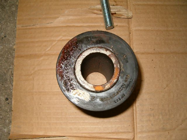
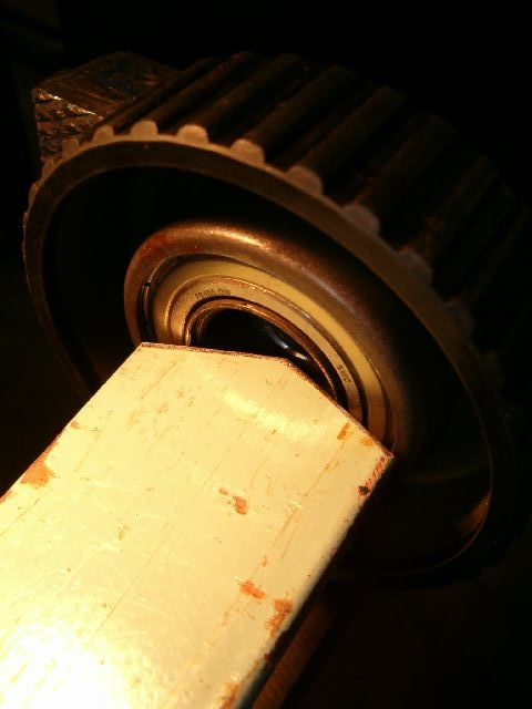
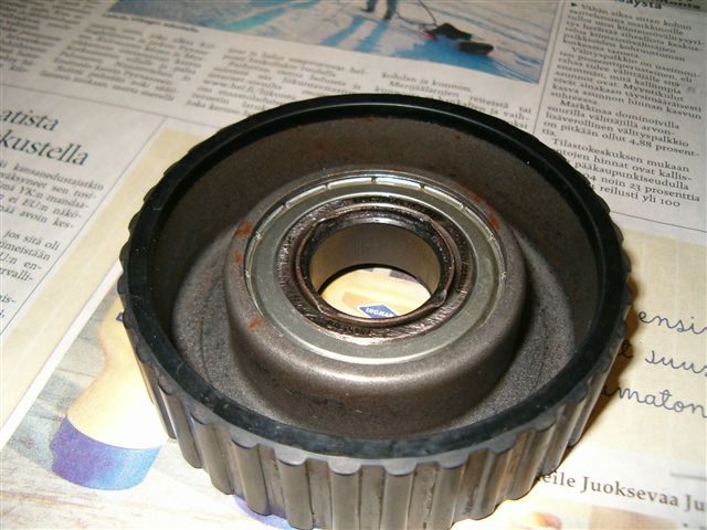
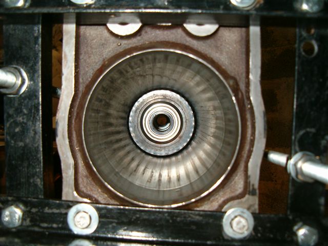
Here's picture how bearing center thing looks like after metal has been bent in vice with flat iron shown at previous post. Those four pressings on the perimeter should make sure center don't get out from bearing.
We are worried about bearing support moving inside tube. AFAIK this isn't unusual occurrence. To make sure they can't do it we put 70mm diameter plastic sewer pipes between bearing supports. At both ends of each pipe there is rubber band to make them stick to tube walls and prevent moving. Once all is in there's no place for bearing supports to go. Nothing can move except center shaft if it slides back or forth. Gearbox input shaft clamp should keep it from moving. This is complex solution I know. Since time isn't big problem for us we can do things stupid way. If I were doing this as business I would drain in some suitable glue into TT tube to hold carriers in place and be done with it.
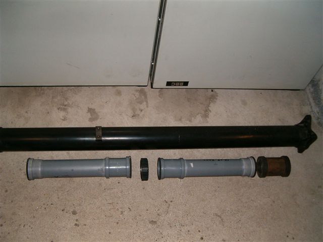
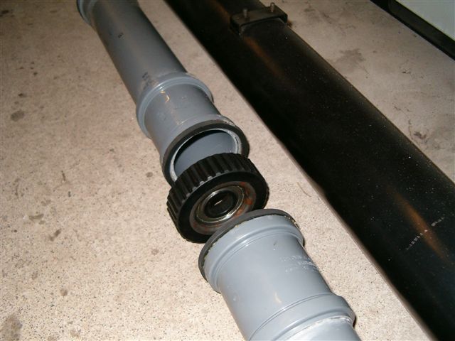
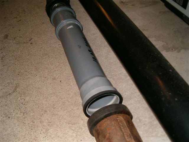
Second pipe between bearing carrier and vibration damper is way too long for that position. Added first two ready pipes into pic just to give idea how all stack up inside tube. When in TT there will not be any gaps between parts of course.
One pipe is already inside '78 TT as are 2nd and 3rd bearing. We hope to get '78 on road few months from now.
We are worried about bearing support moving inside tube. AFAIK this isn't unusual occurrence. To make sure they can't do it we put 70mm diameter plastic sewer pipes between bearing supports. At both ends of each pipe there is rubber band to make them stick to tube walls and prevent moving. Once all is in there's no place for bearing supports to go. Nothing can move except center shaft if it slides back or forth. Gearbox input shaft clamp should keep it from moving. This is complex solution I know. Since time isn't big problem for us we can do things stupid way. If I were doing this as business I would drain in some suitable glue into TT tube to hold carriers in place and be done with it.
Second pipe between bearing carrier and vibration damper is way too long for that position. Added first two ready pipes into pic just to give idea how all stack up inside tube. When in TT there will not be any gaps between parts of course.
One pipe is already inside '78 TT as are 2nd and 3rd bearing. We hope to get '78 on road few months from now.
03-19-2006, 11:38 AM
#51
Rennlist Member
Vilhuer wrote:
"... We are worried about bearing support moving inside tube. AFAIK this isn't unusual occurrence. To make sure they can't do it we put 70mm diameter plastic sewer pipes between bearing supports. ...
Would it also work to "pin" the bearing supports? I can think of two ways. Drill through the TT and into the bearing support and use a sheet metal screw anchor, or maybe drill and tap all the way through the bearing supprt and use machine bolts, fixing the carrier in place.
Or drill and tap in front and back of the carriers and use machine bolts to disallow migration in either direction.
And finally, is there any kind of "shoulder" where the TT mounts at each end? If so, then the plastic pipes could be cut to butt up against those shoulders and mechanically locate the carriers and damper.
Comments anyone?
03-19-2006, 03:55 PM
#52
Addict
Rennlist Member
Rennlist Member
Thread Starter
Originally Posted by Fogey1
Would it also work to "pin" the bearing supports? I can think of two ways. Drill through the TT and into the bearing support and use a sheet metal screw anchor, or maybe drill and tap all the way through the bearing supprt and use machine bolts, fixing the carrier in place.
And finally, is there any kind of "shoulder" where the TT mounts at each end? If so, then the plastic pipes could be cut to butt up against those shoulders and mechanically locate the carriers and damper.
I've been thinking about making rings out of steel or aluminum and bolting them in place to hold front and back ends. Locking in place done either from inside towards out with suitable hard end screws which will go into tube walls a little without drilling holes to it or perhaps easier solution of drilling holes from outside in and bolting ring from outside. '78 tube is most likely put together without front and rear support. I wouldn't do it but it's not my car so I'm not one making the decision.
05-22-2006, 07:19 AM
#53
Addict
Rennlist Member
Rennlist Member
Hi Erkka
Have you put the TT bearings back in the TT yet, and if you how diid you do it?
I ask because Eric and I are in the process of putting the new bearings back into the the TT from his 84 here in NZ. We decided we'ld but the bearings with the internal plastic sleeves and their carriers into the tube then put the drive shaft through the bearings in the direction that wouldn't push the internal sleeves out. This worked OK for the first bearing but it pushed the bearing out of the carrier for the middle bearing.
Tommorow we will remove the middle and front bearing and intend to put the middle bearing back on the shaft then inserting the sahft and bearing using an 80mm diameter tube while supporting the rear bearing from the rear. Then we will insert the front bearing.
It would be nice to have pictures but we were kind of busy!
This is a follow on to the will the 89 tranny fit the 84 - we think so but we'll see.
05-22-2006, 12:21 PM
#54
Addict
Rennlist Member
Rennlist Member
Thread Starter
Hi Jon
We have '78 TT ready now. We also had some problems in pushing center shaft through middle and front bearings. Shaft was tight fit and started to push bearing support forward once we hit end of narrow front portion. It could not push bearing out from carrier as carrier was positioned so that direction where bearing can come out was on side where shaft was entering in. This should guarantee carrier, bearing and internal sleeve can not separate from each other.
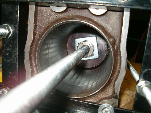
At first we put center and rear bearings plus plastic pipe between them into TT tube. Then we pushed center shaft in from rear up to a point where it's front end was close to a position where front bearing needs to be. As front bearing was not in yet it was easier to see what's going on at center bearing. While pushing shaft in we had pipe inside TT supporting center bearing supports front side. Support pipe was held in position by plate and clamps at front end of TT tube. Since center bearing support could not move forward it also held rear bearing support in correct position through intermediate plastic pipe. Without pipe in between I can easily imagine rear bearing support moving with center shaft even though center support is held in place.
Once center shaft was through center bearing and close to where front bearing would be we pushed plastic pipe and front one in. After this we again installed pipe support at front of the tube and proceeded pushing shaft forward until it was in correct position. Last job was to put in 3cm wide donuts at front and rear ends of bearing-pipe-bearing-pipe-bearing chain. These were made from 10cm wide solid nylon bar and pushed in with pipe. In their center there is 45mm large hole for center shaft to go through. Both donuts were mounted to TT tube by drilling three holes through from outside. Drillings are not all the way through to keep shavings from entering inside TT while we were drilling and to make sure donuts are as strong as possible. We didn't want to use metal in this application as it might rust on to TT and be very difficult to take out. After making holes we made threads to both TT and nylon and mounted bolts to keep them from moving. There is also few mm thick rubber ring between nylon and bearing support. This together with rubbers at ends of plastic pipes allow some slight movement for bearing support to cever for differnt heat expansion rates etc.
Normal TT design has only glue if even that for holding bearing supports in place. We now have support from both sides for all three bearing supports. Internal sleeve should stay in it's place when metal is bend. Only somewhat weak link is how bearing stays in support and even this should not be a problem since there is small drop of glue there. This kind of complex solution is overkill really but good thing in it is it should make 110% sure everything stays where they should. I have some more pics but can't upload them yet.
I think you shouldn't have any problems in fitting '89 tranny into '84, if they are manual gearboxes that is. Automatic TT should also work fine but gearbox will not fit into body without some modification to make more room for torque converter I believe.
We have '78 TT ready now. We also had some problems in pushing center shaft through middle and front bearings. Shaft was tight fit and started to push bearing support forward once we hit end of narrow front portion. It could not push bearing out from carrier as carrier was positioned so that direction where bearing can come out was on side where shaft was entering in. This should guarantee carrier, bearing and internal sleeve can not separate from each other.
At first we put center and rear bearings plus plastic pipe between them into TT tube. Then we pushed center shaft in from rear up to a point where it's front end was close to a position where front bearing needs to be. As front bearing was not in yet it was easier to see what's going on at center bearing. While pushing shaft in we had pipe inside TT supporting center bearing supports front side. Support pipe was held in position by plate and clamps at front end of TT tube. Since center bearing support could not move forward it also held rear bearing support in correct position through intermediate plastic pipe. Without pipe in between I can easily imagine rear bearing support moving with center shaft even though center support is held in place.
Once center shaft was through center bearing and close to where front bearing would be we pushed plastic pipe and front one in. After this we again installed pipe support at front of the tube and proceeded pushing shaft forward until it was in correct position. Last job was to put in 3cm wide donuts at front and rear ends of bearing-pipe-bearing-pipe-bearing chain. These were made from 10cm wide solid nylon bar and pushed in with pipe. In their center there is 45mm large hole for center shaft to go through. Both donuts were mounted to TT tube by drilling three holes through from outside. Drillings are not all the way through to keep shavings from entering inside TT while we were drilling and to make sure donuts are as strong as possible. We didn't want to use metal in this application as it might rust on to TT and be very difficult to take out. After making holes we made threads to both TT and nylon and mounted bolts to keep them from moving. There is also few mm thick rubber ring between nylon and bearing support. This together with rubbers at ends of plastic pipes allow some slight movement for bearing support to cever for differnt heat expansion rates etc.
Normal TT design has only glue if even that for holding bearing supports in place. We now have support from both sides for all three bearing supports. Internal sleeve should stay in it's place when metal is bend. Only somewhat weak link is how bearing stays in support and even this should not be a problem since there is small drop of glue there. This kind of complex solution is overkill really but good thing in it is it should make 110% sure everything stays where they should. I have some more pics but can't upload them yet.
I think you shouldn't have any problems in fitting '89 tranny into '84, if they are manual gearboxes that is. Automatic TT should also work fine but gearbox will not fit into body without some modification to make more room for torque converter I believe.
05-22-2006, 12:53 PM
#55
928 Collector
Rennlist Member
Rennlist Member
Erkka, with holes drilled for pinning, maybe easier because you can not just pin the bearing but also you can position it exactly where it should be, as well as, you can see through the hole when the bearing is in position ... right? Looks like a LOT of hard work.
05-22-2006, 01:56 PM
#56
Addict
Rennlist Member
Rennlist Member
How does the vibration damper work? What does it do? Is it possible for it to come loose and slide back and forth like a slide hammer? Maybe this is the source of my '87 elusive inertial "clunk" when I take off or stop quickly. Also there is an occasional "jingling" sound in that vicinity, like something loose on the dive shaft. Great thread - very enlightening.
05-22-2006, 02:15 PM
#57
Addict
Rennlist Member
Rennlist Member
Thread Starter
H, holes where drilled only after everything was in already and they are not all the way through nylon. If nylon is taken out then it would be possible to see where front and rear bearings are.
06-01-2006, 07:08 PM
#58
Addict
Rennlist Member
Rennlist Member
I now have started my TT renovation,
tube on the ground and center shaft driven out to the rear most bearing.
Checked the shaft for roundness at the front of the TT while rotating the shaft.
There is a shift of around 1 mm when turning half a lap.
Would this be of any value with the current shaft position?
Do I need a new TT or should I proceed with the renovation?

Thanks/Peter
tube on the ground and center shaft driven out to the rear most bearing.
Checked the shaft for roundness at the front of the TT while rotating the shaft.
There is a shift of around 1 mm when turning half a lap.
Would this be of any value with the current shaft position?
Do I need a new TT or should I proceed with the renovation?
Thanks/Peter
06-02-2006, 12:16 AM
#59
Addict
Rennlist Member
Rennlist Member
Peter
I recall that when we did Erics TT here in NZ last week the shaft didn't seem perfectly straight (It wobbled when it was half out of the tube)
When you have the shaft out place it on a flat surface (OK very flat surface) - A slate bed snooker table would be ideal - and roll the shaft along - you should be able to see any lack of straightness.
I bet what you are seeing is worn bearings. allowing the shaft to move about as you rotate it.
Good luck with the rest of the TT job.
Cheers