When you click on links to various merchants on this site and make a purchase, this can result in this site earning a commission. Affiliate programs and affiliations include, but are not limited to, the eBay Partner Network.
I posted a lot of this development in Hans' Intake thread, but have decided to start a separate thread about it. Although I am not jumping right back in on it - - still hung up on the welding aspect of it - - but I am doing some further research about some aspects of it in the meantime.
I obtained Hans' intake bases for the sole purpose of developing an intake with a lower profile than the S4 intake for use in my not-yet-started Radical Custom 928. Since I am going to section the car the hood will end up 2 inches lower than stock, so the intake needs to be about that much lower to fit under it without some kind of hood modification, which I do not want.
The progress I have made on my manifold design is still hung up on my somewhat limited aluminum welding skills, and while I'm working on that I have also been looking kind of backwards at some of the criteria that I pretty much gave little or no thought to when I started, such as any basic manifold design criteria and sucn as considerations about air pressure differentials and any need to consider those in the design.
Some research suggests that longer intake tubes, such as I think I have incorporated, are better for low end, and that a smaller intake plenum, which I think I also have, is also better for lower end performance. I think my design probably fits pretty well where I would intend to use this car.
Other thoughts, raised in the other thread, have to do with flex in the manifold, or more specifically the sheet metal plenum, and I am having some second thoughts about some of the material that I have been planning to incorporate here. I don't think any of that will change the design, but while I am at the point of further fabrication, and even replacing some of what I have made so far, I am going to consider heavier material. More about that when I actually get back to this.
These pictures don't really show much progress, but they might be helpful to put this new thread in perspective.
I do have the hole patterns for both sides worked out and when I make a final decision on the weight of aluminum for the sides I can transfer the patterns and cut the holes.
I have some rubber elbows for the MAF connection, but I am thinking that I'm going to connect it straight back rather than at an upward angle. I think that might give me a better presentation to whatever new design of lower filter/air box I am going to need to design and fabricate for this intake.
I still haven't decided just how best to make the "fairings" for the two intake holes in the bottom of this plenum, since they are somewhat outside of the bottom outer edges of the plenum base as currently designed. The choices I think are to lean them in, lean them out (a little bit anyway) or have them point straight up. I'm thinking that when I have the actual sides cut with the tube openings the solution is going to kind of present itself.
I put one of the patterns to works on the passenger side of the plenum and milled then filed the four holes for the tubes. This is still using the original .063 6061 T651 aluminum that I started with, and I may still stay with it. If I find that I need to do this over I'll probably use heavier material. Sometimes a fabricated component becomes a pattern for the next one, and so forth until I get it right.
One of the difficulties in configuring this intake without any welding, at least until I get to the welding point, is that the short flanged recess in Hans' intake bases is so shallow that it is hard to get the tubes to fit and stay or hold with friction only while I'm fitting other pieces. I had suggested to Hans that in the next ones he might make of these he ought to make the flanged recess in the tops a little deeper. He didn't think that would be a good idea. And I respect that, since it is his design.
However, I think I am going to make a 22.5 degree base to bolt these bases to and then mount them in my rotary table in my mill and recess each of the openings so they will be a bit deeper, probably only about .100" to .125" more so that the bases will have a better grip on the tubes before they get welded. It looks like there is enough material to do that without any problem. Otherwise I almost need three or four hands to hold everything together for all this fitting. I don't think the extra depth will cause any significant problem in what I have done so far in regard to the lengths of the tubes, except maybe a tiny bit with the front two tubes.
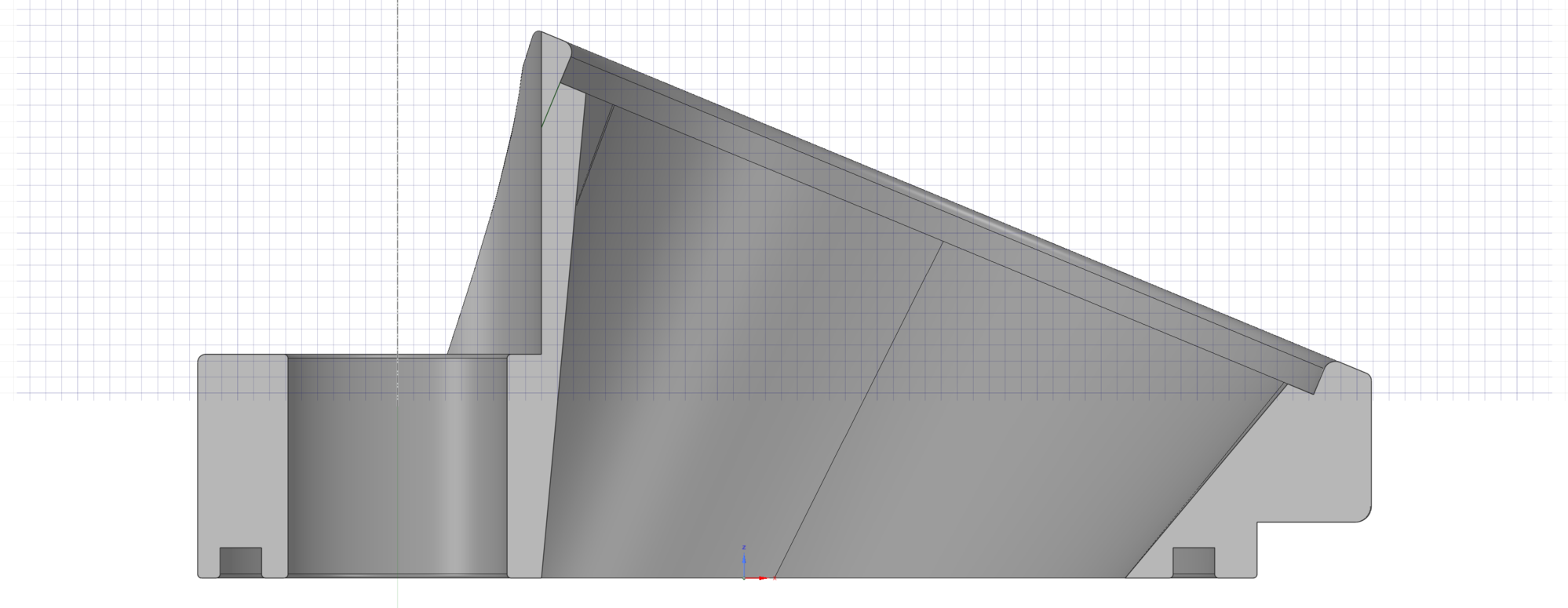
FYI, that small green line on the cross-section is 3.042mm, so if you increase the depth of that bore, just be mindful you dont increase it too much and breach through to the injector bore.
One thing that you cannot tell from the pictures is that there are a few different ways to configure the tubes inside the plenum. One thing you can see is that the bell mouth of each tube rests next to or in between and near the base of the tubes on the other side. The space between the tubes where the bell mouths reside gets a little narrower as you move back in the plenum, for some reason I'm not sure I can explain, and because of how narrow that space gets in the back is how I decided how big to make the bell mouths.
It probably doesn't make any difference in how the tubes are configured, and the choices are pretty limited, but one criteria that is going to be important is the space under the plenum in front where I am going to have to design and fabricate a new water bridge and oil fill neck, so more space there will be useful.
The spacing choices are to simply locate the bell mouth of one tube in between the bases of the opposing tubes, and that is pretty much what I have been doing so far in the fittings. Another way would be to push all the bell mouths forward so that they touch or are very close the the tube in front. Or, the other way, and the one that will provide the most space in front, is to push them all back as far as they will reasonably go. Finally, and I think the method I'll use is to mate them in opposing pairs with each other so they are very close to the one nearly opposite, and that will have the effect of leaving a little more space in between the pairs and still put the front one almost as far back as it can go anyway.
I'll try to set these up this way later and see if a picture from the top shows anything significant.
FYI, that small green line on the cross-section is 3.042mm, so if you increase the depth of that bore, just be mindful you dont increase it too much and breach through to the injector bore.
Great progress!
Thanks Hans. A visual inspection of these suggests that there is more "meat" there than perhaps there really is. Looks can be deceiving. I'll proceed with caution as you suggest.
Hans,
No "seat" for the injector to rest on, just a tube for the o-ring to seal against?
Originally Posted by hans14914
Jerry,
FYI, that small green line on the cross-section is 3.042mm, so if you increase the depth of that bore, just be mindful you dont increase it too much and breach through to the injector bore.
You can see in some of the pictures above that one of the bellmouths is kind of laying around loose. When I had them welded onto the ends of the tubes I think I must have marked one incorrectly and he welded it that way. I cut it off and made a new tube for the E position and still have to have it welded again.
In the meantime, and since these are not precisely equal length, although close, I am thinking that I might want to do that or similar with the front A tube. It seems to have the most restrictive presentation to the available air in the plenum, so I am thinking that it might be better to shorten it about 3/4 of an inch. That will also make the front of the plenum a little better looking, to the extent that that is of concern.
I have cut the tube openings in the driver's side of the plenum. You can see in the pictures that I can't get all four of the tubes to stand up in their base openings by themselves. I may try to work on them some more without milling the bases as I suggested above. Hans' issue concerns me.
I found that the tubes on the driver's side stood up about a quarter inch taller than the ones on the other side, so I have shortened two of them and will do the other two later. I want to have about a quarter inch of clearance between the tops of the tubes and the top flange of the plenum.
Next I'll try to work up the panel for the back of the plenum.
Jerry, What are your plans for the coolant bridge. That has always been a fun challenge to work around. Are you replacing it, or fabbing around it?
Hans, I'll have to wait until I finish this intake and can put it on an engine to see what I am going to have to do about both the water bridge and the oil filler spout. I am going to put a sort of tunnel in the front under the A tube and angled toward the center which I hope will provide some extra clearance for the oil spout which should pass over whatever I come up with for the water bridge.
I'll probably use some pieces cut off an original water bridge and fab around them to come up with what is needed; or I might be faced with fabing the whole thing from scratch.

 04-01-2017, 01:38 PM