
Fabricating S4 Intake for Lower Hood Clearance
 04-08-2017, 11:59 AM
#46
Rennlist Member
Thread Starter
When they "deemed" it sufficient I wonder what other configurations they were considering. This one isn't mounted at the center of the plenum and it isn't even mounted straight, yet it appears to work; so I might conclude that one or two inlets and where they are located really doesn't matter much.
 04-08-2017, 12:44 PM
#47
Nordschleife Master
You have suggested that twice now. When I started this development I didn't have such an opinion, but I might take credit for hoping that the same might be true. I think I was hoping that with the fairly complex shape of the skin of the plenum, with the plenum being kind of filled with tubes all over the place and with air being let in from two directions, that any kind of theories about resonance, pulses, waves and such would be pretty much of little use or concern. Therefore, I still hope your opinion is correct.
04-08-2017, 12:52 PM
#48
Rennlist Member
Thread Starter
You posted your opinion about this twice. I didn't respond to it the first time because I have no basis to suggest otherwise. Your posting it twice looks to me like you are just fishing for something to argue about; and your current post seems to confirm that. I don't have any basis to argue about it one way or the other. Perhaps Carl might have some knowledge about it rather than just an "opinion," but if he comes up at all about it it wont be until next week.
04-08-2017, 01:02 PM
#49
Nordschleife Master
You posted your opinion about this twice. I didn't respond to it the first time because I have no basis to suggest otherwise. Your posting it twice looks to me like you are just fishing for something to argue about; and your current post seems to confirm that. I don't have any basis to argue about it one way or the other. Perhaps Carl might have some knowledge about it rather than just an "opinion," but if he comes up at all about it it wont be until next week.
04-08-2017, 01:11 PM
#50
Rennlist Member
Thread Starter
Now you have said it three and maybe four times. From my perspective it is a Who-GAS. I still don't have any basis to argue about it; but it's nice that you seem to have found an opportunity to state your side of an argument that doesn't seem to exist.
04-08-2017, 05:49 PM
#51
Rennlist Member
Thread Starter
Did some patterning for the last piece of the plenum, the little piece for the other side of the front. Then I took my measurements and roughly cut out the plate for the top of the plenum. I have approximated the hole spacing for the top plate and will finalize that layout, then when I decicde on just what and how I will put some support posts inside the plenum to keep it from flexing up and down with the vacuum pressure, I'll start milling the fins on top.
04-08-2017, 09:57 PM
#52
Rennlist Member
Thread Starter
I haven't yet decided just how to mill the grooves or fins into the top plenum plate. The choices I seem to have are to make them longways, crossways, or parallel to one or the other of the two front angles.
I made these finned aluminum items some time ago for my spare airplane engine that I was planning to install in my Navion. Like many of my projects it seemed to get too complicated to finish. Anyway, something like this is what I kind of have in mind for this plenum top plate.
Here, on the airplane engine, I have both the straight forward fins that I made with these finned aluminum rocker covers, and I have the angle grooves in the quarter inch plate that I made for the sides of a new design of cooling air box for the top of the engine. I kind of like the angle grooves; and I think I am leaning to doing my plenum plate grooves at an angle, probably the sharper shorter angle from in front.
04-09-2017, 04:14 AM
#53
Rennlist
Basic Site Sponsor
Basic Site Sponsor
Jerry:
You have good fabrication skills. Looks great!
You have good fabrication skills. Looks great!
__________________
greg brown

714 879 9072
GregBBRD@aol.com
Semi-retired, as of Feb 1, 2023.
The days of free technical advice are over.
Free consultations will no longer be available.
Will still be in the shop, isolated and exclusively working on project cars, developmental work and products, engines and transmissions.
Have fun with your 928's people!
greg brown
714 879 9072
GregBBRD@aol.com
Semi-retired, as of Feb 1, 2023.
The days of free technical advice are over.
Free consultations will no longer be available.
Will still be in the shop, isolated and exclusively working on project cars, developmental work and products, engines and transmissions.
Have fun with your 928's people!
04-09-2017, 09:57 AM
#54
Rennlist Member
Thread Starter
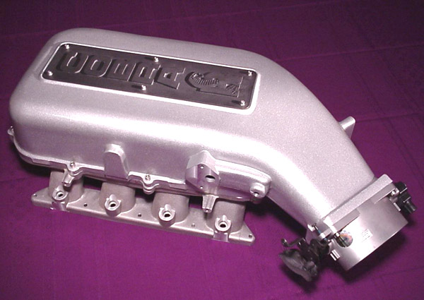
Don't know what you plan to use for air filter setup in your hotrod but you might be able to borrow a design feature from Subaru...
On my Outback (2.5L DOHC 16-valve) there is a pretty large central plenum feeding the 4 long legs of the "spider". Since this is a car meant to be driven easily by soccer moms they needed it to be smooth at throttle tip-in, so they put a big air tank/resonance chamber (not for power tuning but for acoustics) immediately at the other side of the throttle body with the idea being that there is a large volume of atmospheric pressure air right there at the TB input for when the TB changes position, rather than waiting for "extra air" to have to rush in all the way from the air filter.
Don't know quite how well it helps but the car is certainly very smooth to drive, and they used this concept in one form or another for the next 18 years after my car was made.
04-09-2017, 10:00 AM
#55
Rennlist Member
Thread Starter
Thanks, Greg.
Most of it stems from an early realization that if you need or want something, you might be able to just make it for yourself rather than having to look for and buy it. The other part of it is the trick of having the tools and equipment, or ready access to them, to do any of the fabrication tasks needed. With all of that I have taught myself to work in several different mediums and with many kinds of materials. Beyond that the limit is only in my imagination. I have found that if I can conceive of something I can probably make it. The limitation is in my ability to conceive of something; and that relates to some areas, particularly in the field of electricity or electronics.
Most of it stems from an early realization that if you need or want something, you might be able to just make it for yourself rather than having to look for and buy it. The other part of it is the trick of having the tools and equipment, or ready access to them, to do any of the fabrication tasks needed. With all of that I have taught myself to work in several different mediums and with many kinds of materials. Beyond that the limit is only in my imagination. I have found that if I can conceive of something I can probably make it. The limitation is in my ability to conceive of something; and that relates to some areas, particularly in the field of electricity or electronics.
Last edited by Jerry Feather; 04-09-2017 at 10:26 AM.
04-09-2017, 11:09 PM
#56
Rennlist Member
Thread Starter
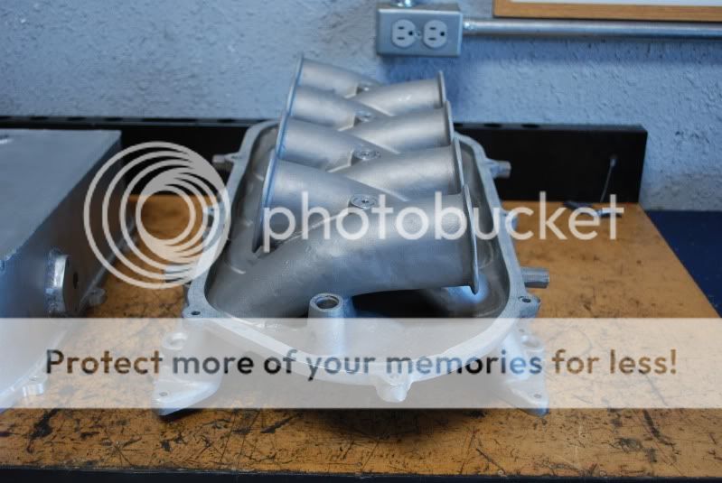
I did some machine work on the top plate including truing up the edges then rounding them at a 3/8 inch radius with a corner rounding mill bit. The rounding I think softens the otherwise kind of "heavy plate" look it has with square edges. Then I drilled and recessed all of the screw holes.
I have ordered some socket head screws and some nut plates to mount the plate with. Now that I have the plate cut to size I can do the final fitting of all the pieces and then begin to weld or get it welded together.
I have also cut some sample grooves/fins in a piece of the plate scrap with a small taper mill bit just to see how wide they might want to be. At .400 in. spacing they come out so that the top of the groove is about .290 and the top of the fin is .110. That's pretty close to what I want, but now I have to see if I can get them spaced correctly in the top plate. I don't want the fins to be much or any narrower, but I might go to a slightly small taper bit for the grooves.
The three holes in the middle of the top plate are for three posts that will connect the top plate to the bottom of the plenum.
04-09-2017, 11:16 PM
#57
Nordschleife Master
Fantastic fabrication work! By the way, I didn't want to pollute your thread with plenum size arguments. Sorry about that. On the plenum construction, Todd Tremel I think has some experience in not only making an intake for 928 but also constructing real pressure vessels. You could ask him for informed opinions on the plenum construction.
04-10-2017, 10:57 AM
#58
Rennlist Member
Thread Starter
Thanks P-2. If there were an argument about plenum volume, this might be the right place for it, except that I have pretty much locked myself into this size every early on with all the compromises I had to make in meeting my design goal - - lower profile. Is Todd Tremel on here? Likewise, though, I am pretty well stuck with what you see here. The only thing I might do different is anything, but only if this one doesn't work almost at all, and I don't see that happening.
For Carl's inquiry about the plenum volume, I forgot to deduct the volume of the MAF tunnel in the rear bottom, but I haven't calculated that yet. I think it might be only about 10 or 12 cubic inches. The same for the little one in front, but only about 3 or 4 cubic inches. Then, I found online something that suggests that the volume inside the tubes is also part of the plenum volume. There again, all of this is purely academic at this point.
For Carl's inquiry about the plenum volume, I forgot to deduct the volume of the MAF tunnel in the rear bottom, but I haven't calculated that yet. I think it might be only about 10 or 12 cubic inches. The same for the little one in front, but only about 3 or 4 cubic inches. Then, I found online something that suggests that the volume inside the tubes is also part of the plenum volume. There again, all of this is purely academic at this point.
04-10-2017, 06:26 PM
#60
Rennlist Member
Thread Starter
Interesting, Tom.
I couldn't wait any longer to try to cut the grooves/fins in the top plate, so I laid out the outlines to mill up to and set it up in the mill. I made real good progress until I got about halfway and had to move it on the mill table, but after I got it moved I didn't clamp it down well enough and had my clamps kind of off to one end leaving too much leverage for the mill bit to push it out of alignment.
Here are some pictures of my progress then of my failure. The only upside to this is that I still have some material to work with to start over, and I can take an opportunity to give any reconsideration to my design and maybe even the layout of the mounting screws, perhaps so that they come out more like they relate better to the grooves. That may be too hard to lay out for what little that might matter.
Aside from reconsidering my design I at least can simply duplicate what I have done to this point without going through all the planning and figuring that I did to get this far on the plate.