When you click on links to various merchants on this site and make a purchase, this can result in this site earning a commission. Affiliate programs and affiliations include, but are not limited to, the eBay Partner Network.
Wiring diagrams to the rescue! If you have a copy of the 1980 wiring diagrams in your Workshop Manual, follow along on that. If not. look at the section I patched in below. The switch contacts in the diagram are shown in their relaxed position, with no pressure applied.
The two switches are SPDT (single-pole, double-throw, or form-C) wired in parallel.
-- Ignition-on (circuit 15) power from fuse 10 enters both switches at the 82a contact (form-C, the "A" contact) via a black wire. In the relaxed position with no brake system pressure applied, the 82a contacts are not connected to anything internally at either switch.
-- When pressure is applied to both switches at the same time, typical to brake application with both systems holding pressure, each 82a pin is connected with its respective 81 pin. The brake light bulbs connect to both of the 81 pins with black-with-red-tracer wires, via the "lamp control unit". No power is passed though either switch 81a contact to the warning system.
-- When pressure is applied to one switch only, that switch connects its 82a and 81 pins, so the brake light bulbs still light up. The switch that has no pressure still has 81a and 81 connected. Power to the warning system is then passed through the first switch 82a to 81, then in the second switch power passes from its 81 pin to 81a to the warning system using blue-with-brown tracer wire.
That sort of solves the brakelight concern, but... The early cars have diagonal-split braking that can fail on one side and seem to provide OK braking. The original switches work very well. Just replace them in matched pairs with good pieces.
I believe the choice to use a separate switch is primarily so there is no need to splice into the factory harness (for the Infinitybox electrical system and the brake input), as there seems to be no easy place to do that. The pressure switches look brand new and I believe are working perfectly. The external brake pedal switch will avoid "butchering" that important part of the wiring harness. There are already enough "creative" and undocumented incisions made by a previous individual...
Dr. Bob, thank you for posting that helpful bit of information. We would still have been searching for it if you hadn't chimed in.
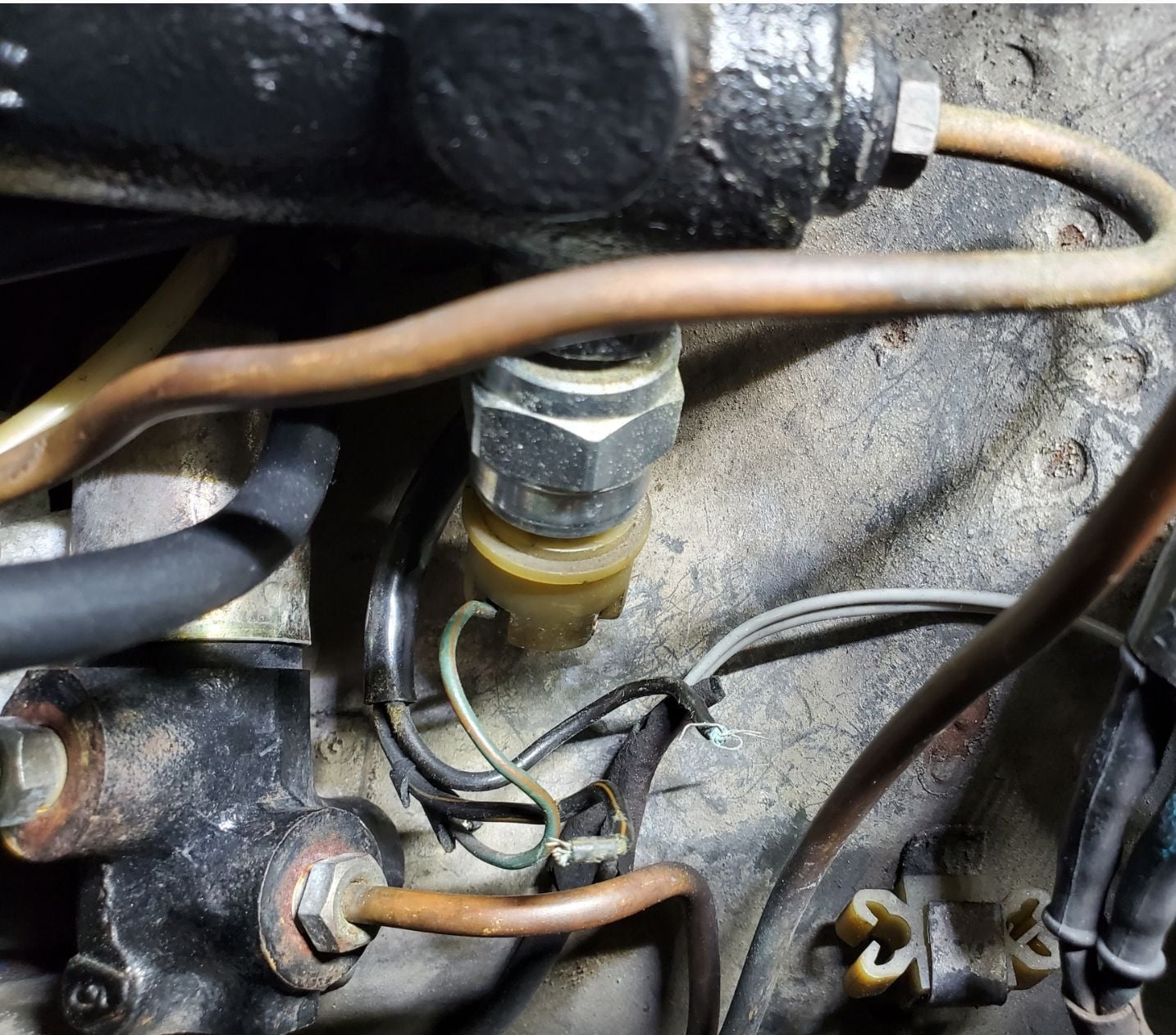
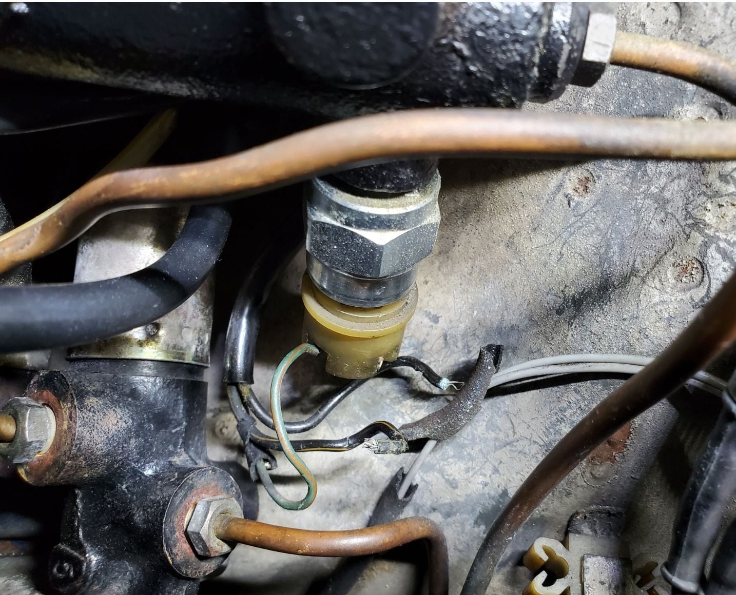
The wires at one of my master cylinder pressure switch connectors broke away. Master cylinder and switches are new. Other connector is intact and plugged into the one pressure switch.
Broken pressure switch wires
Another view
I put new wires onto the broken ends and tried to keep the color scheme going.
Original black wire is very dark brown
Green wire with red stripe is now green
Black wire with yellow stripe is yellow
When I had them connected this way, I was getting a brake pressure warning. I tried a different wire combination and still had the pressure warning, but this time the lights were on all the time when the key was on.
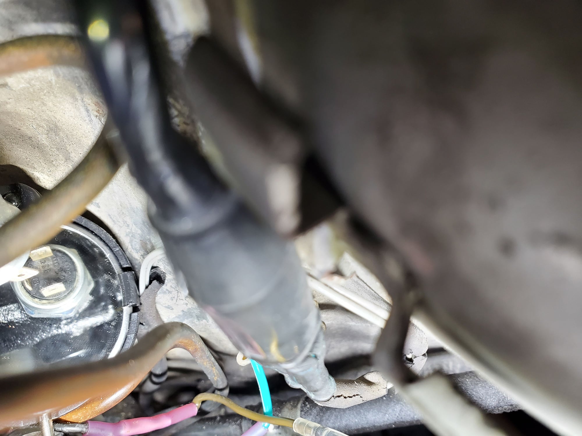
I then found this thread and took a mirror to get s picture of the terminal numbers on the pins...
Mirror view of pressure switch
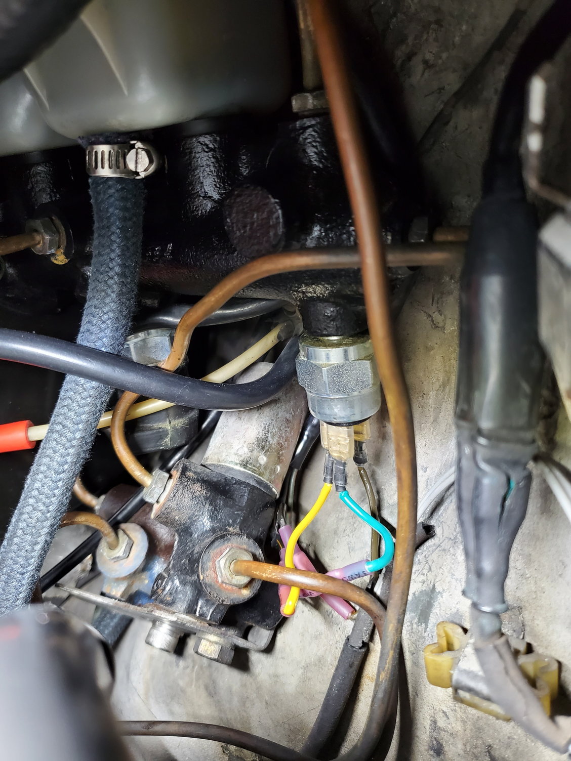
Wires connected
So, I now understand that pin 82a should get the black (now brown) wire. I also took my meter and tested this wire. It's the only one that gets 12v when the key is on, so that wire is on pin 82a which is the closest pin to the fender wall. Now the brake lights aren't on anymore, but...
Now they don't come on at all unless the car actually has to be running for them to work and not just in the full accessory position?
I've tried the other 2 wires on the other terminals in both combinations and no brake lights. Does it matter which wire goes to which terminal?

 09-20-2016, 12:15 PM


 T
T