When you click on links to various merchants on this site and make a purchase, this can result in this site earning a commission. Affiliate programs and affiliations include, but are not limited to, the eBay Partner Network.
Oh, I will be at SITM this year come hell or high water!
I made a mistake last year and was not able to attend.
I will be there this year with the Explorer full of tools, materials, and parts. A support vehicle if you will.
Last week, I tackled the headlight issue, and fixed it! And in the process, learned that I had wasted a bunch of effort. More on that later.
Back in post #63, I disassembled and cleaned the headlight relay. So, I was relatively sure it wasn't that. I focused on the headlight motor.
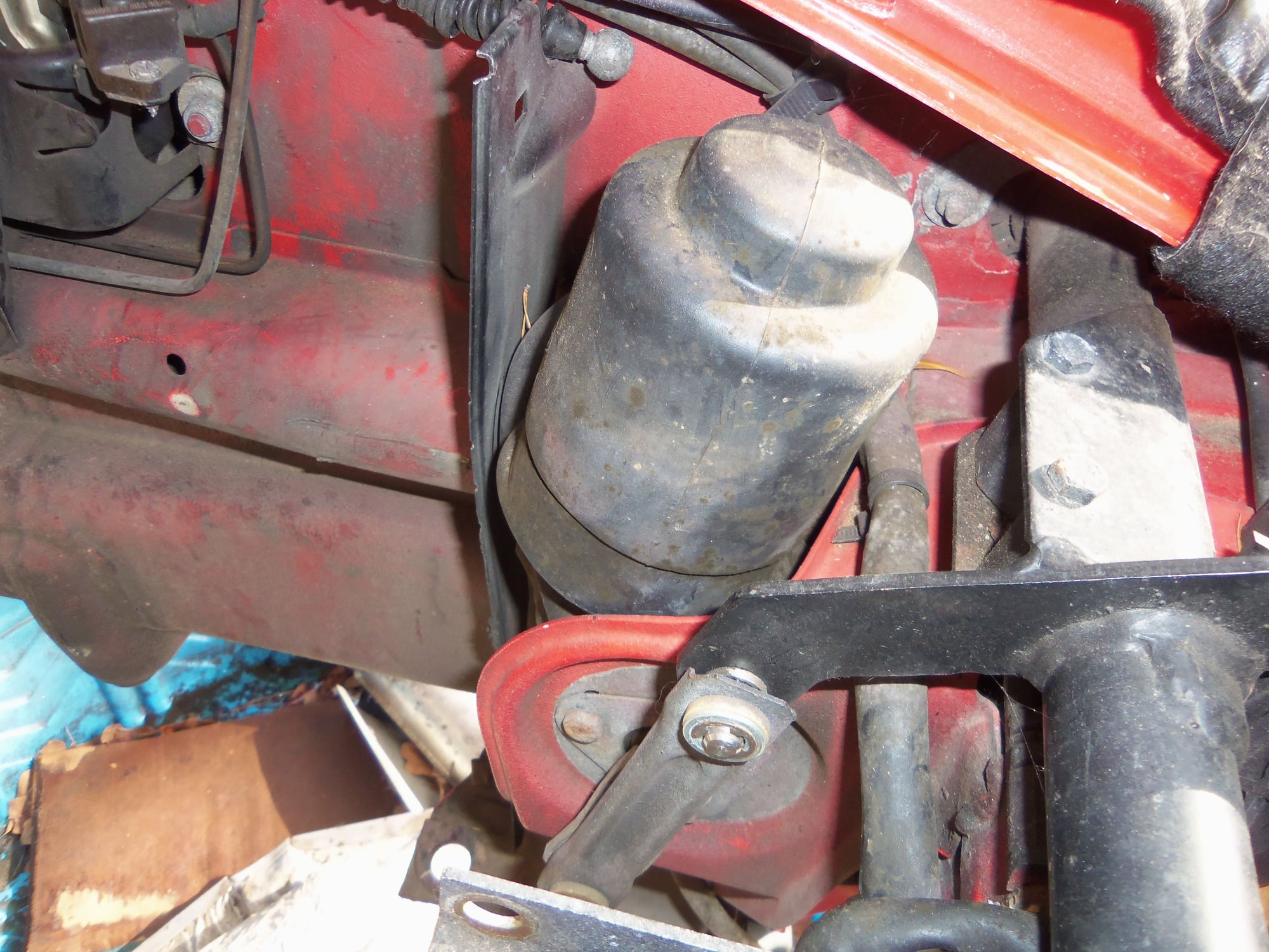
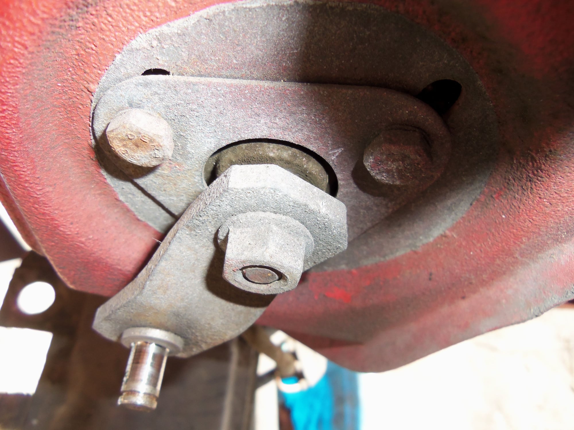
Removal wasn't terrible. I removed the linkage rod, then used a puller to remove the crank arm from the motor spindle shaft. Prior to that, I made match marks on the crank arm and the motor retaining plate. I wanted to be able to reposition the motor for proper alignment of the linkage rod.
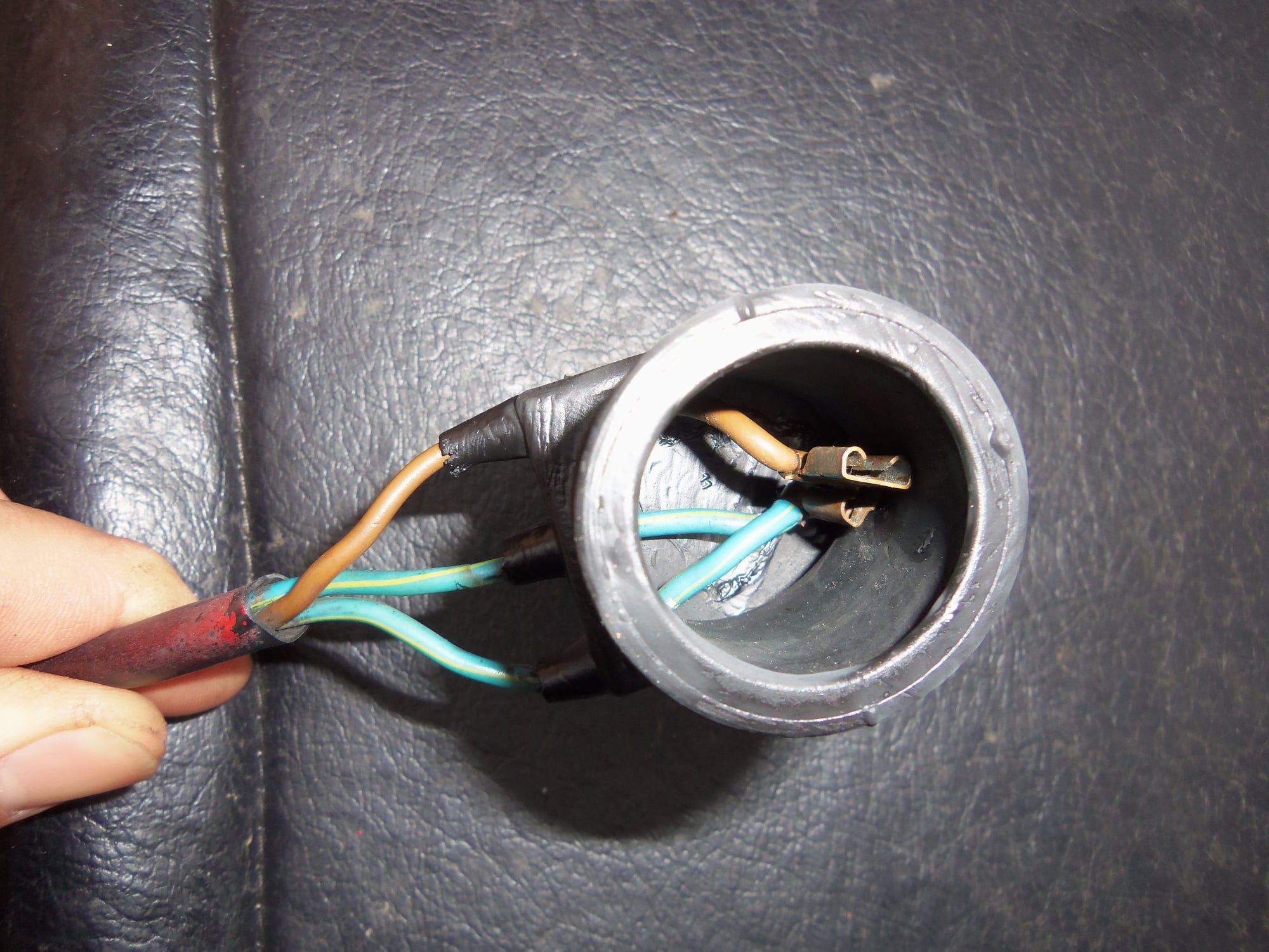
The motor was a little fiddly to wiggle out of its hole, but it came. Removing the four wires was another story.
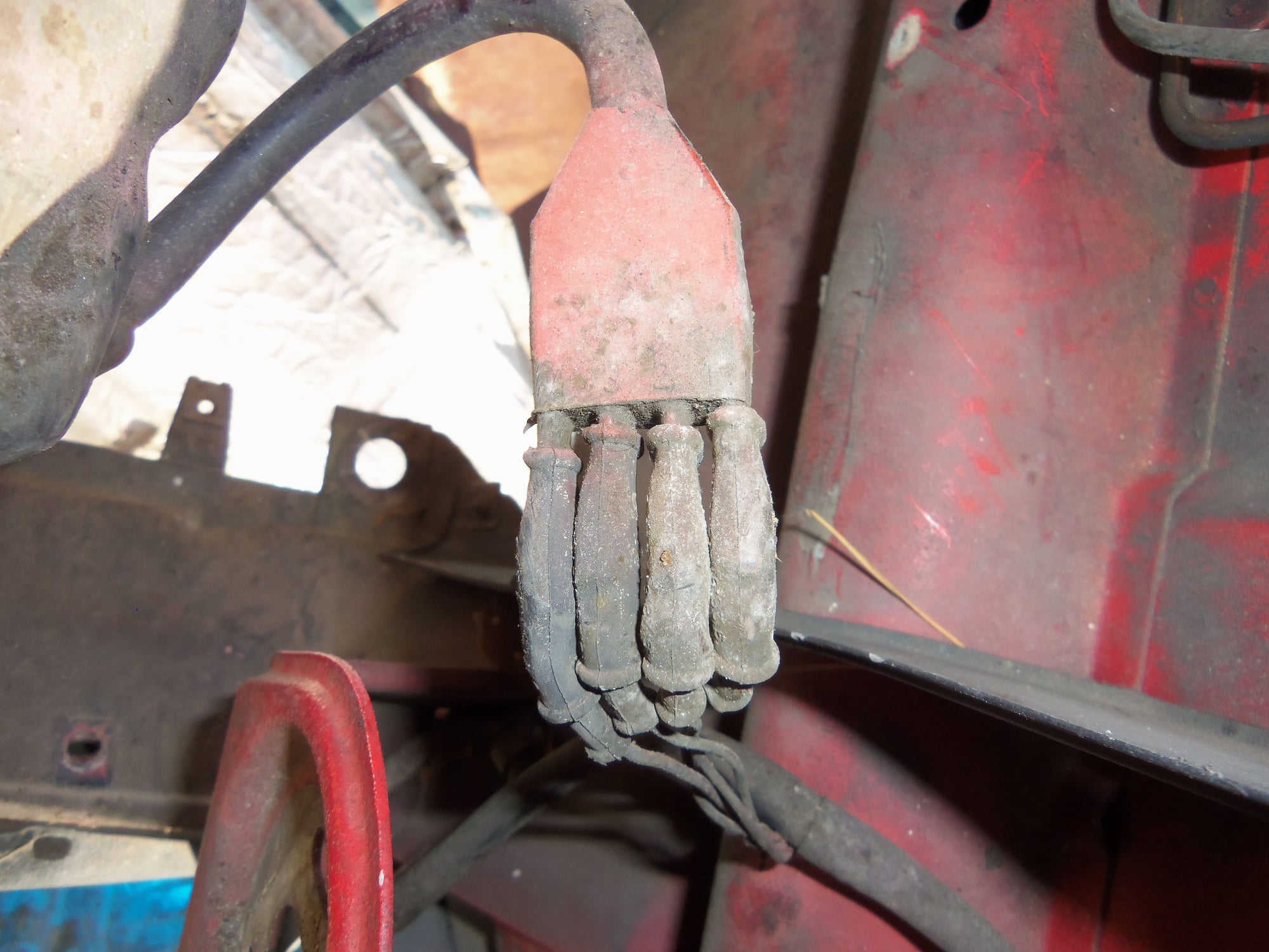
The four female spade connectors would not release for love nor money. Eventually I figured out that each female had a tiny locking tab that engaged with the male terminal. After I damaged two of them. I made careful notes of which wire went where for the connector. A Rennlister had issues with the wiring diagram for his not having terminal numbers. I checked the 1986 US lamps diagram, it has numbers and wire colors. Good to go.
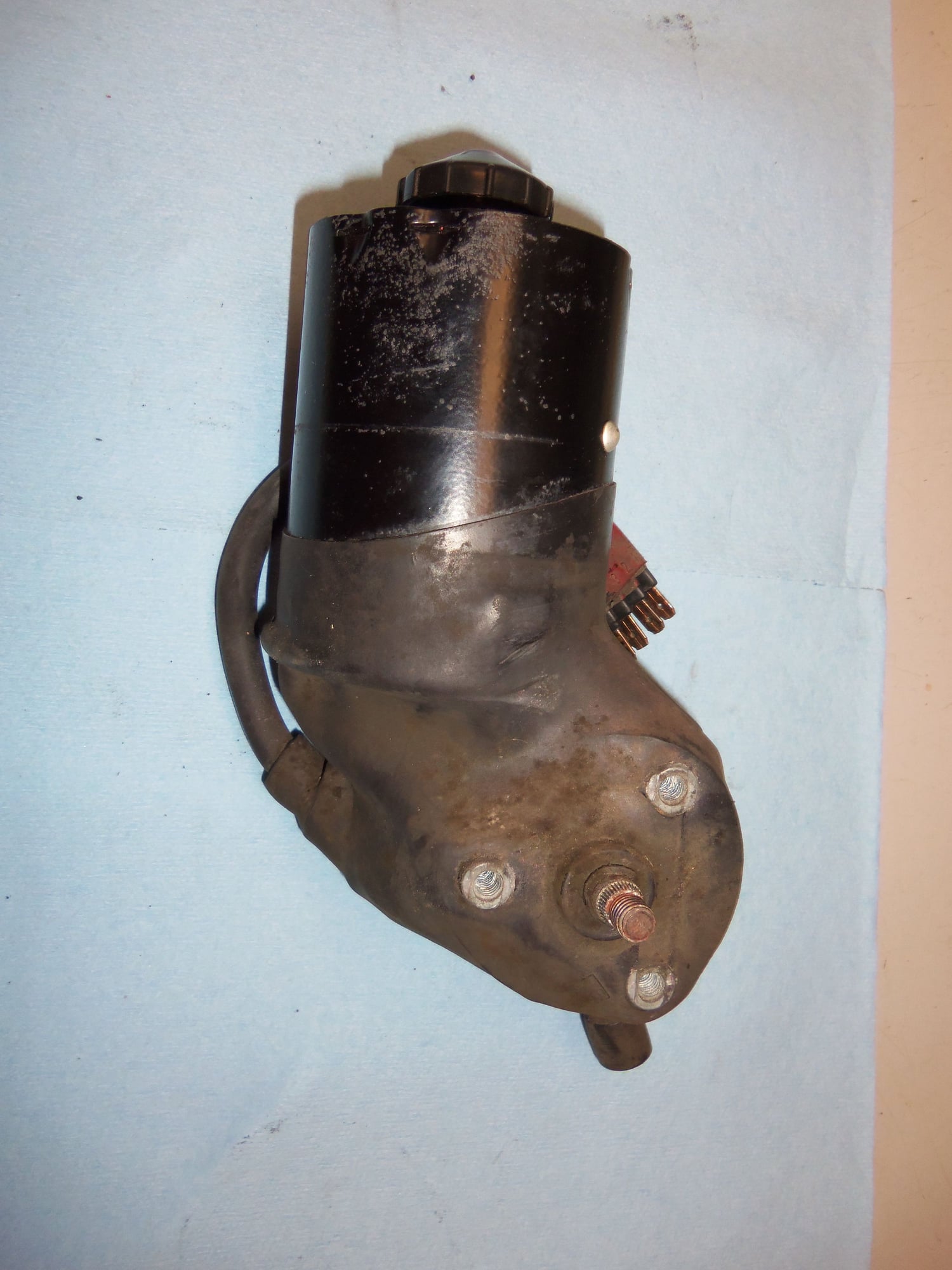
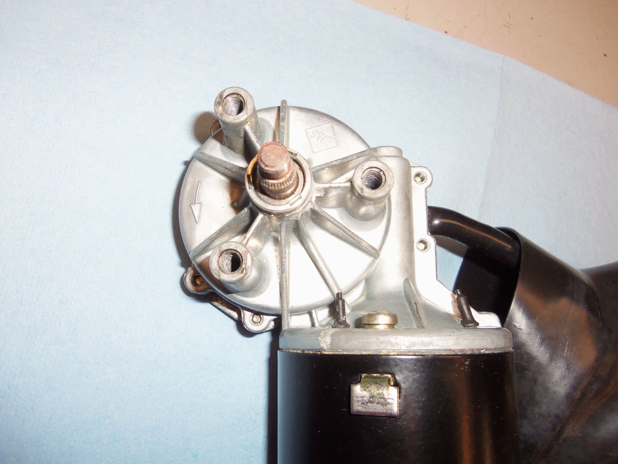
Headlight motor and linkage.
Showing how the linkage rod overlaps the crank arm.
Linkage rod and oh-so-important E-clips.
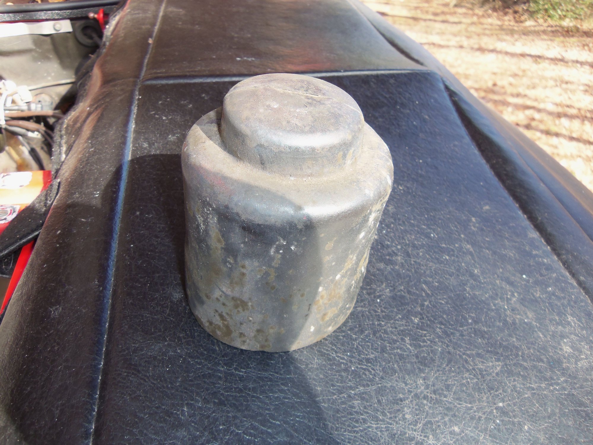
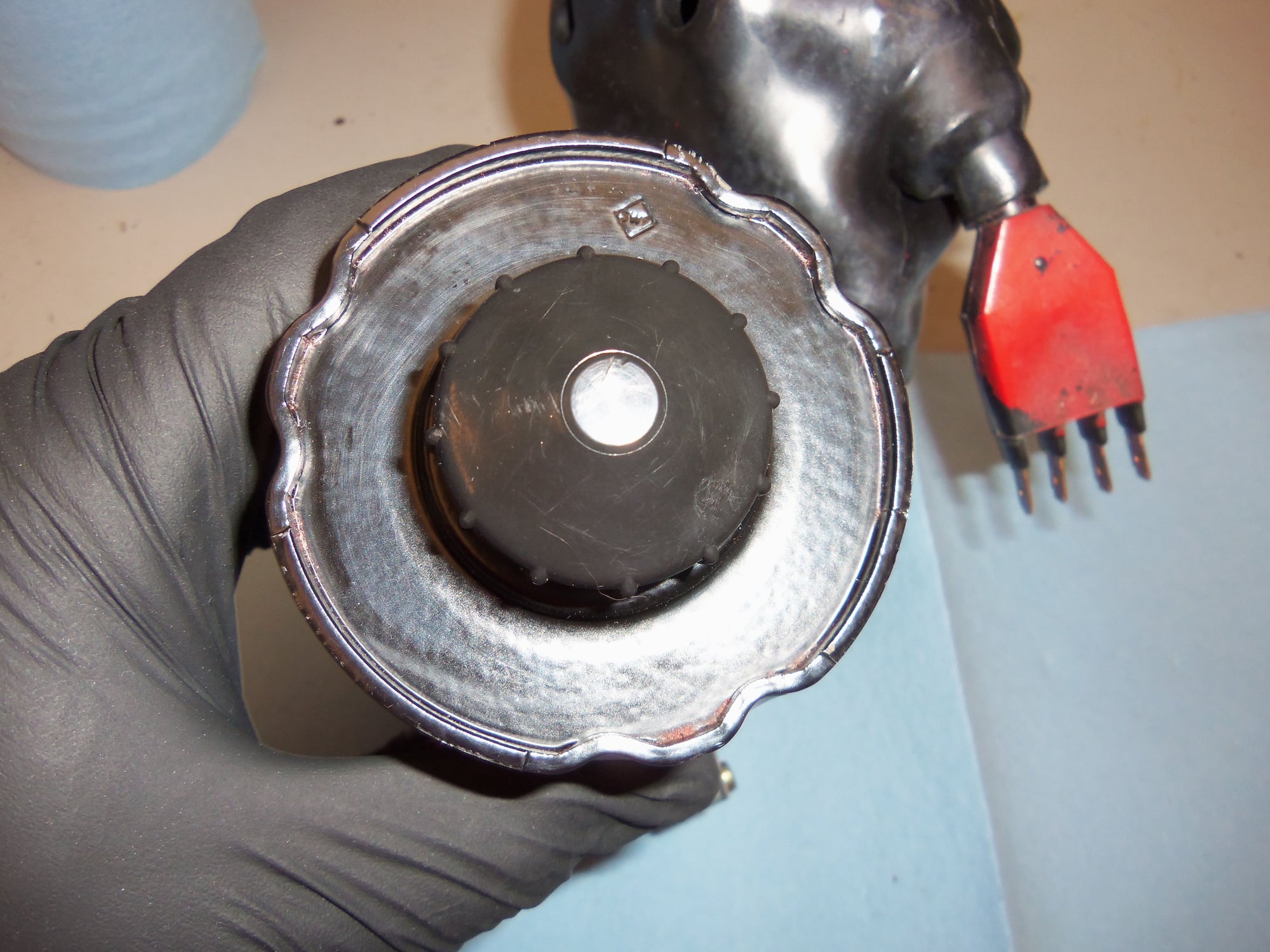
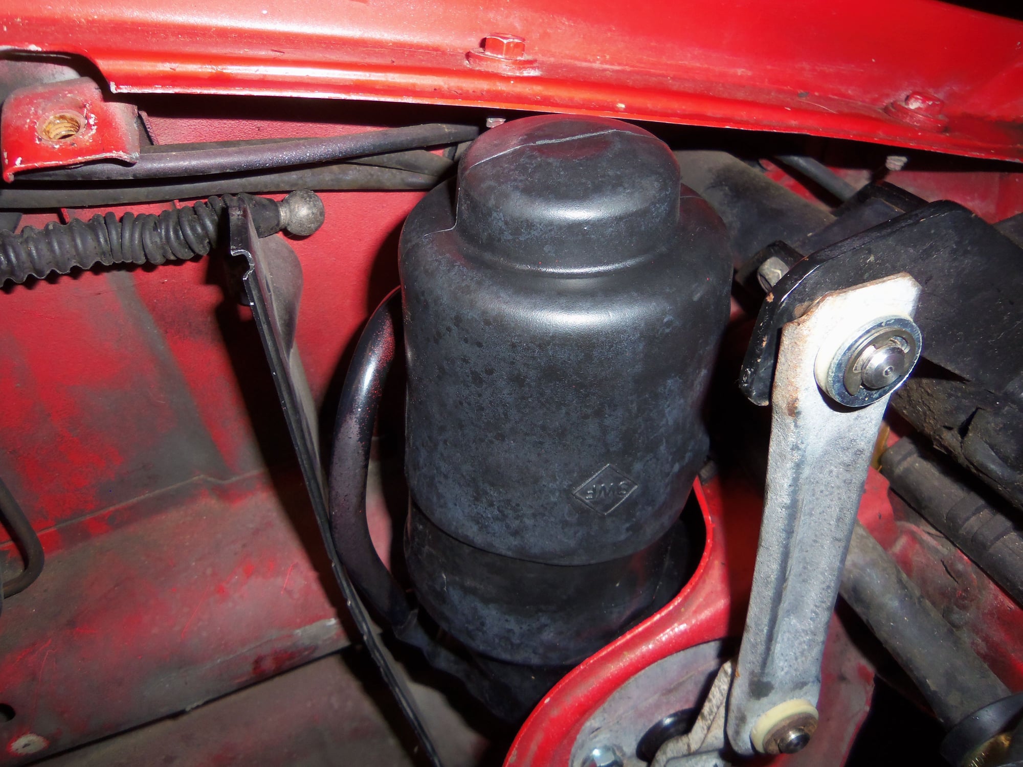
Rubber cover for the end of the motor.
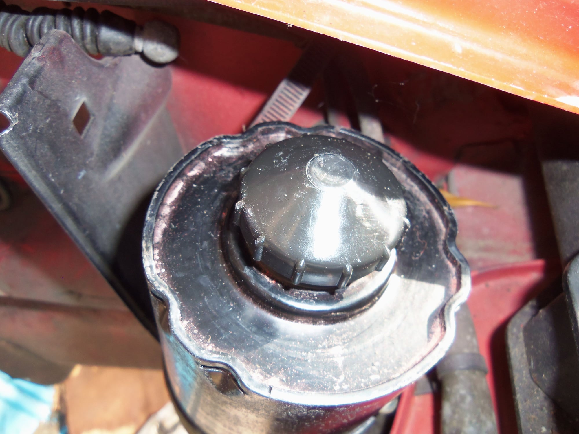
Manual actuation ****, that hides under the rubber cover.
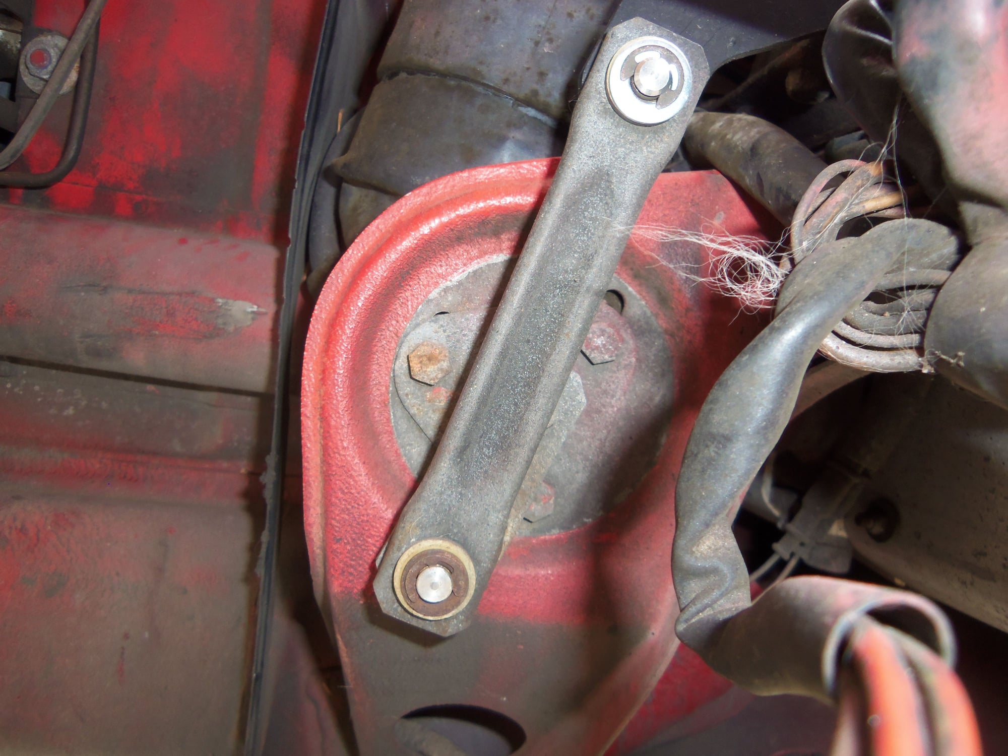
Crank arm with the linkage rod removed.
Crank arm.
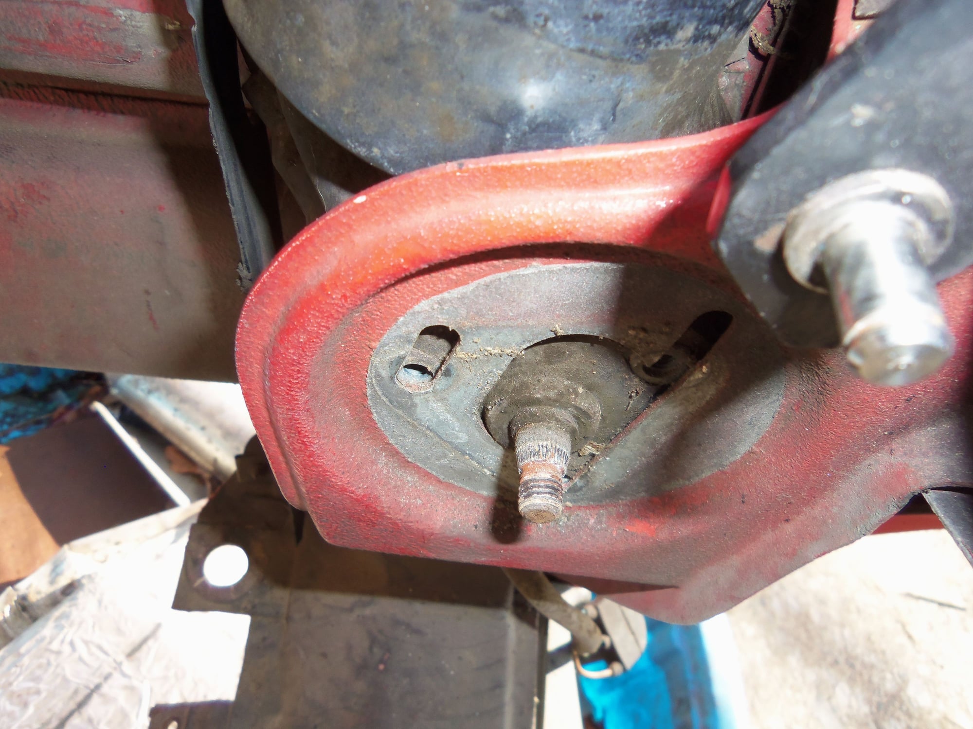
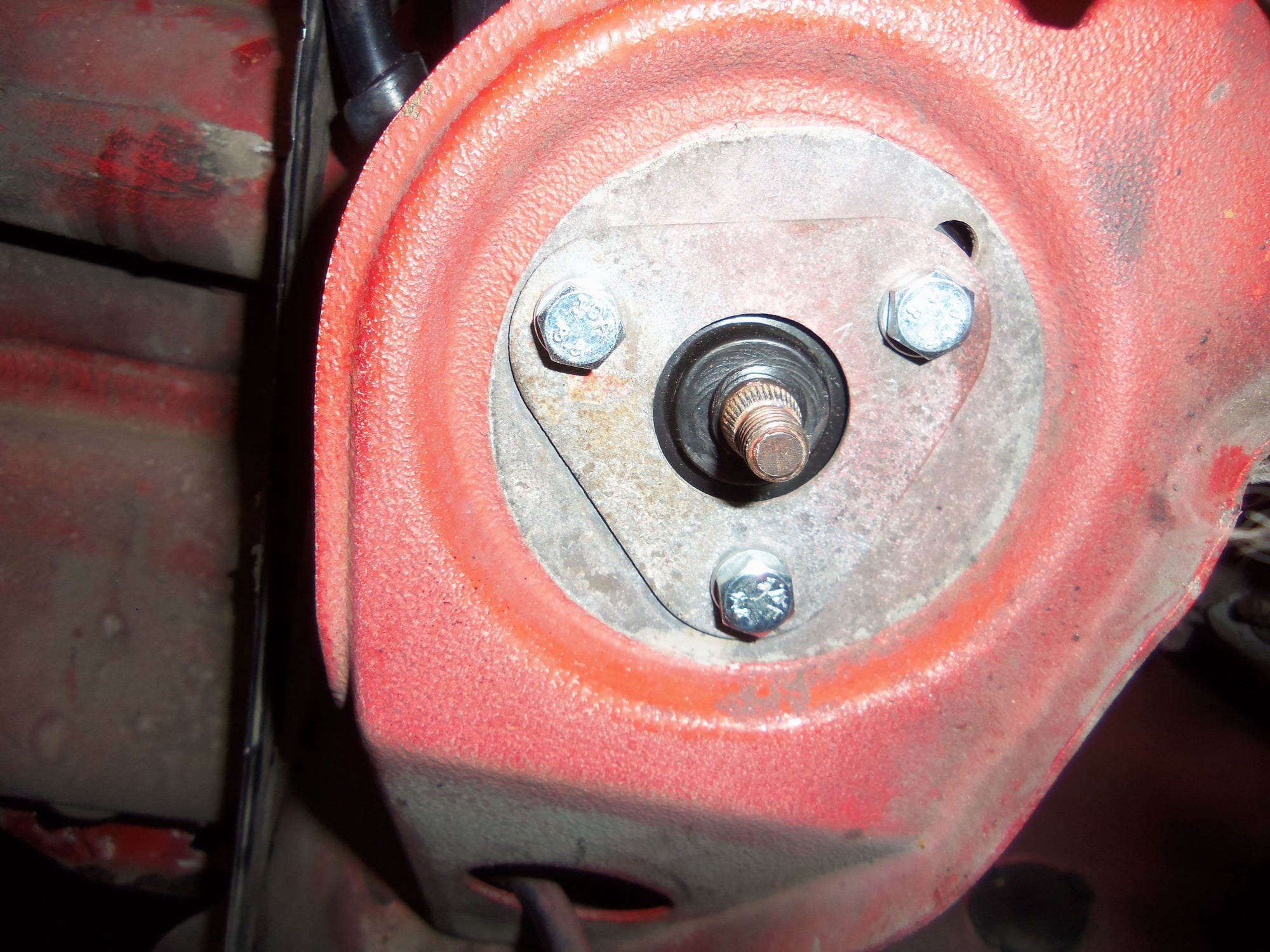
Crank arm removed, female splines in the hole.
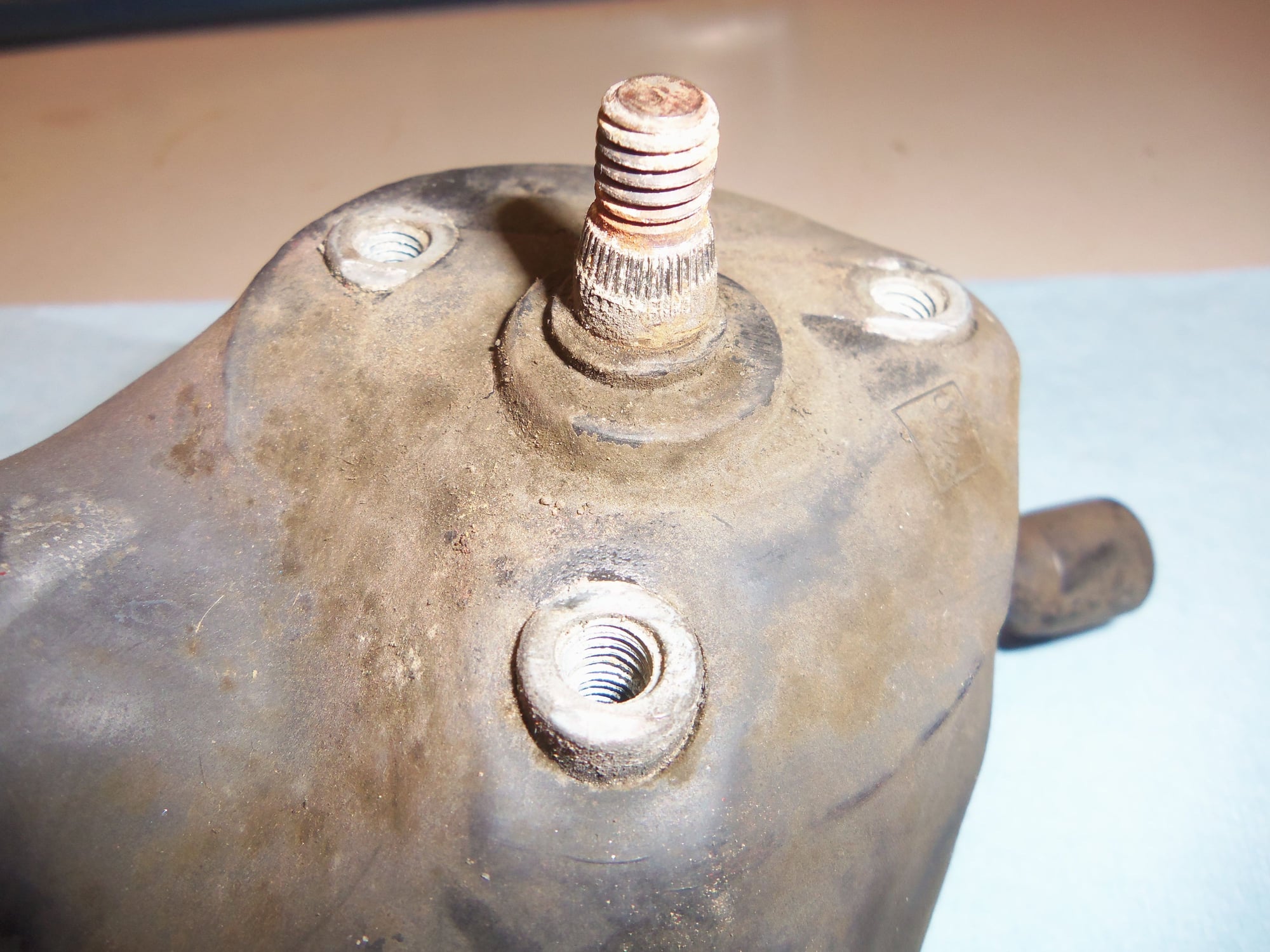
Crank arm and motor retaining plate removed. Male splines on the motor spindle shaft.
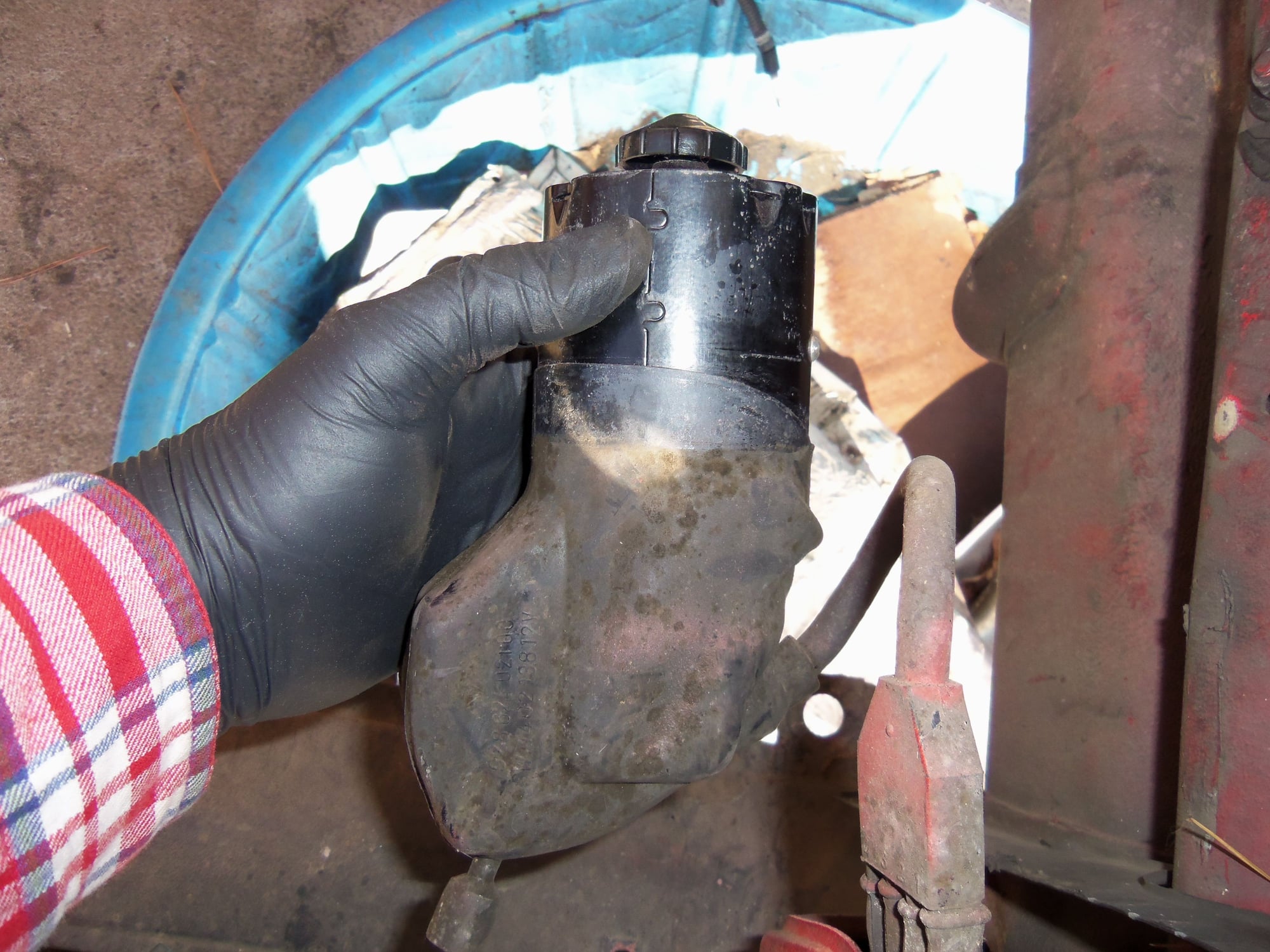
Motor free of its home.
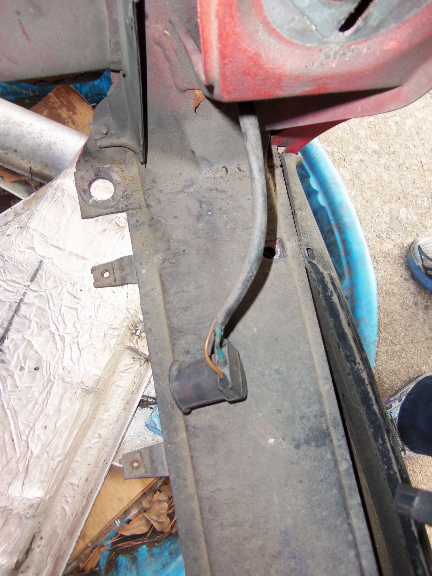
The wiring harness for the motor did not have much slack. I found that part of the harness continued down through the front body structure. I found a white(used to be white) harness clip, and then the wiring to the radiator temperature switch. I was able to release the harness clip and pull the radiator wiring up. This gave me slack to work with the headlight motor wiring.
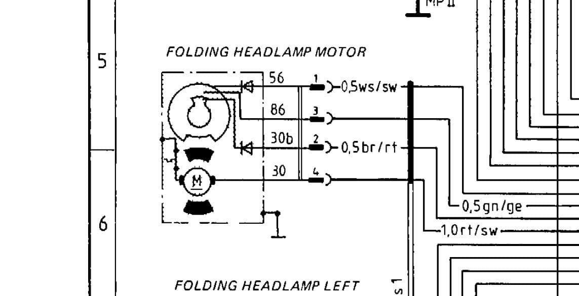
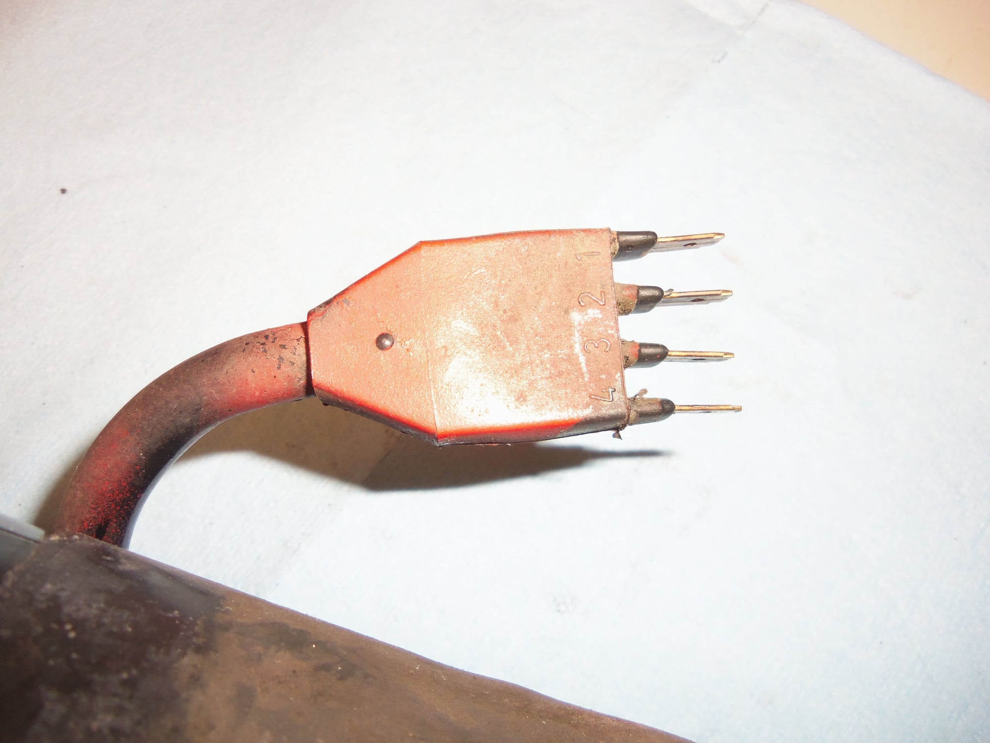
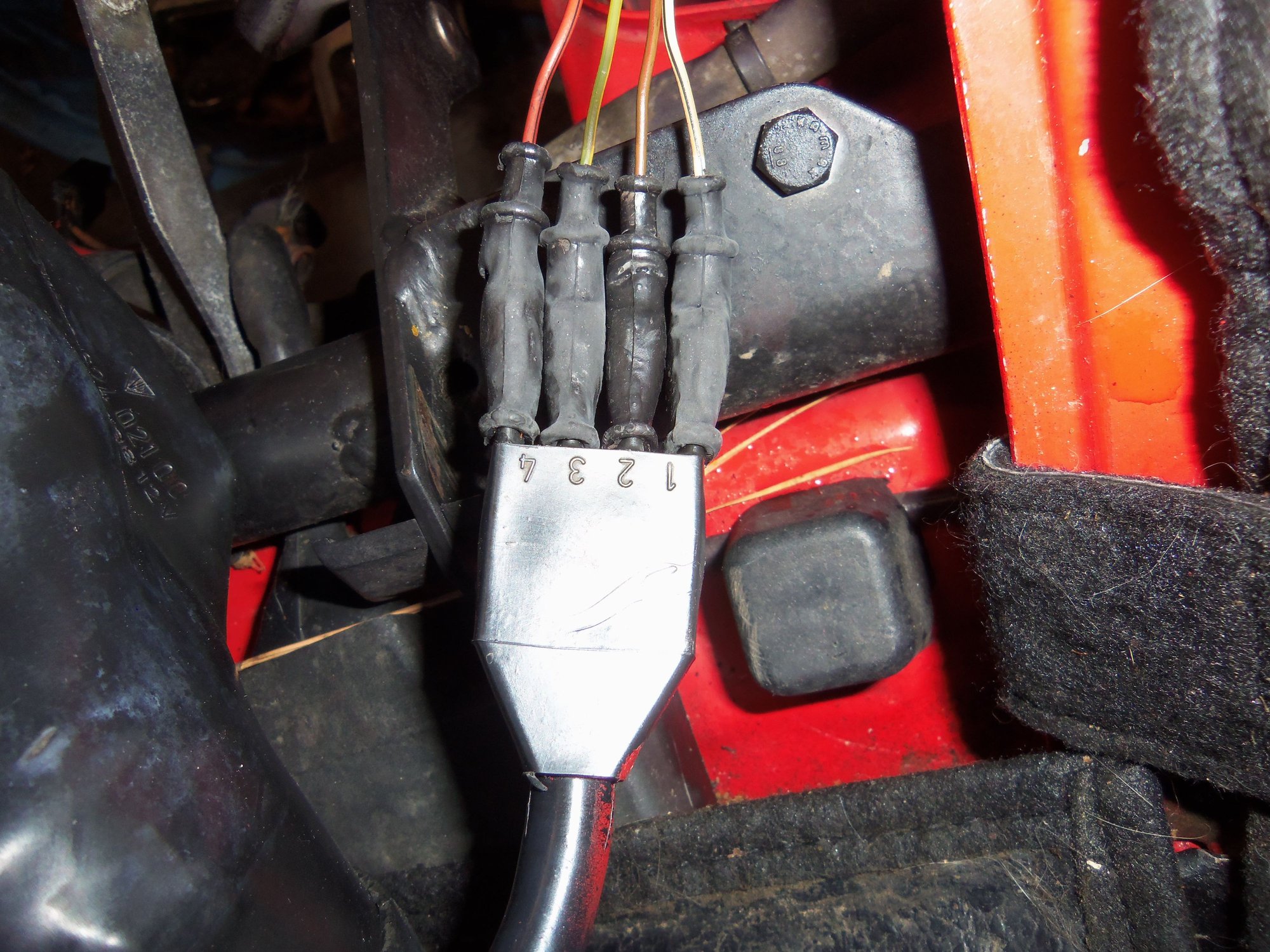
The headlight motor wiring and terminals were as such:
This corresponds to the wiring diagram for 86 US Lamps.
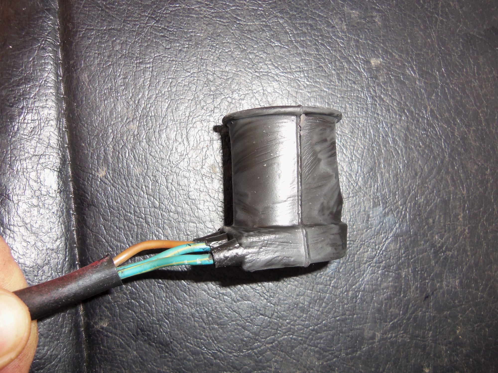
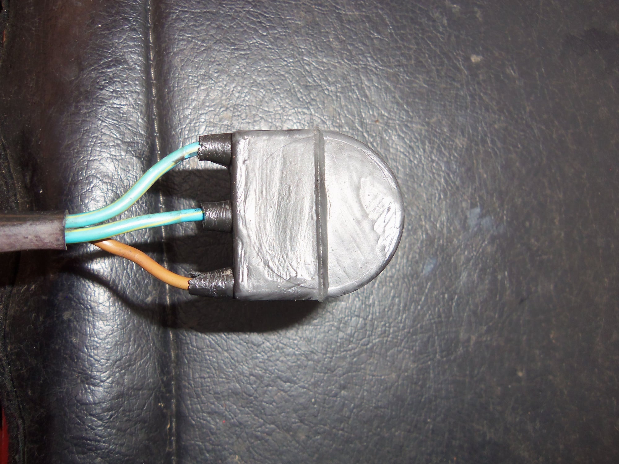
Mmm...cruddy.
Not as cruddy after wiping off with a mineral spirits wetted rag. Now able to see the wire colors.
Slack in motor wiring harness prevented by the rest of the wiring and this harness clip.
The rest of the harness led to the temperature switch connectors for the radiator.
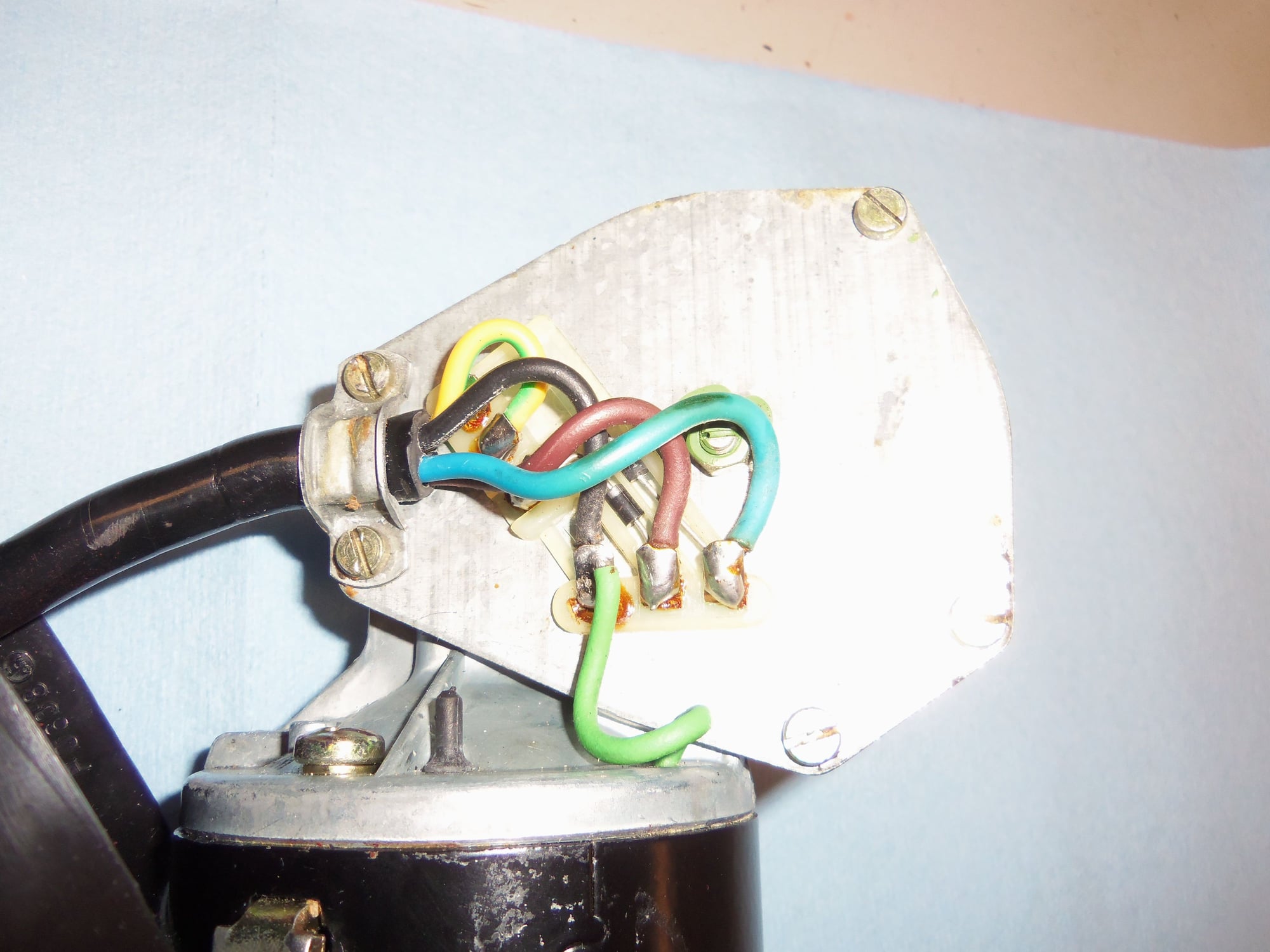
Headlight motor wiring.
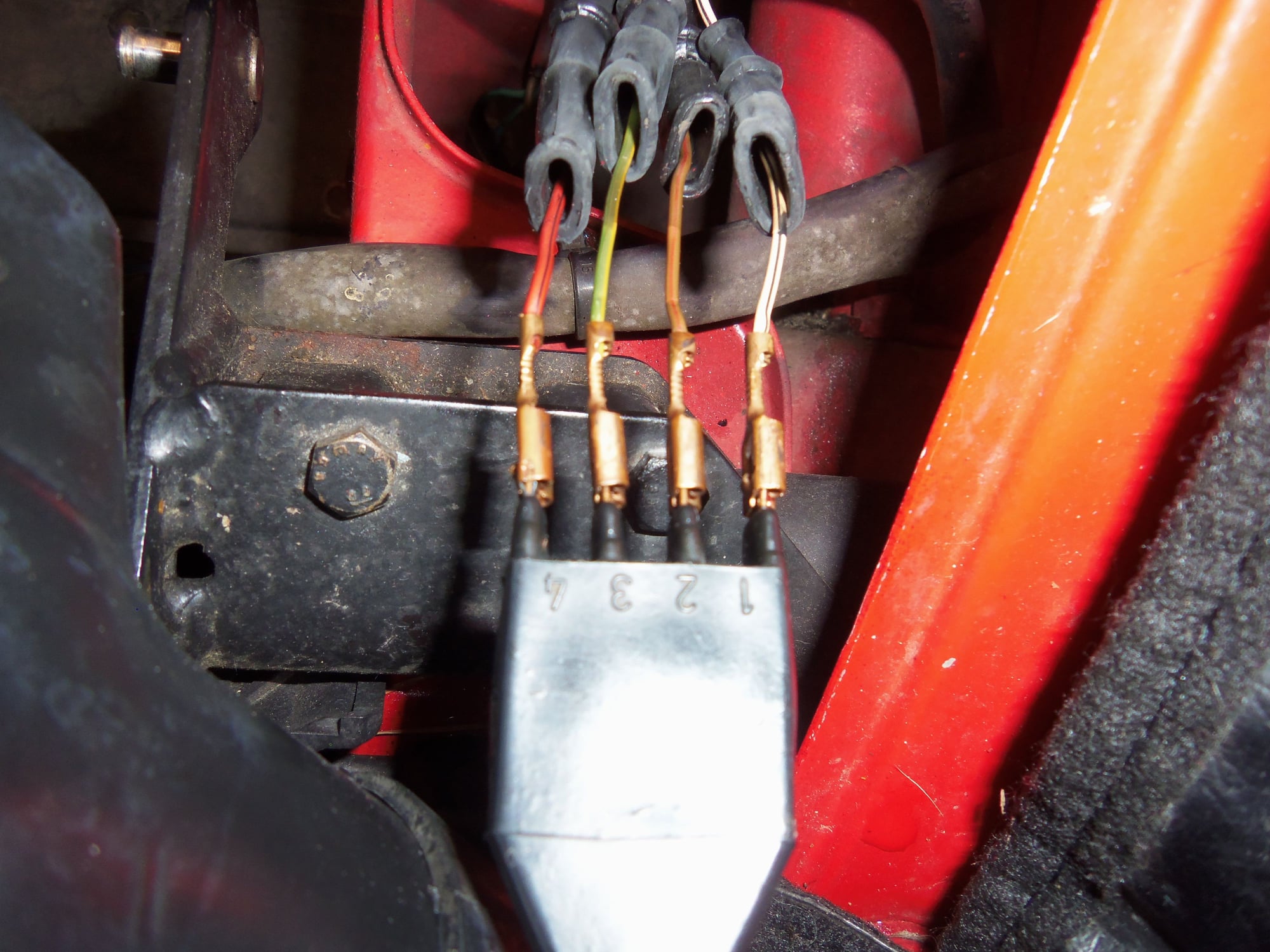
1 = ws/sw (ws is white, sw is black, so white wire with black tracer)
2 = br/rt (br is brown, rt is red, so brown wire with red tracer)
3 = gn/ge (gn is green, ge is yellow, so green wire with yellow tracer)
4 = rt/sw (rt is red, sw is black, so red wire with black tracer)
Also worth noting, wire 4 is the power wire to the motor. The motor grounds out through the casing. Wires 1, 2, and 3 are used for the relays to start/stop the motor, and turn on the lights.
With the motor out and on the work bench, I moved onto disassembly and cleaning.
All of the small pieces were scrubbed with mineral spirits and a tooth brush. The rubber cover for the top of the motor was cleaned inside and out with a mineral spirit soaked rag.
The rubber casing that covered the lower part of the motor and all of the gearbox was a b*tch in high heels to get off. It took much pulling, prying, and a few curse words to get off off without tearing. I did not pull it completely off as it would not clear the plug. I cleaned the casing in place with a mineral spirit soaked rag. I turned the casing inside out for the same kind of cleaning.
I wiped off the motor housing and the gearbox housing with yet another mineral spirit soaked rag. Both looked quite good. The rubber casing had done its job.
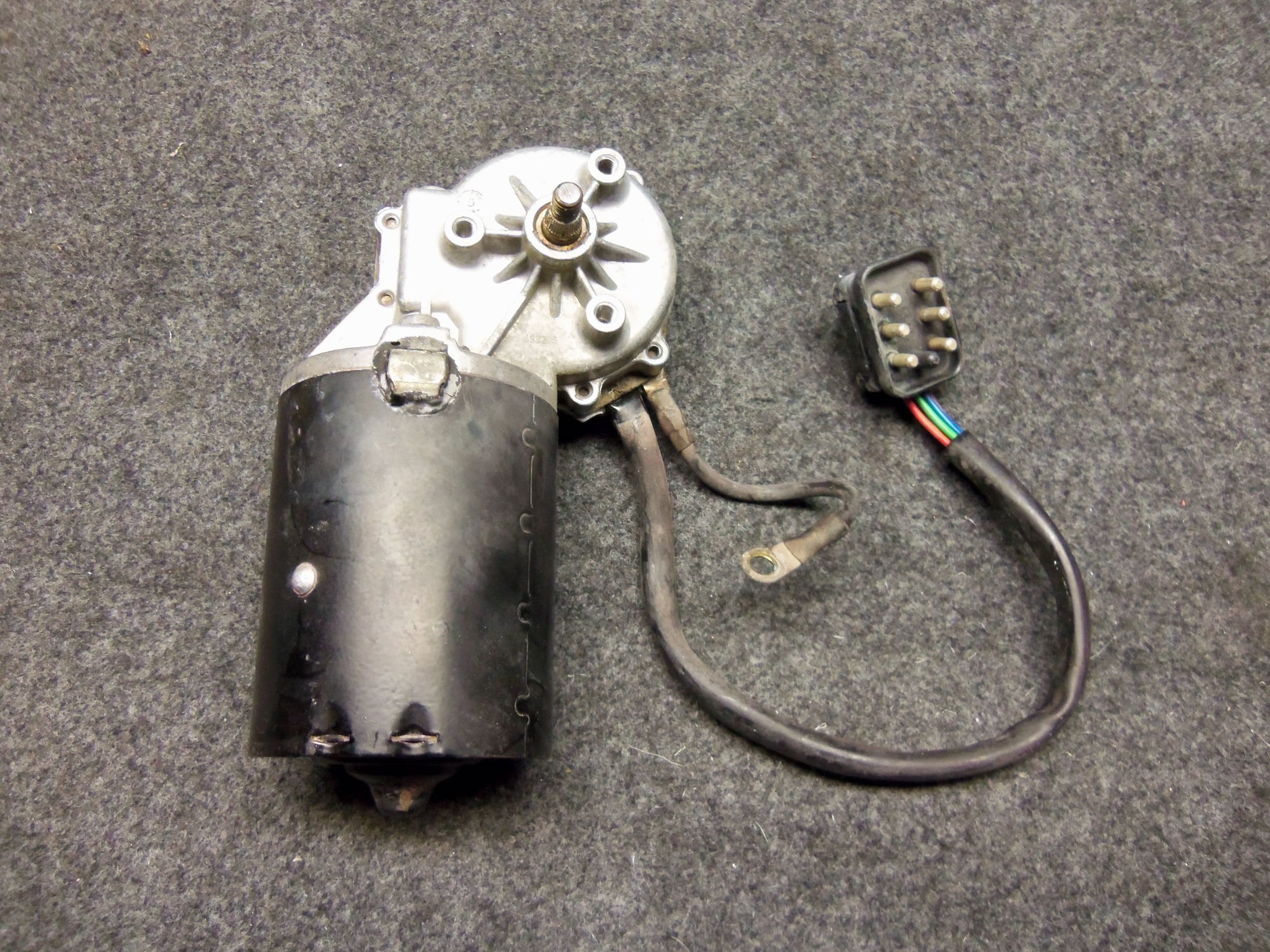
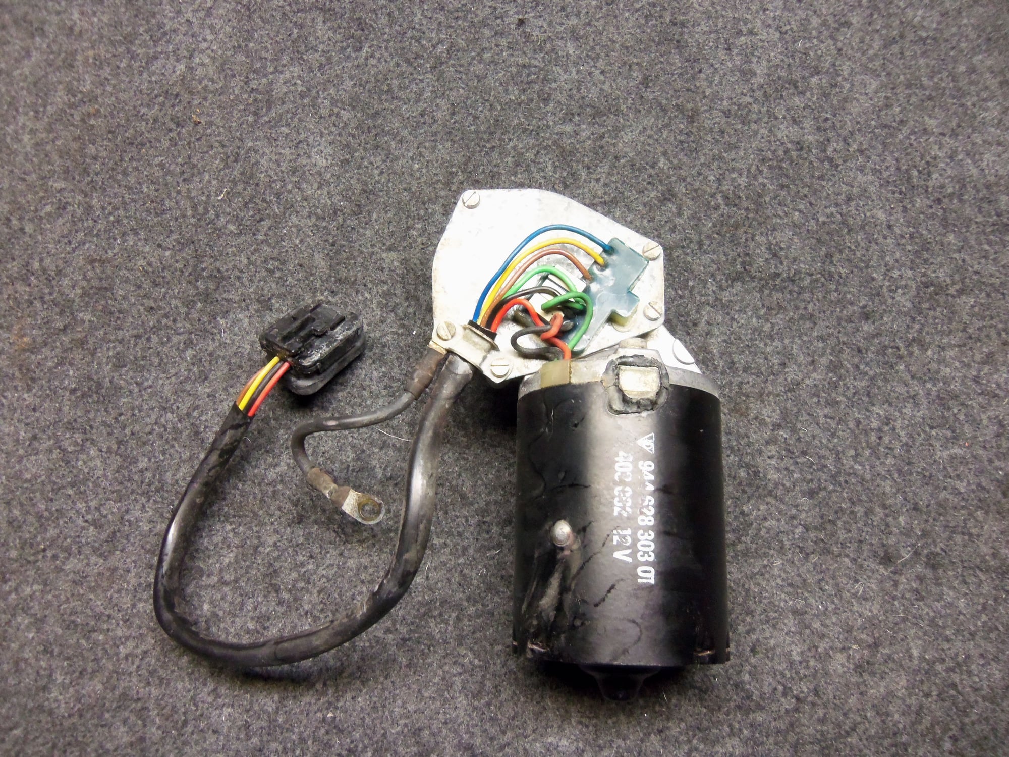
I did notice the motor looked suspiciously like the wiper motor. However, comparing photos of them, it is obvious the motors are not the same. They are made by the same company, though.
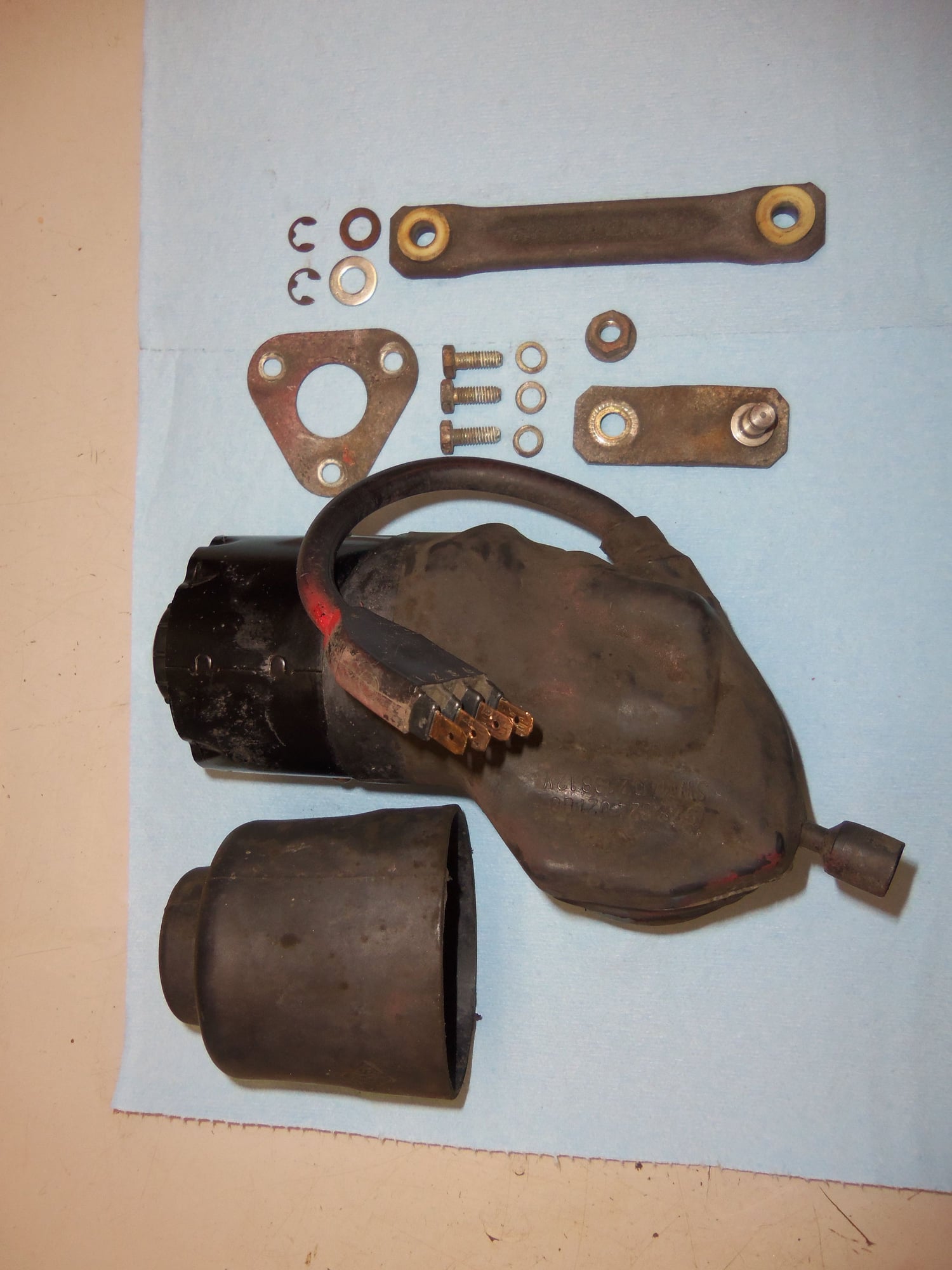
Parts and pieces.
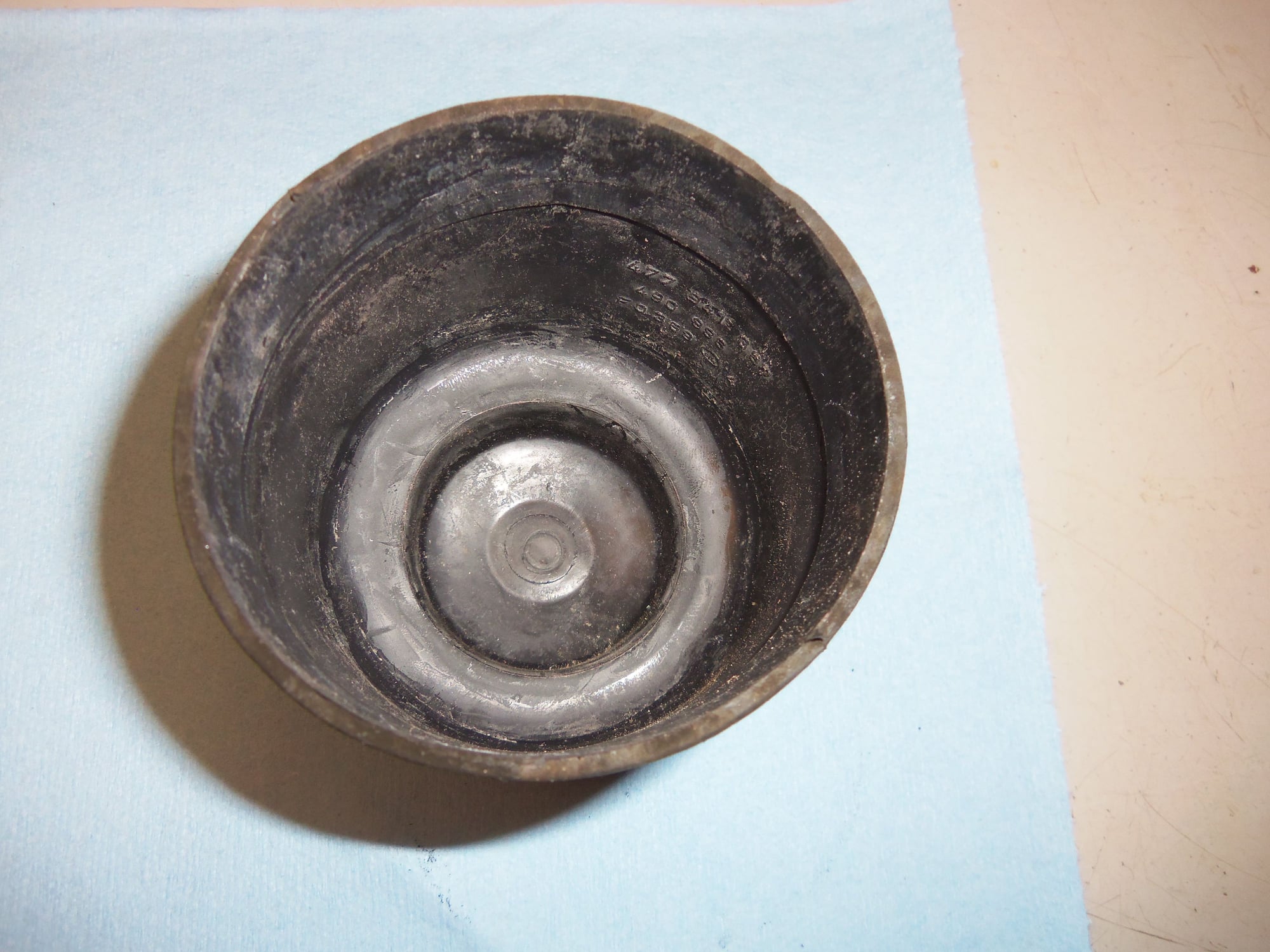
Inside of rubber cover for the top of the motor and manual ****.
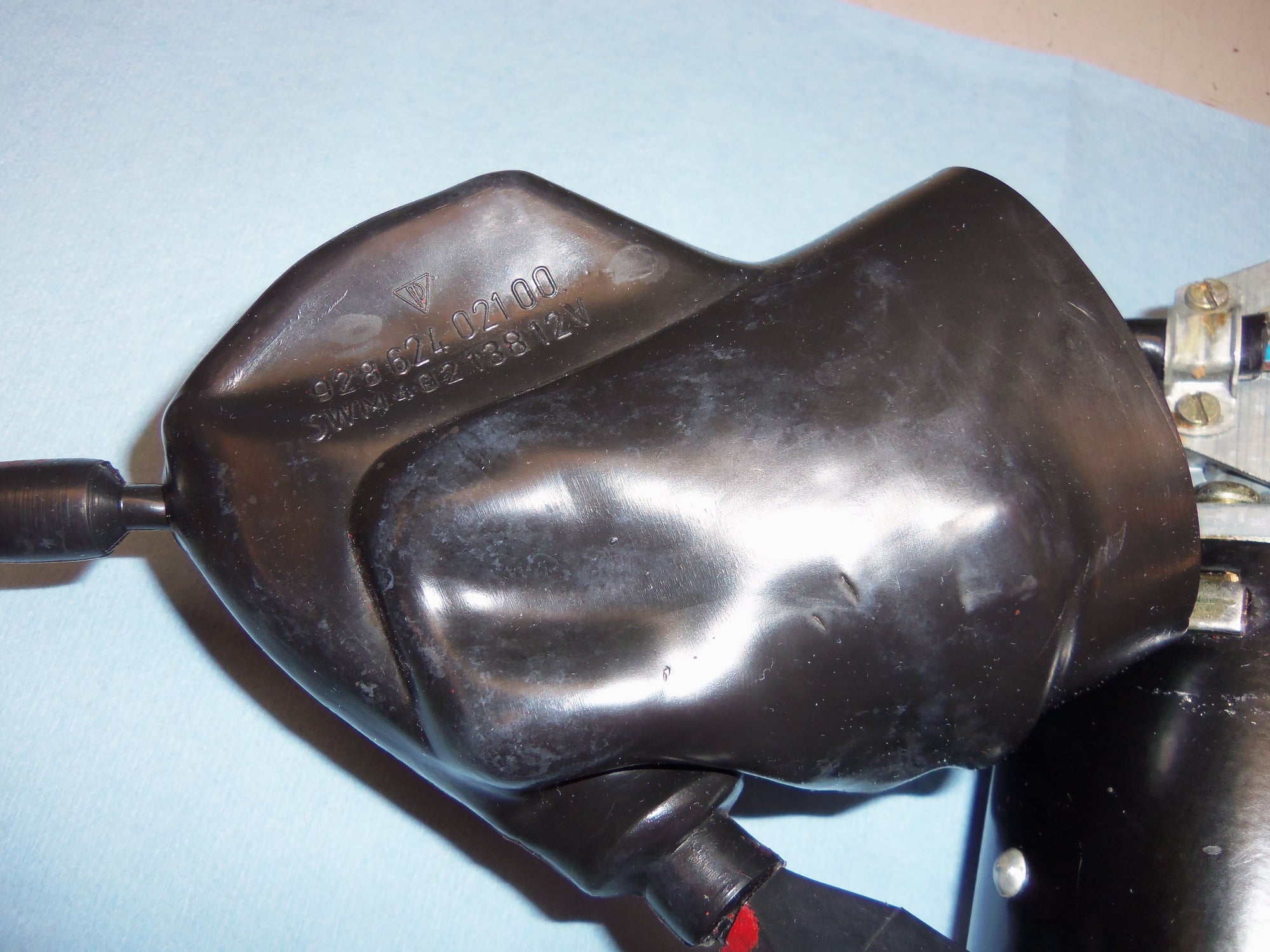
Rubber casing that covers the lower part of the motor and all of the gear box.
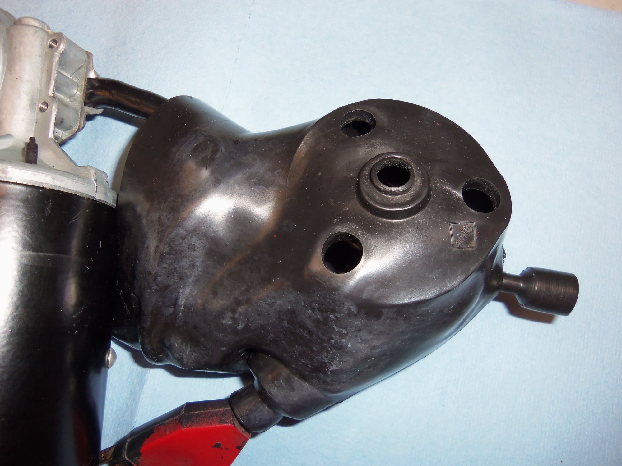
Detail of the motor mounting, spindle shaft, and crud.
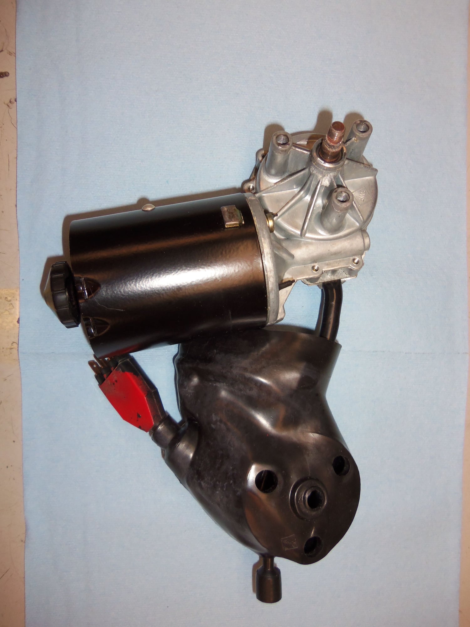
Cleaned up.
Wiper motor.
Hmmm...looks familiar.
Front side of the rubber casing cleaned up.
Backside of the rubber casing cleaned up.
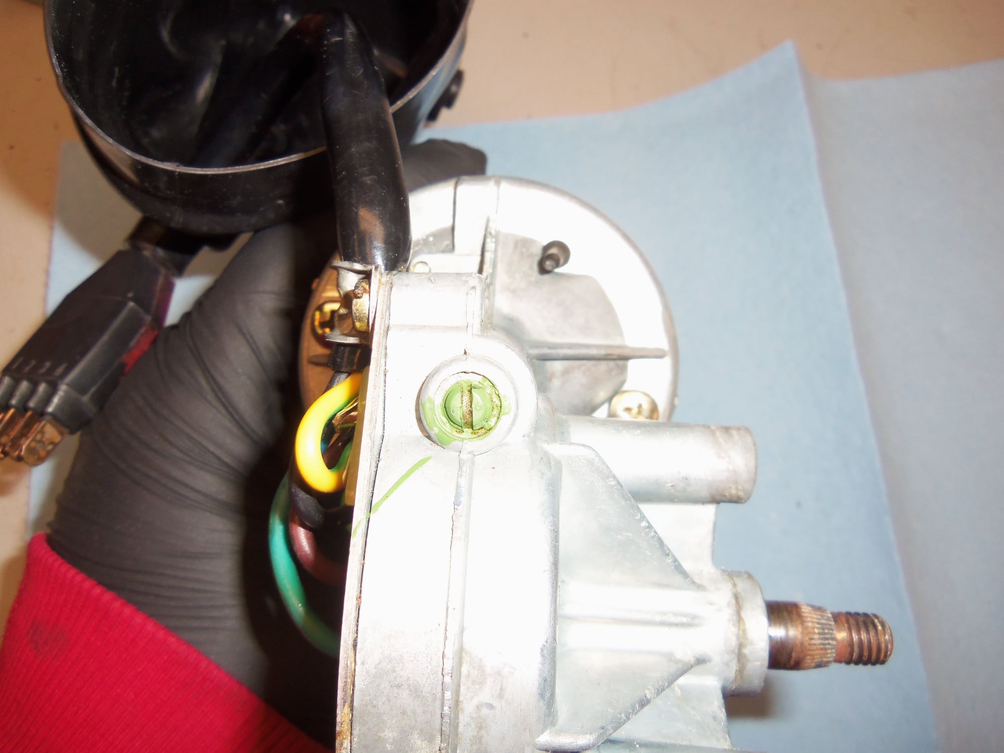
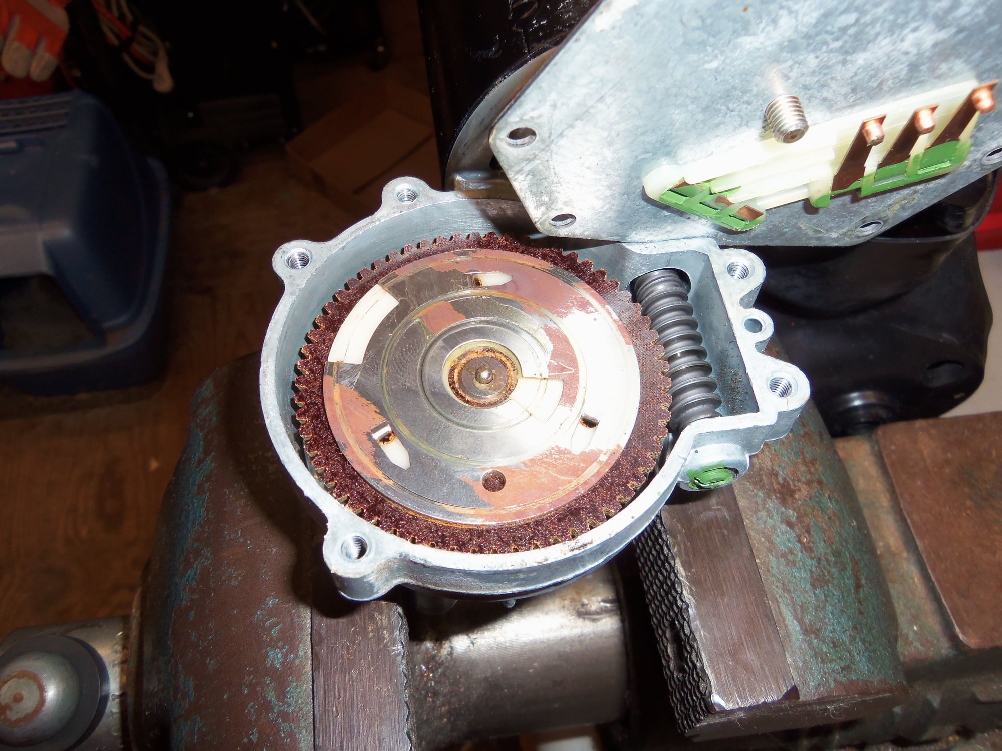
Gearbox contact wiring.
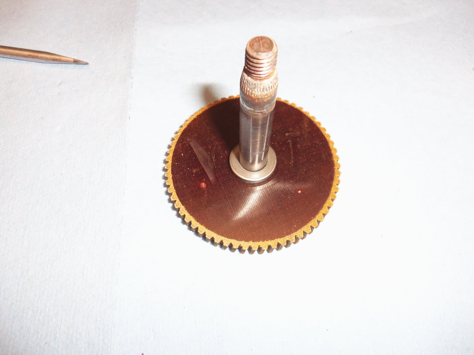
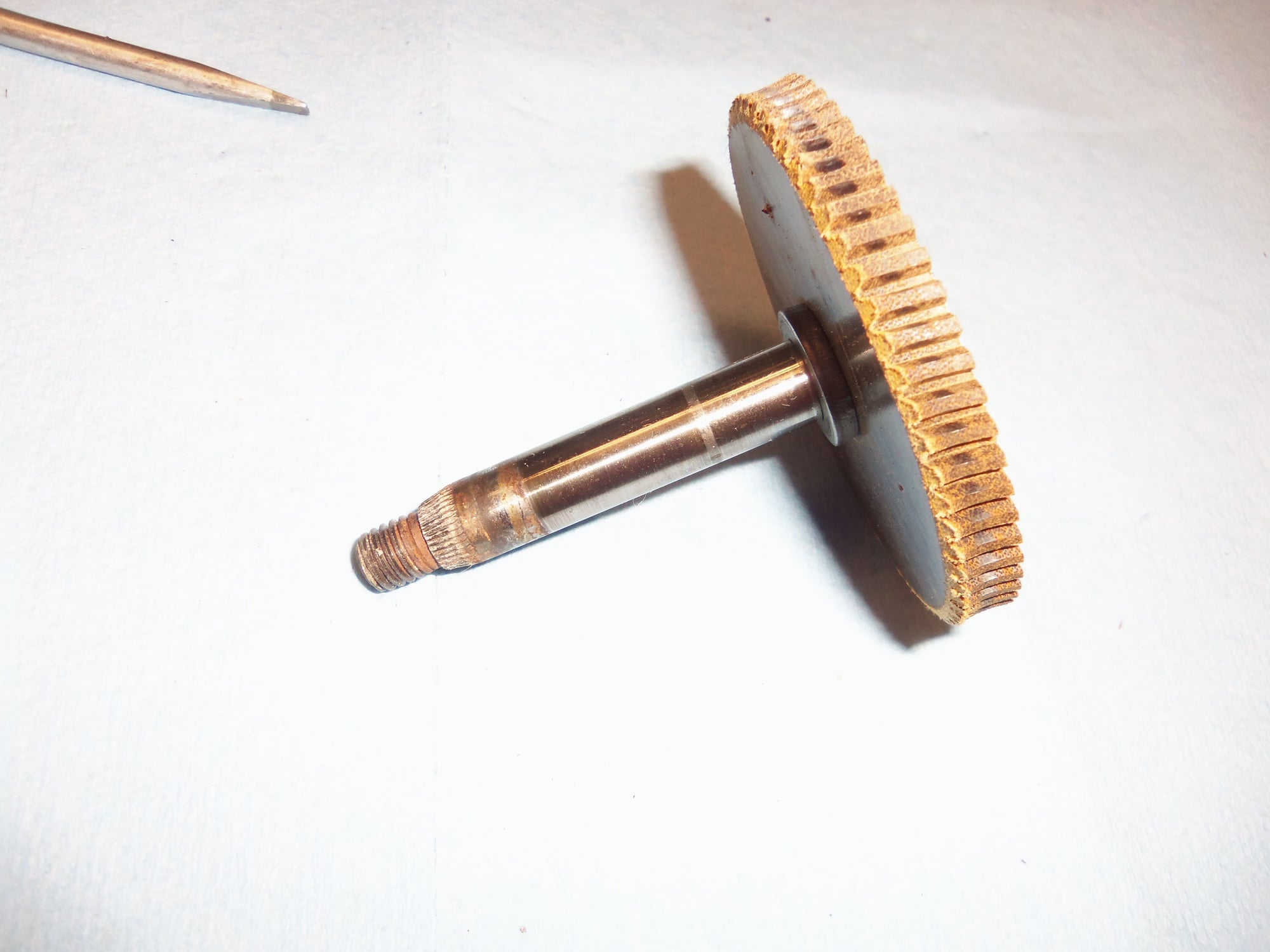
Drive spindle side of the gearbox.
Thrust pin adjustment on gearbox.
Manual adjusting ****.
Red paint is left over from the repaint in 1998.
I was concerned at this point. The motor and gearbox looked very clean, very good. I was beginning to doubt my wisdom of removing it and taking it apart. Oh well, too late now.
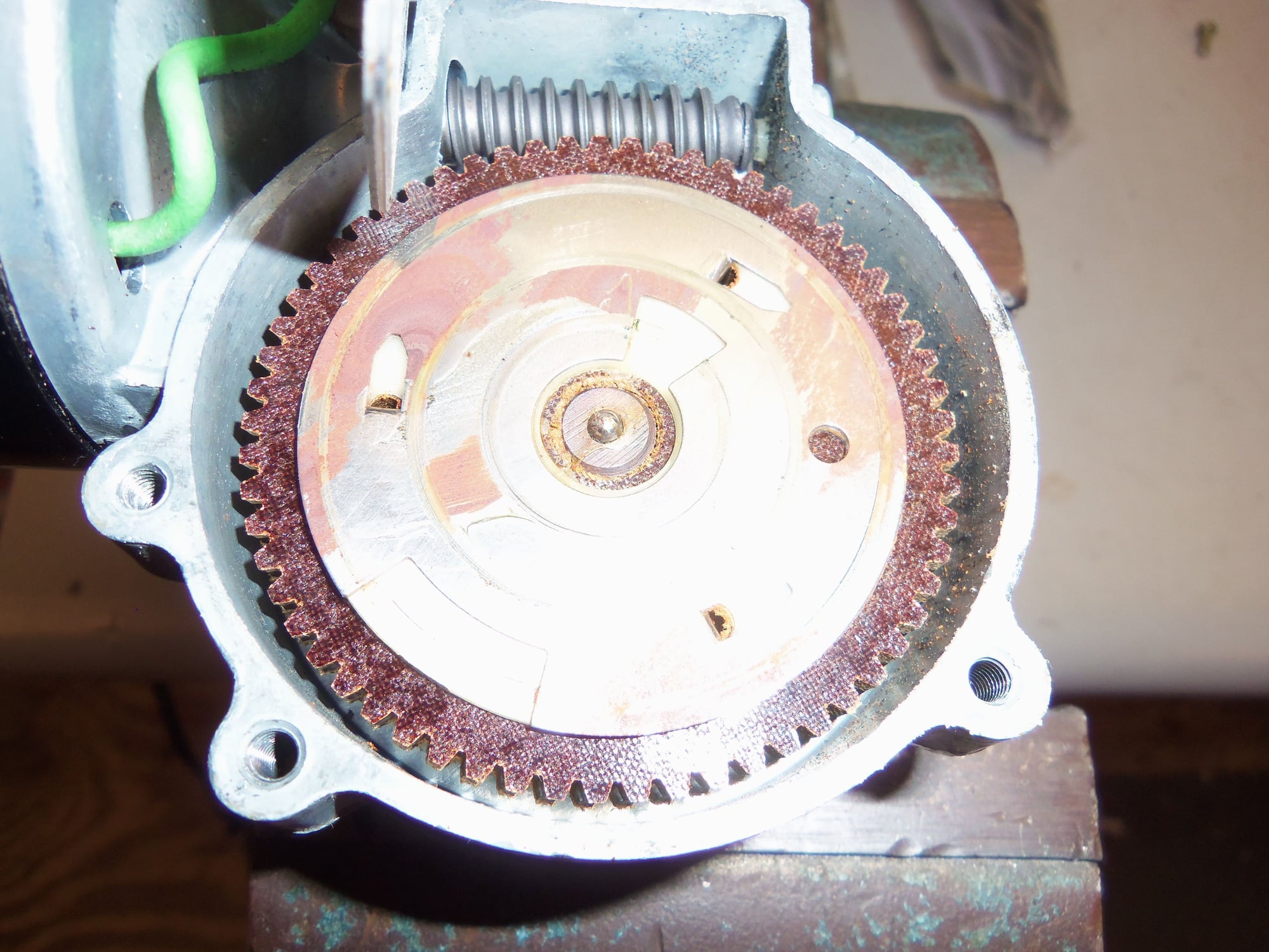
I removed the cover to the gear box, and immediately noticed two things:
There was NO grease.
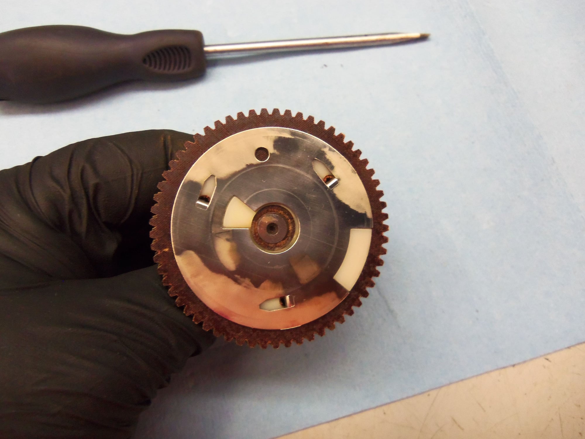
There was RUST on the contact wheel on the main gear.
AHA!!!
Thinking my way through it, I realized there was no grease because the main gear was fiber. It ran slow enough, and with a short enough duty cycle, that lubrication was not needed between it and the worm screw on the motor.
Thinking through the rust on the contact wheel took a bit longer. In a nutshell, what I think was happening is the main gear would turn until the copper contact hit the rust, and would break the circuit. This would stop the motor, just as if it had reached the proper cut out in the contact wheel.
I removed the main gear from the gearbox housing, careful not to lose the ball bearing used for thrust. I used a fine brass wire wheel in a dremel type tool to gently clean the corrosion from the contact wheel. Afterward I cleaned the contact wheel with mineral spirits. I noticed there was a thin, greasy feeling film on the contact wheel. For lack of a better idea, I replicated this with a super thin layer of dielectric grease. I cleaned all three copper contact points with DeOxit D5. None of the contacts showed any kind of damage, and the arms weren't bent.
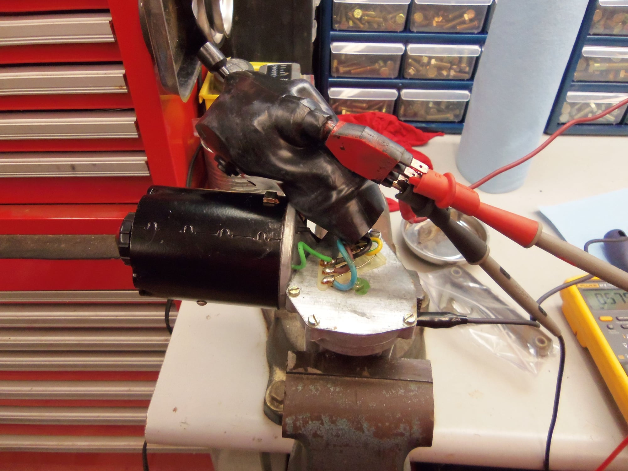
I reassembled the gearbox and jigged it up in the bench vise. My intent was to build a test rig. However. I was concerned about how to wire it up. I sorta got lost in the wiring diagram. After staring at the wiring diagram and searching threads on Rennlist, I had an 'AHA' moment. All I need is +12VDC on motor plug terminal #4 and ground on the motor casing. The motor will run. Pre '87 headlight motors only run in one direction. The cut outs in the contact wheel and the combination headlight relay controls the motor motion.
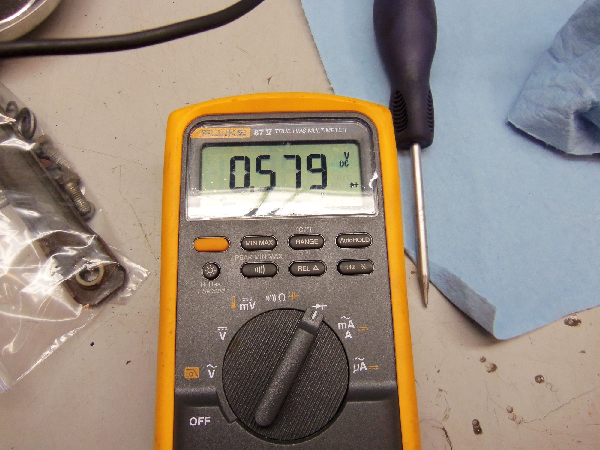
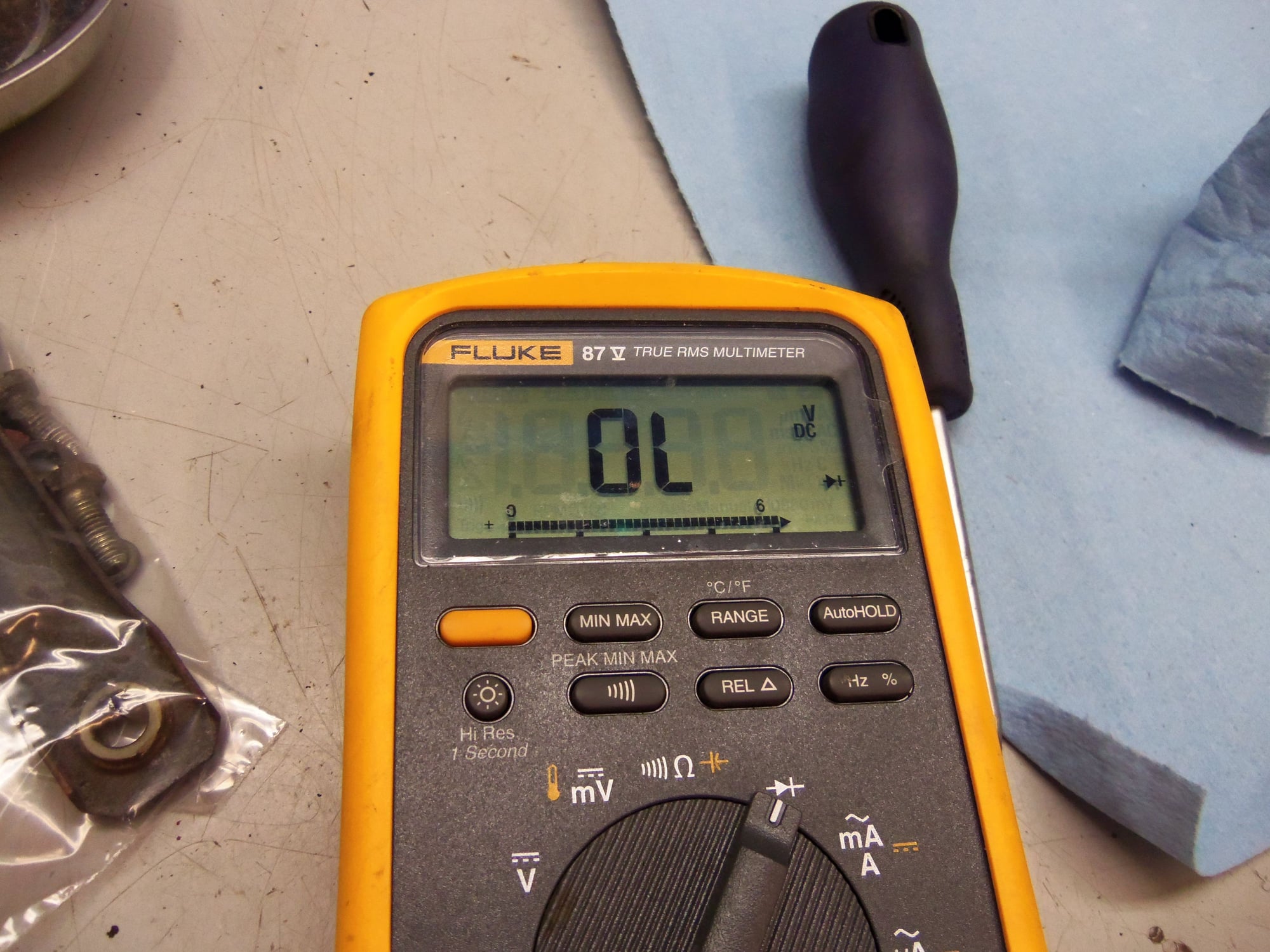
First, I checked each diode for motor terminals 1 and 2. They were good, showing 0.579VDC when forward biased, and did not conduct when reverse biased.
With the motor jigged up on the bench vise, I connected +12VDC and ground from my work bench test panel to motor terminal #4 and the casing. The motor ran fine. No funny noises, no excessive current draw.
With the motor running, I checked the diodes between motor terminals 1 and 3 and 2 and 3. I saw them cycle through conducting and not conducting. This told me that the contacts were all conducting properly, and the contact wheel was clean.
Aha! Corrosion on contact wheel.
Better shot of corrosion on contact wheel.
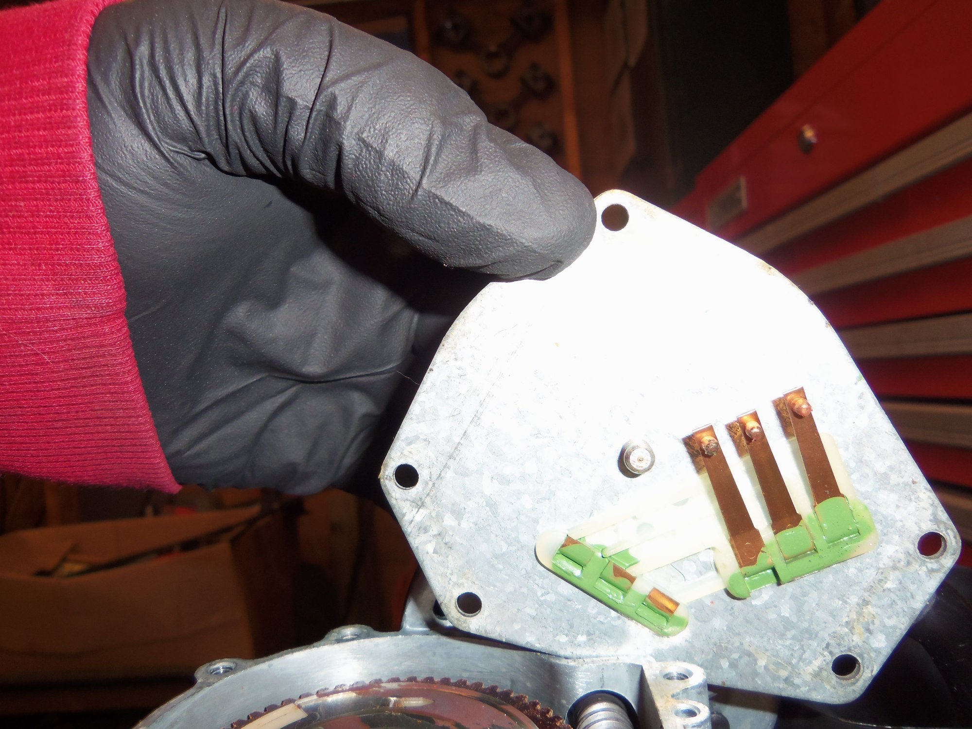
Copper contacts and arms on back side of gear case cover.
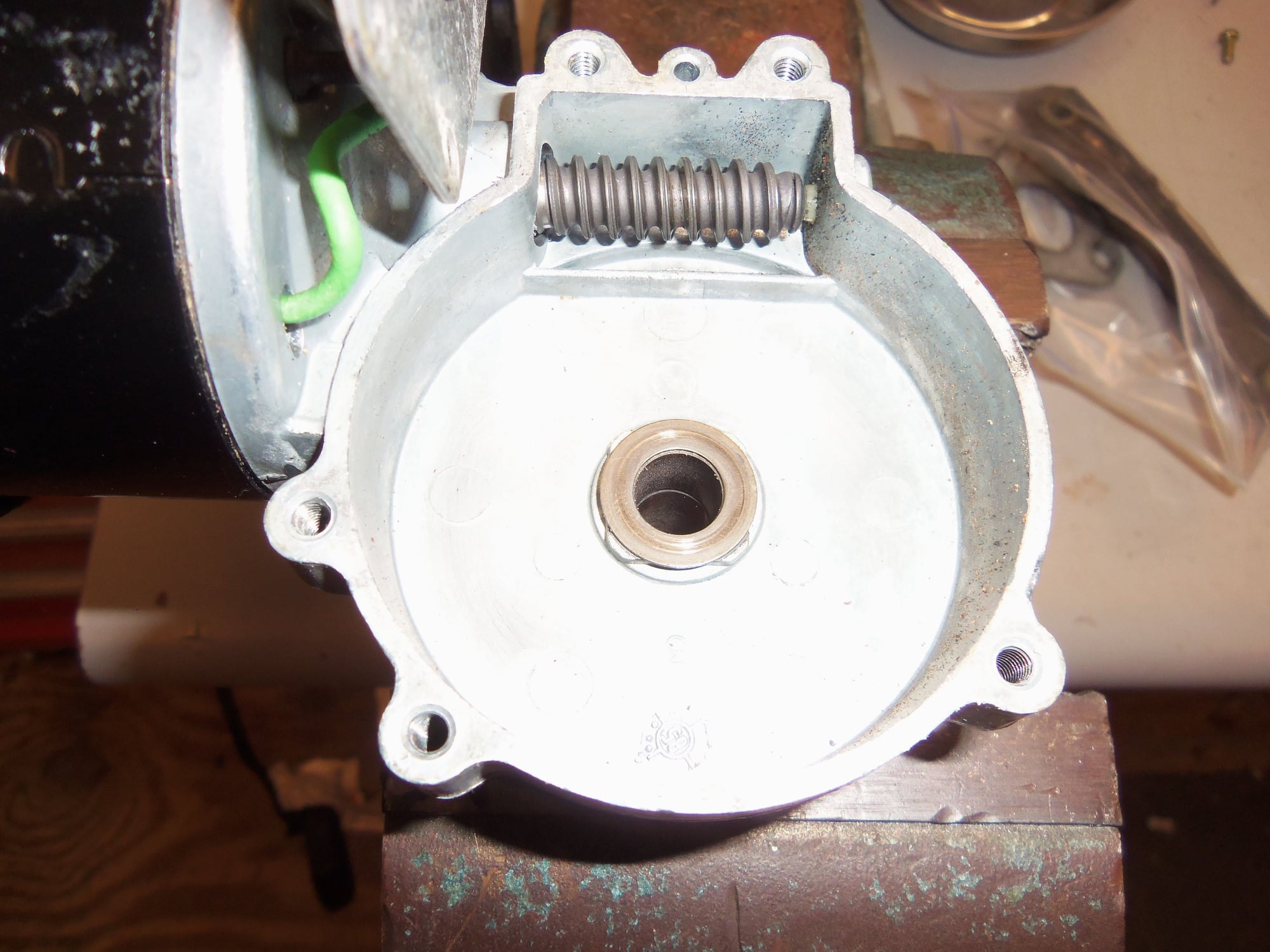
Gearbox with main gear removed.
Fiber main gear.
No unusual wear on fiber teeth.
Corrosion cleaned away.
Diodes forward biased.
Diodes reverse biased.
Motor jigged up as test rig.
Workbench test panel.
I was very pleased now that the motor worked as advertised. I reinstalled the rubber casing back over the gearbox and lower motor housing. That was only slightly easier than getting it off.
Note, based upon how well the motor ran, and how quiet it was, I elected NOT to further disassemble the motor itself. I recall the horror show that was the inside of the wiper motor...
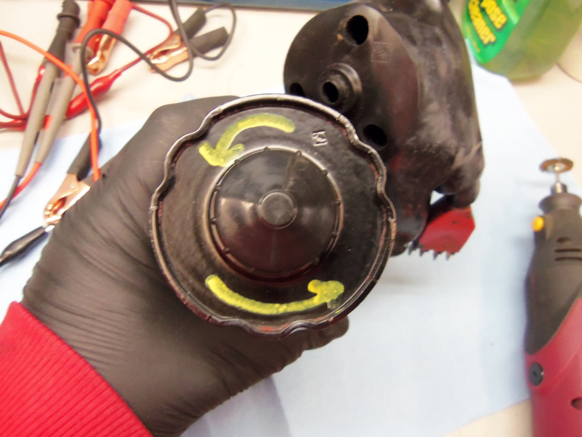
I did put a note for myself on the end of the motor casing with the manual ****. I put two yellow arrows in the counter clockwise direction. I had read somewhere that you should not turn the manual **** clockwise, as this could bend the contact arms in the gearbox. Seeing how all that operates, I can understand that. In addition, I looked in the, God forbid, owner's manual. On page 90, it talks about turning the **** to the left (counter clockwise) to raise or lower the headlights. Since I have been known to easily forget things, I put the yellow arrows on as a reminder.
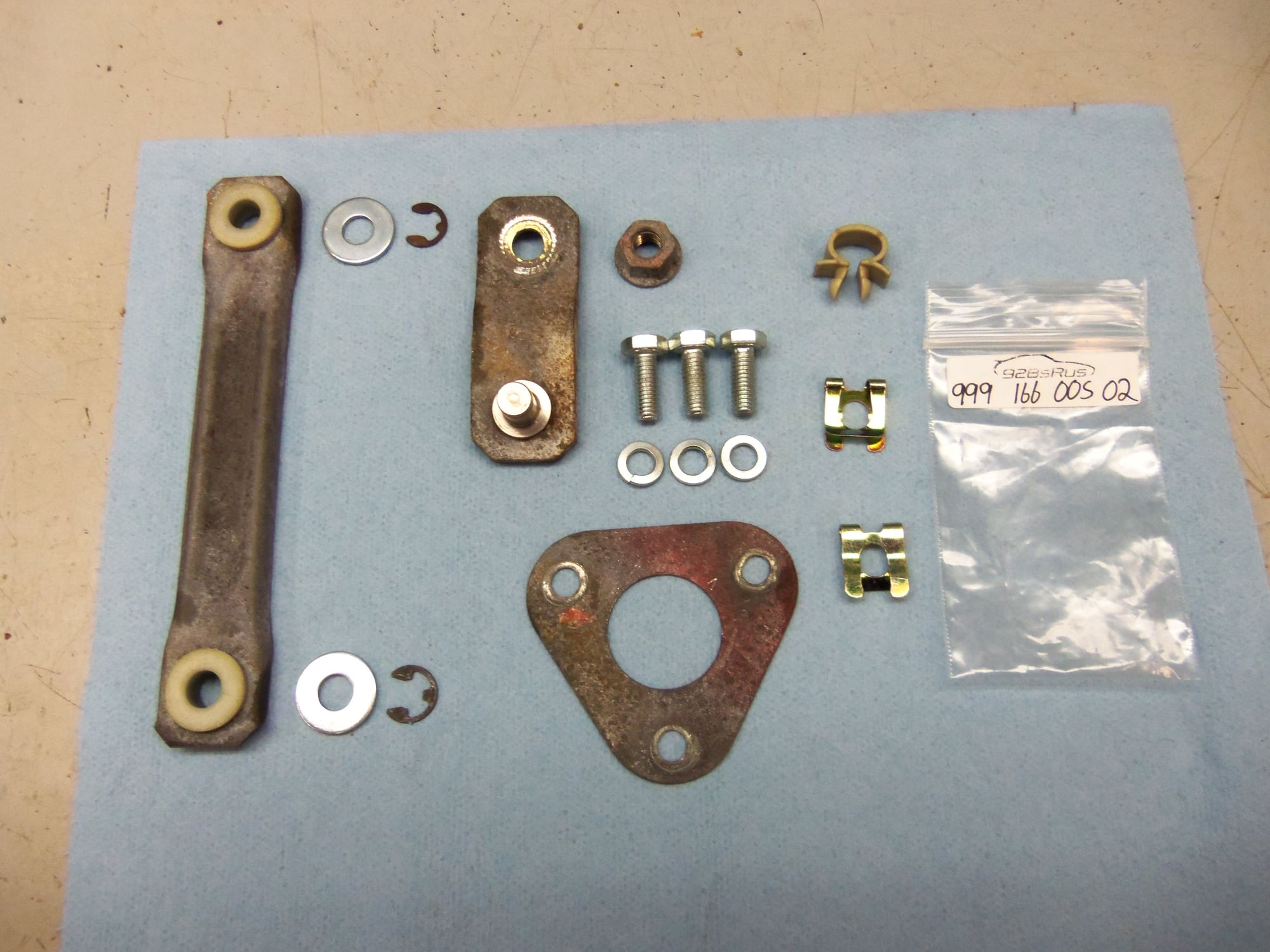
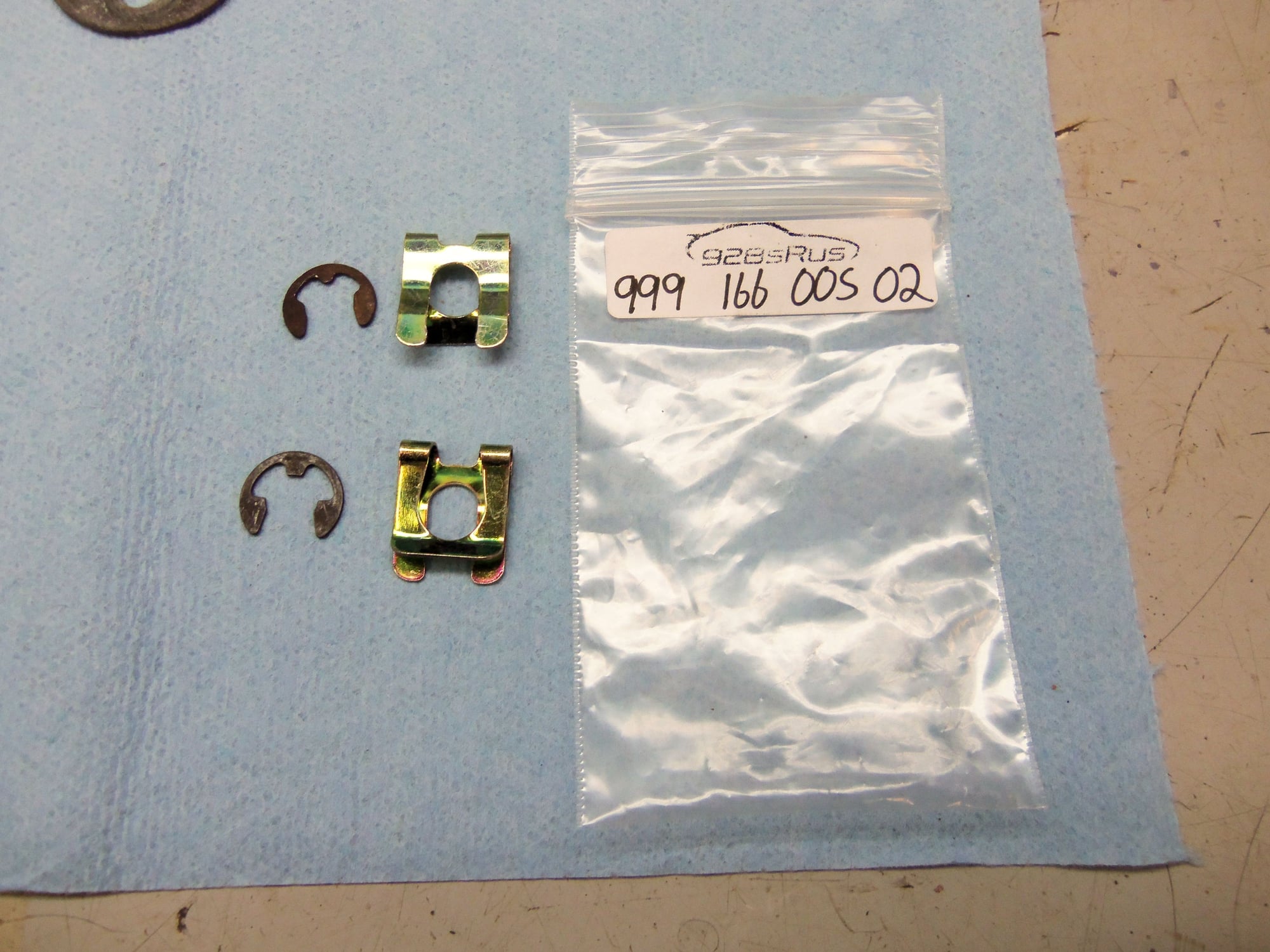
I did have a hiccup on reinstallation. Following an idea from Rennlist, I bought two of the locking clips for the automatic shifter cable, part number 999 166 005 02. These were to replace the simple E-clips for holding the linkage rod on. Yeah. They didn't fit. Just too small enough to not be able to be forced to fit. And its too late, as Daniel5691 gave all his cool headlight clips away already. Grrrr...back to the drawing board.
Seth-don't-be-dumb arrows for the manual ****.
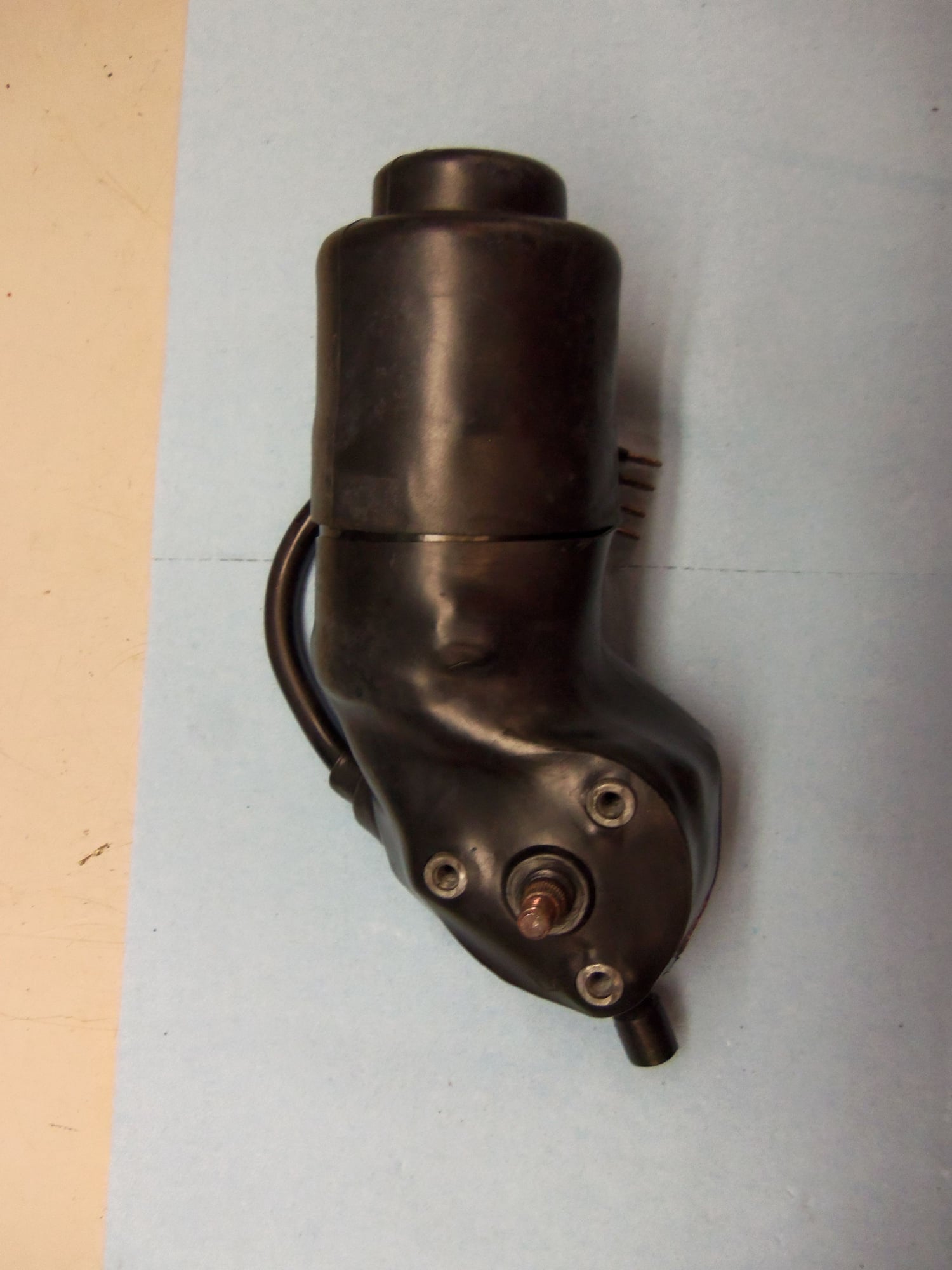
Cleaned up and reassembled.
Ready to be reinstalled.
Small parts cleaned and ready. New mounting hardware as well.
The shifter cable clips that don't quite fit.
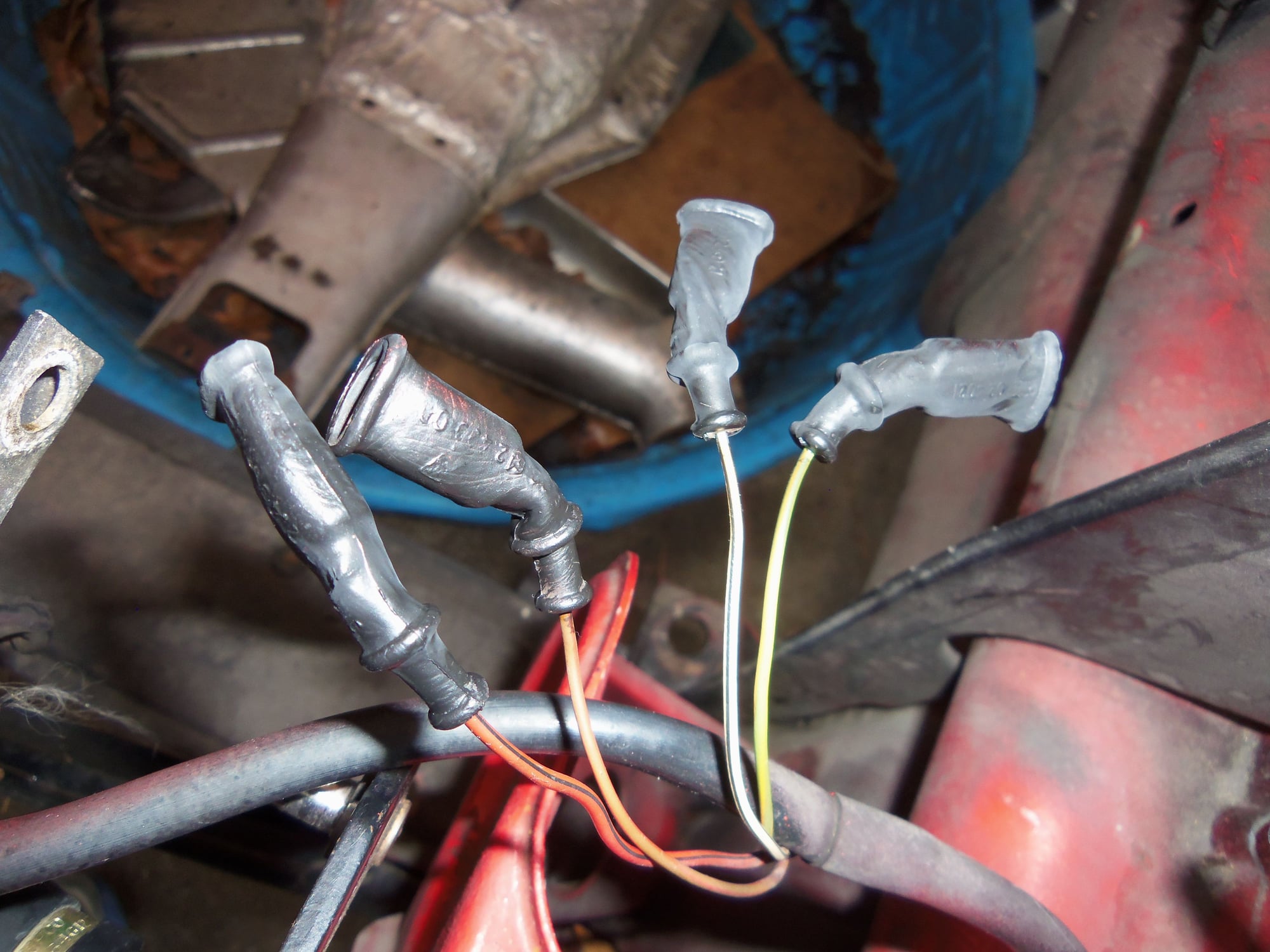
Prior to reinstalling the motor and linkage. I cleaned up the wiring and such with mineral spirits. The terminal boots were a little rough. I 'painted' them with liquid electrical tape, for lack of a better idea. Same thing for the boot for the radiator temperature switch. I am well aware that the terminal boots and such are readily available. However, they require the terminal to be cut off the wire to fit over it. All the terminals on my wiring are in good condition. So, I elected not to replace the boots.
I routed the radiator switch harness back down the front structure and secured it with the white clip. That took more dexterity than I expected.
I reinstalled the motor, but left the crank arm off. With power back on the Red Witch, I turned the headlights ON and then OFF from the pod switch. This way, I knew the headlight motor was stopped in the 'DOWN' position. I reinstalled the crank arm lined up with the match marks I made earlier. Then, it was just a matter of adjusting the motor up a little bit to allow the linkage arm to fit.
Then, with more than a bit of trepidation, the test run. The headlights worked! The pods cycled up smoothly and the lights came on. The lights went off and the pods cycled down smoothly.
I am more than a little pleased to get this fixed and put to bed!
Wire terminal boots 'painted' with liquid electrical tape.
Wires back on the correct plug terminals.
Boots pushed back down, all is good.
Radiator temperature switch boot, also 'painted' with liquid electrical tape.
Terminals for the temperature switch.
Motor and retaining plate reinstalled.
Motor reinstalled, linkage in the UP position.
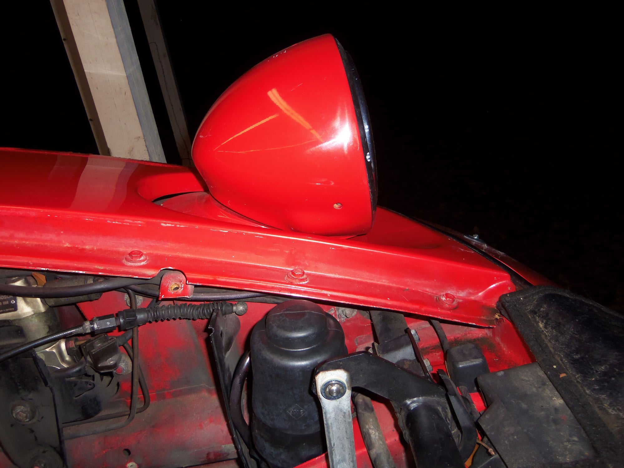
Pod up!
YAY!!! Lights are up and work.
Alright, for those of you still reading, full disclosure:
This was a waste of time! Thinking back over what all I had to do, and why I had to do it, I probably could have fixed the headlights by cycling the motor by hand a couple of times. The corrosion on the contact wheel was causing the relays to drop out too soon. If I had turned the **** several times, the contacts would have likely cleaned the corrosion from their paths on the contact wheel. This would have restored the proper operation of the relays and such.
So...if the headlights on your pre '87 928 are not fully raising, try turning the manual **** a few cycles. Can't hurt...
The last time the engine in the Red Witch ran was October 2016. I added 10 gallons of fresh 93 octane gasoline treated with Stabil 360 and SeaFoam somewhere before then. So...the Red Witch has half a tank of almost 2 year old gas.
This has really been bugging me recently. Prior to adding the treated gas, I drained the fuel tank by pulling off the hose from the strainer to the fuel pump. That actually was a bit of a pain in the a$$.
So, in true Seth form, I overthought the entire process. And did it.
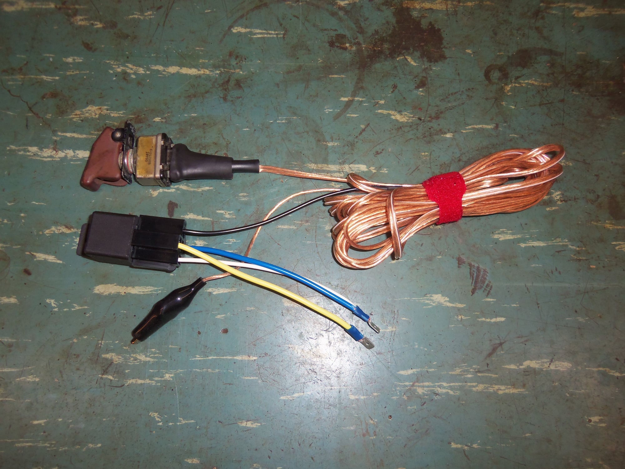
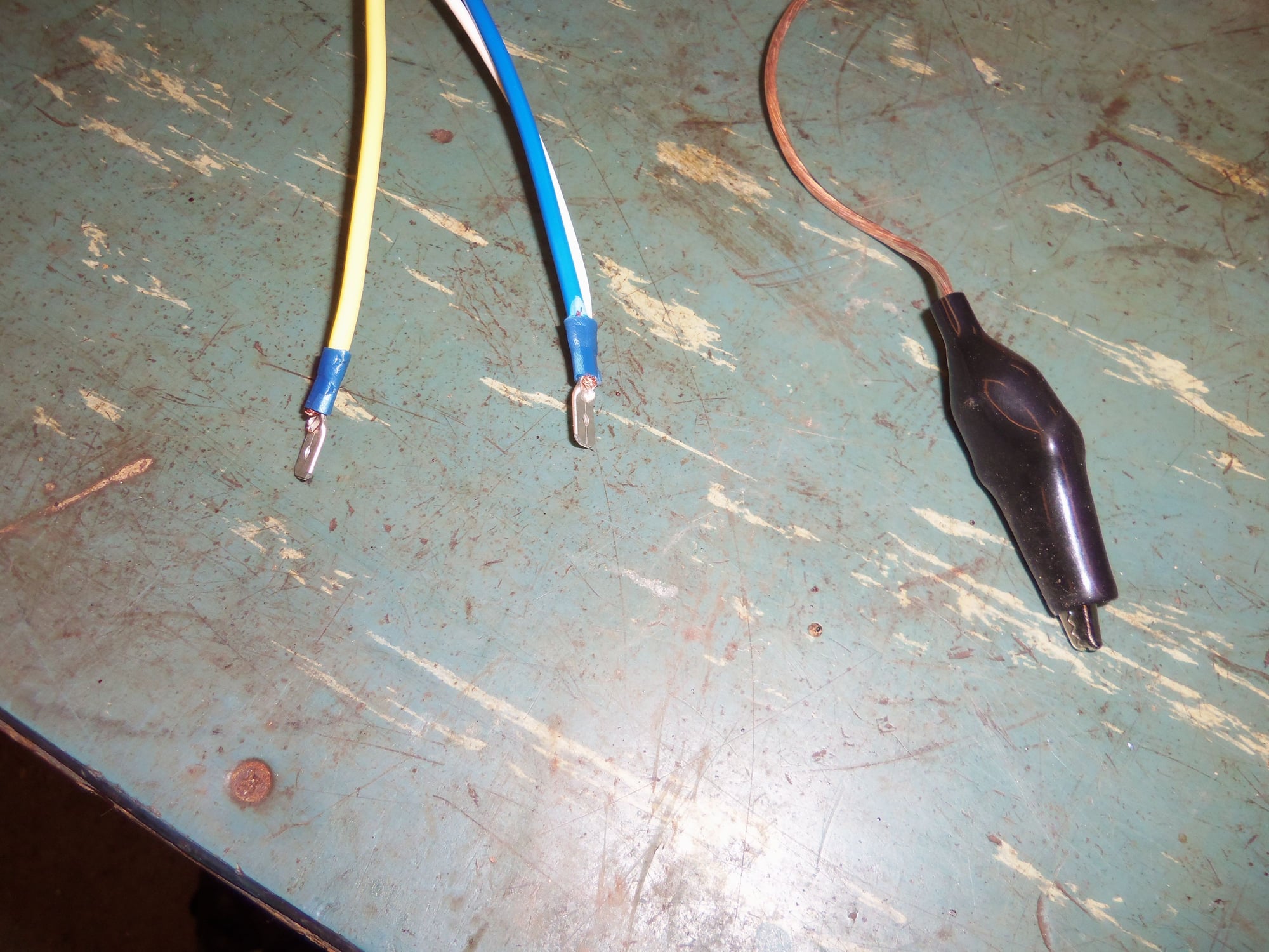
I fabricated my own version of a fuel pump jumper using a mil-spec toggle switch, a common SPST relay, and alot of wire. I didn't want to have something like 10 feet of 12 gauge wire for this, so I used a relay. I bought a bunch of relays and matching short harnesses in the past. I put spade terminals on the ends of the wires for 85, 30, and 87. Terminal 86 went out to 10 feet of 18 gauge speaker wire to the aforementioned switch. From the switch, it came back to the speaker wire, then to an alligator clip. The alligator clip was then attached to one of the grounding points above the CE panel.
I cheated and put wires 85 and 30 in the same spade terminal, to be connected to terminal 30 in the socket for the fuel pump relay in the CE panel. This way, all I have to do is connect the battery to provide power to the relay and pump. The switch provides the ground to energize the relay and provide power to the pump.
I used 10 feet of wire between the switch and relay to give me enough room to be at the fuel pump or the front of the car with the switch.
Fuel pump relay jumper switch, relay, and 10' of wire.
Blue (30) and white (85) crimped together in the same spade terminal to go into socket terminal 30. Yellow (87) goes to socket terminal 87. The black alligator clip comes from (86) via the switch.
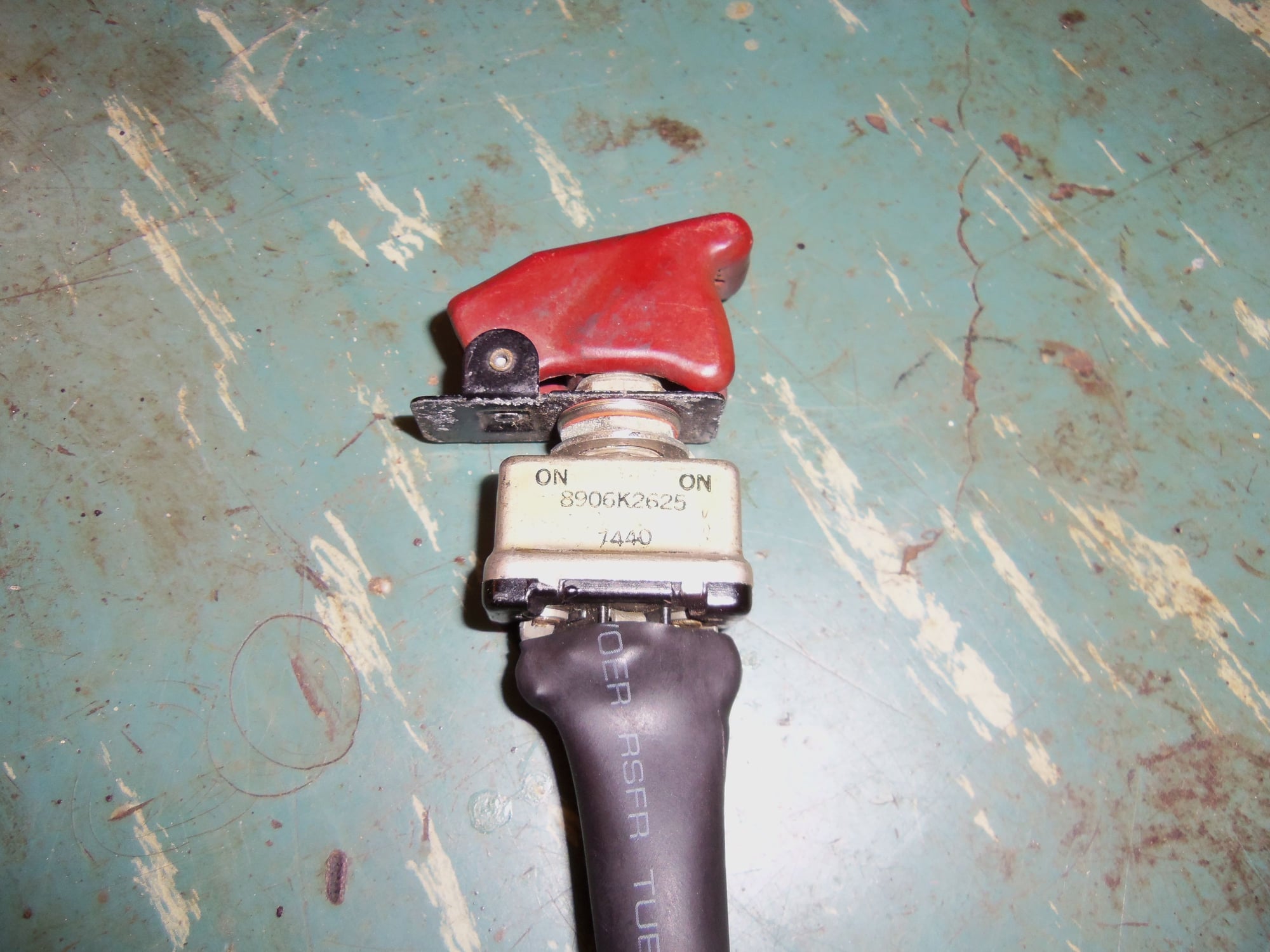
Mil-spec toggle switch and safety-close-cover I, uh...aquired, while onboard the ship. Cover closed, toggle in OFF position.
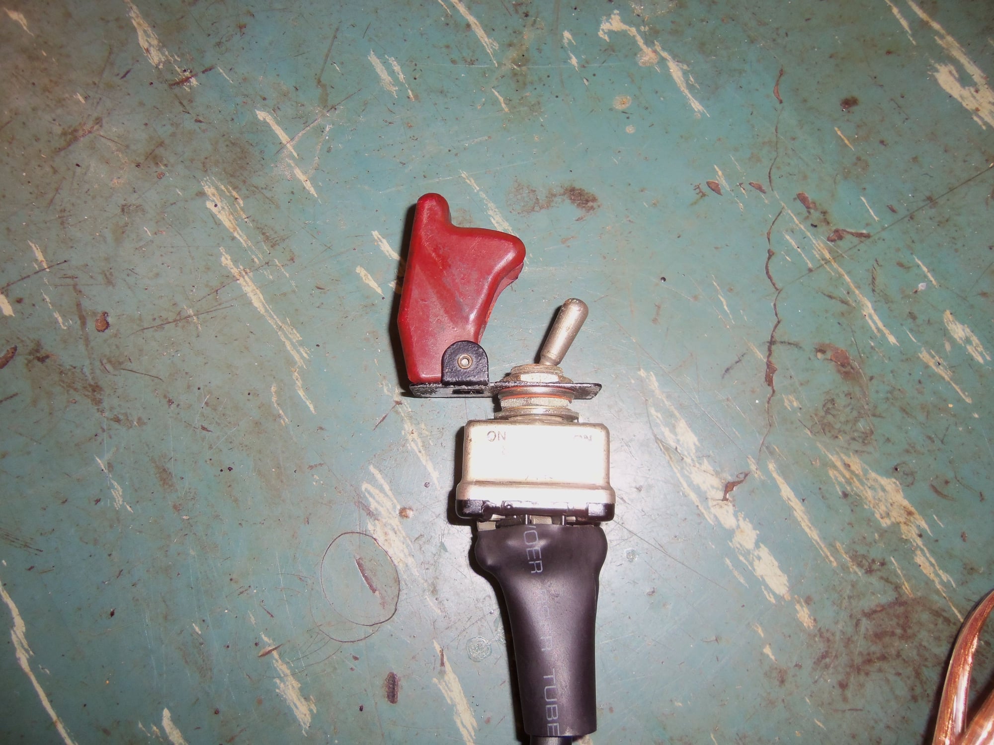
Cover open, toggle in OFF position.
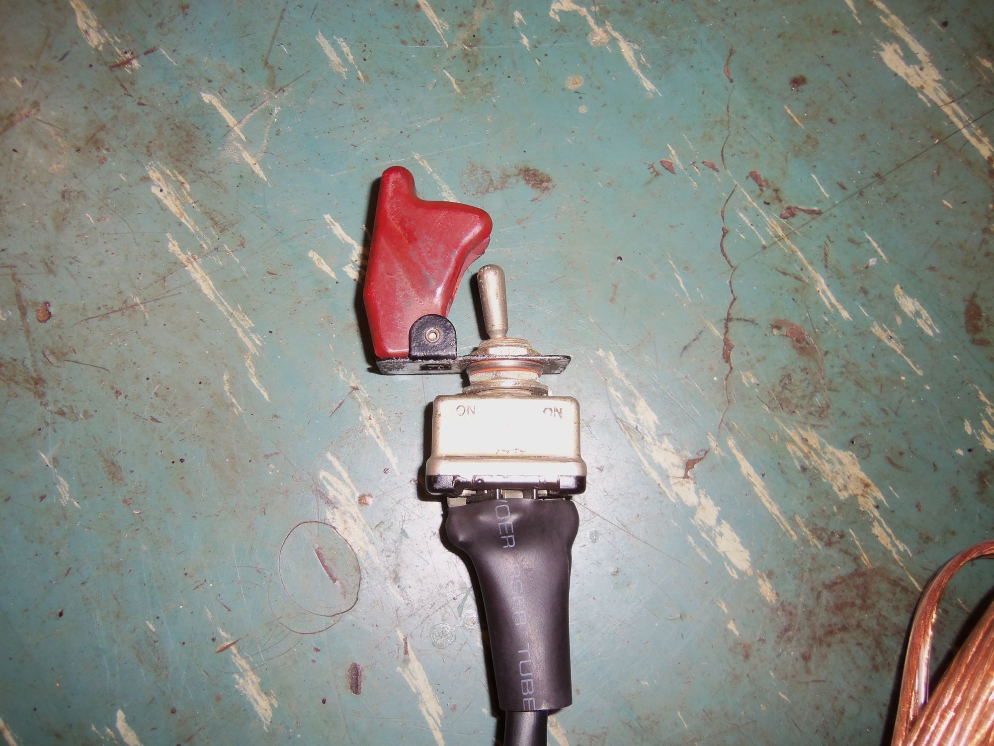
Cover open, toggle in ON position.
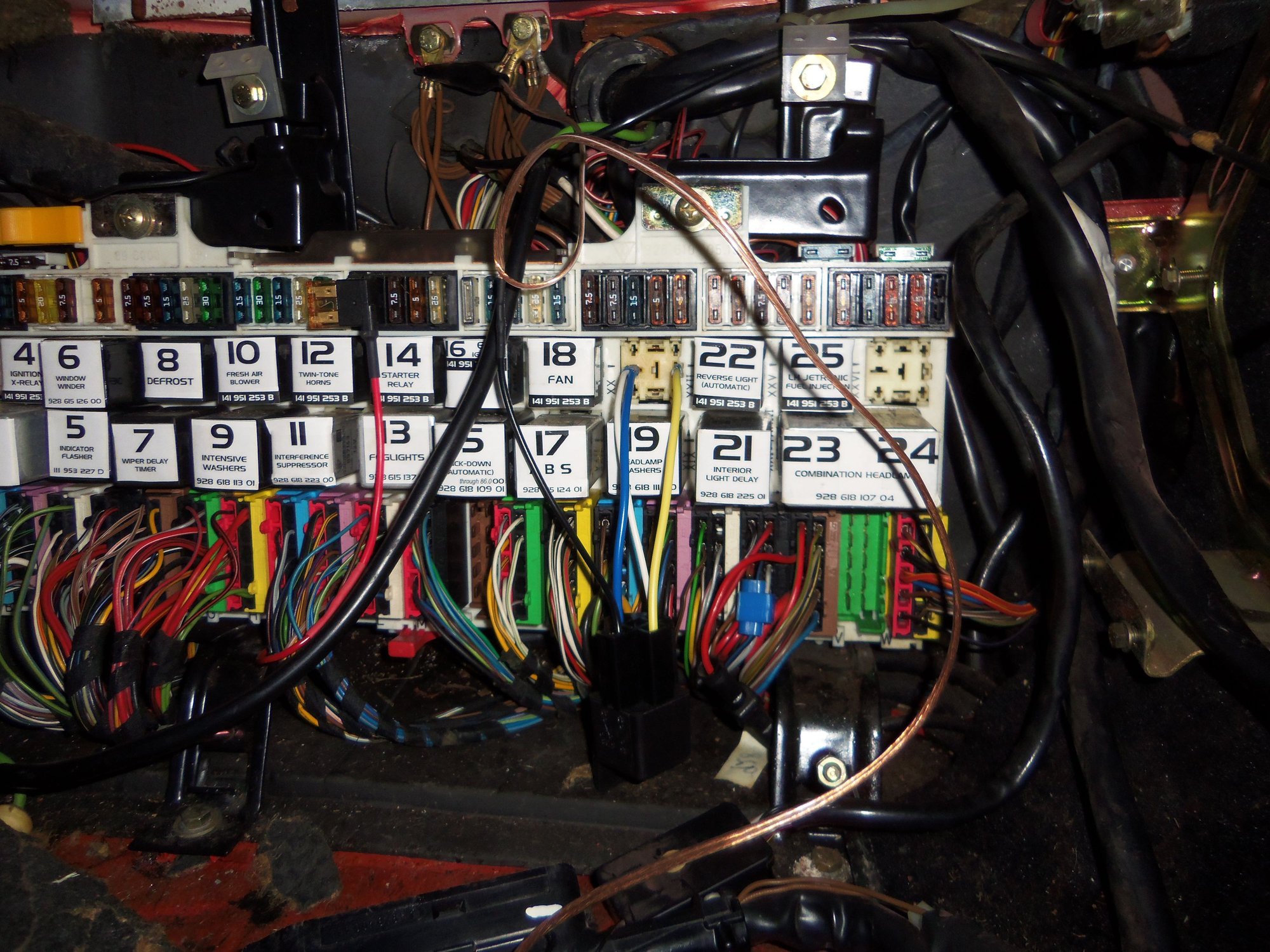
Relay connected to fuel pump relay socket in CE panel, black alligator clip attached to grounding point above CE panel.
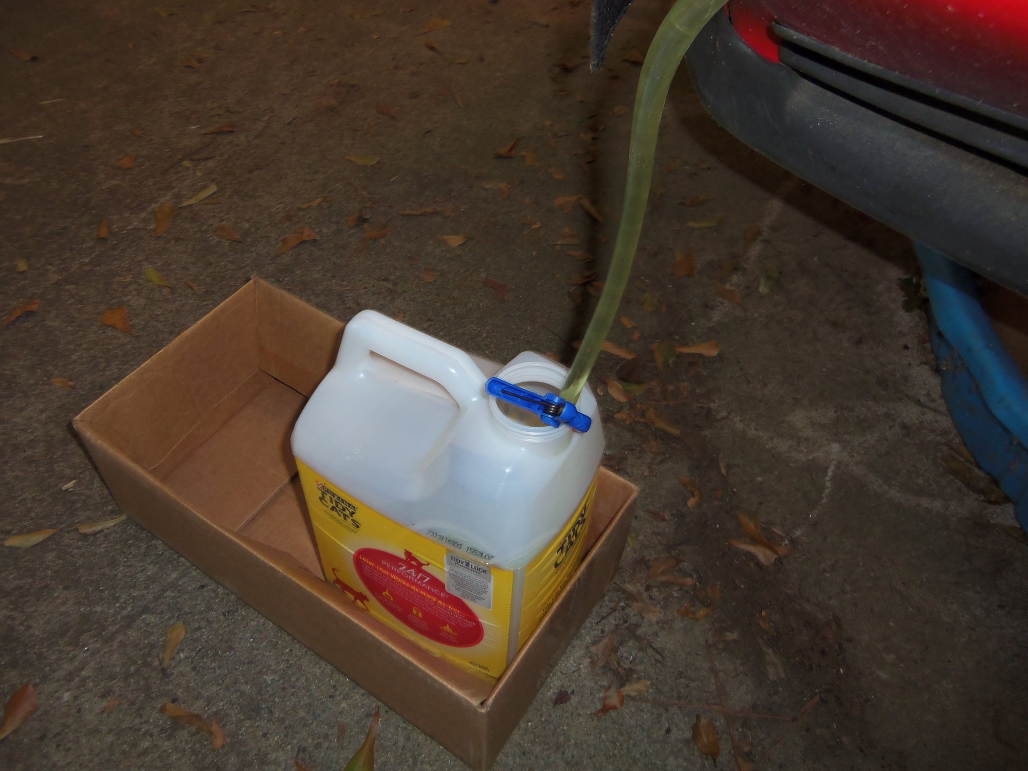
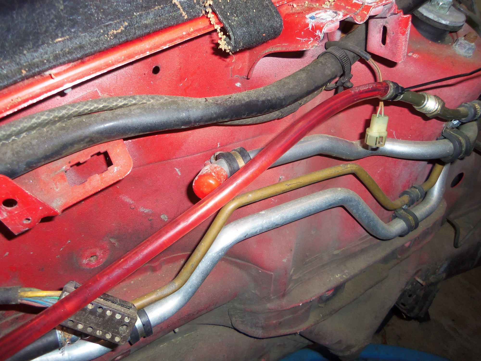
I connected a clear flexible hose to metal fuel supply line on the passenger's side inner fender. I ran the hose down to one of several empty kitty litter jugs. I held the line in place with a plastic clamp. With the switch laying on the fender cover near the nose, I was able to pump fuel and watch the level in the kitty litter jugs. Though a bit slower than I expected, this worked out quite well. The fuel did not look super hateful, but I am not trusting it.
I will admit to some relief at hearing the fuel pump quietly whirring away merrily. It is a new pump, but has not run since October of 2016.
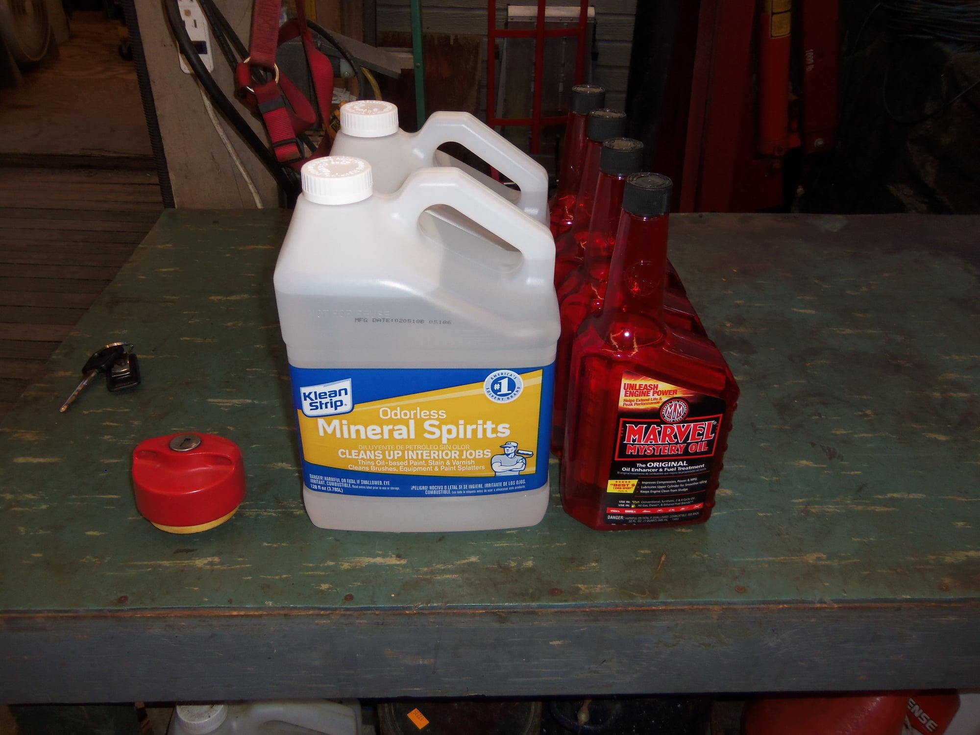
After the fuel pump lost suction, I added two gallons of mineral spirits to the fuel tank. In my mind, the mineral spirits would help clean any skanky fuel out of the strainer, pump, check valve, filter, lines, etc...
After the fuel pump lost suction with the mineral spirits, I added a gallon of Marvel Mystery Oil. In my mind, this would help 'pickle' the strainer, fuel pump, check valve, filter, lines, etc...
I ran the pump until I saw a steady stream of red fluid in the clear hose. I pumped maybe less than a quart of it out. So, there should be at least half a gallon of Marvel Mystery Oil sitting in the bottom of the fuel tank. Since the fuel is gravity fed into the pump, the pump should be full of MMO as well. I am banking on the outlet check valve on the fuel pump to keep the filter and fuel lines full of MMO.
Was all of this blessed overkill, and possibly useless? Probably. Am I happy? Definitely.
Fuel pump jumper switch sitting in close reach on the fender cover.
Clear flexible hose connected to metal fuel supply line. Currently pumping out old gasoline.
Other end of hose goes into one of several kitty litter jugs, secured with plastic clip.
Two gallons of mineral spirits for cleaning, one gallon of Marvel Mystery Oil for 'pickling'.
Steady stream of red MMO in the clear hose. Time to quit pumping.
On a semi-funny side note, once I was done pumping the MMO, I checked the fuel gauge. The low fuel light works.
Orange 'Low Fuel' light glowing cheerfully.
This should keep the fuel system OK until I reinstall the engine and the rest of the fuel components.
Seth, can you pass along the bearing information. 2 of my 4 cars wiper motors are in similar condition.
Hi Kevin!
Gladly! I put a ceramic bearing in, number 6002-2RS HB-Ceramic. I got it off ebay in 2016. It works just fine.
Please go to this thread for the horror show that was my wiper motor:
NOTE: Keep reading down past the AC work to see more of the wiper motor photos and descriptions.

 02-14-2018, 12:24 AM


 ----> http://dai.ly/x359dd <----

