When you click on links to various merchants on this site and make a purchase, this can result in this site earning a commission. Affiliate programs and affiliations include, but are not limited to, the eBay Partner Network.
Last week, when I put power back on the Red Witch, the headlights did not want to work properly.
When I turned the **** to 'headlights', the pods only raised halfway. I could hear clicking coming from the headlight relay. When I turned the **** back to 'off', the headlights briefly illuminated then went out, then the pods lowered back down.
The pods parked in the proper position.
I tried this a few more times. Then, the headlights worked as advertised. Pods raised to the full up position, then the headlights illuminated.
Several more tests showed functionality was restored.
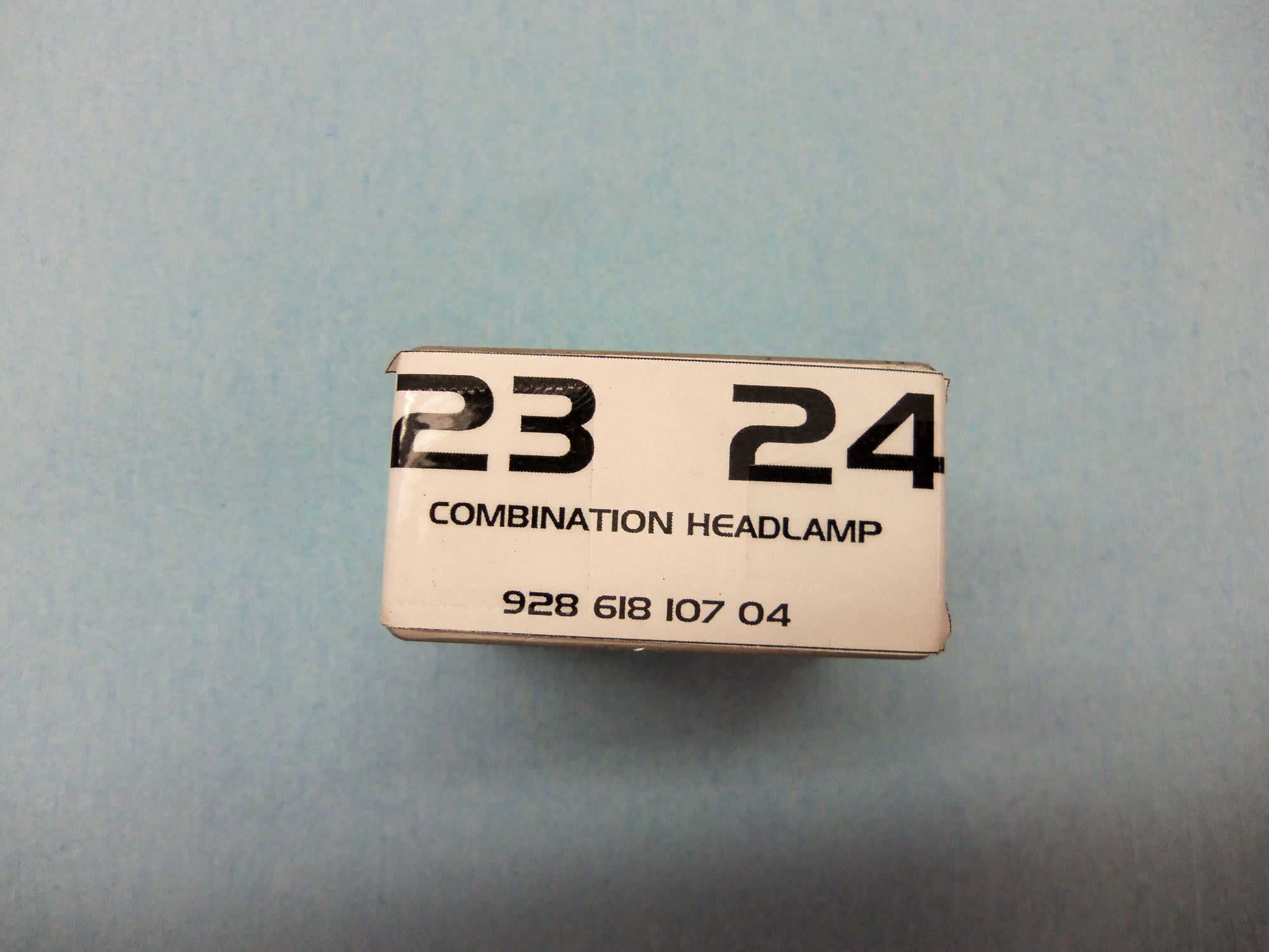
Hmmm...searching Rennlist brought up the headlight relay several times. To my knowledge, this relay is original on the Red Witch.
So, what do I have to lose by cleaning it? Other than a really expensive relay...
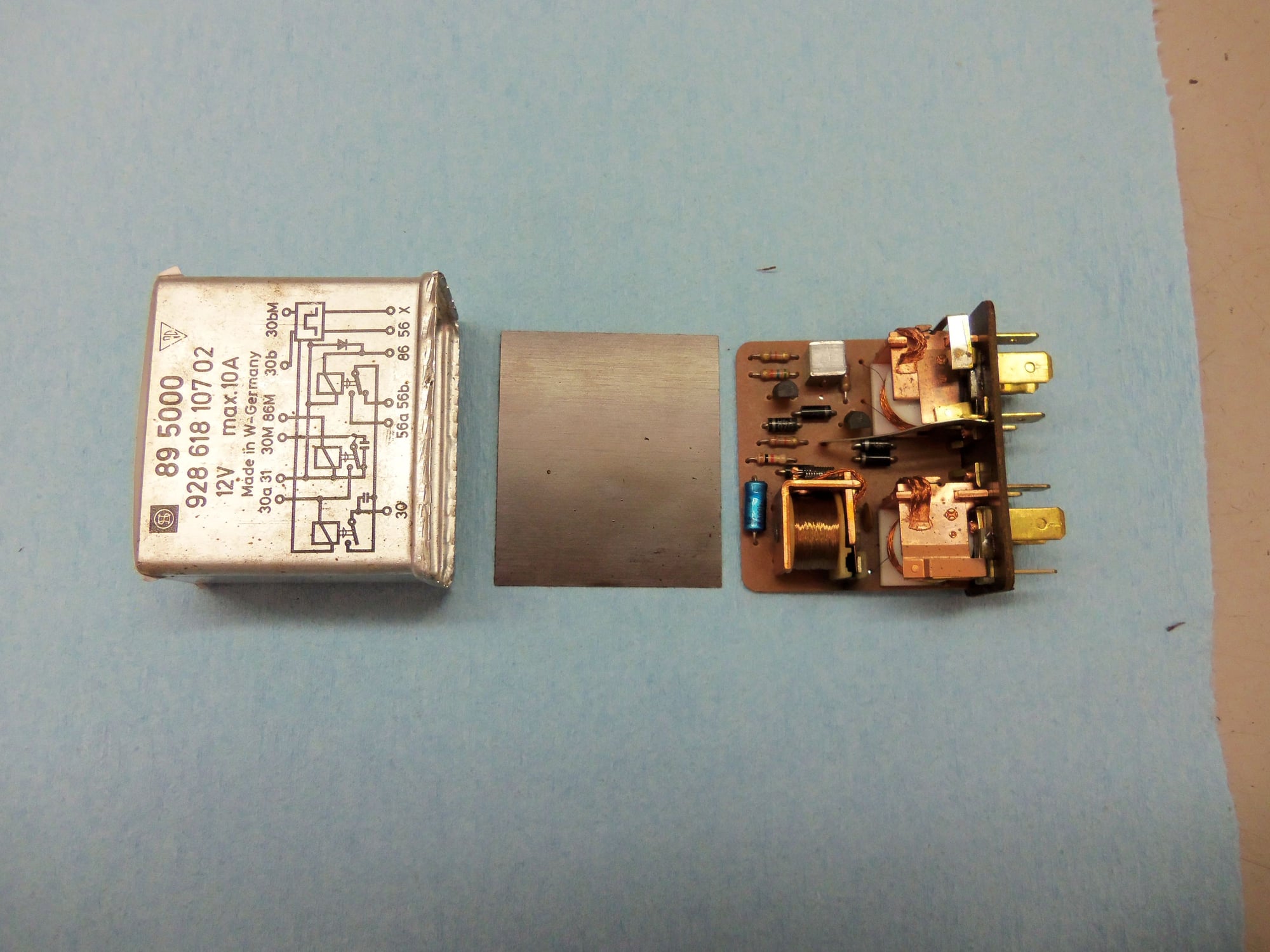
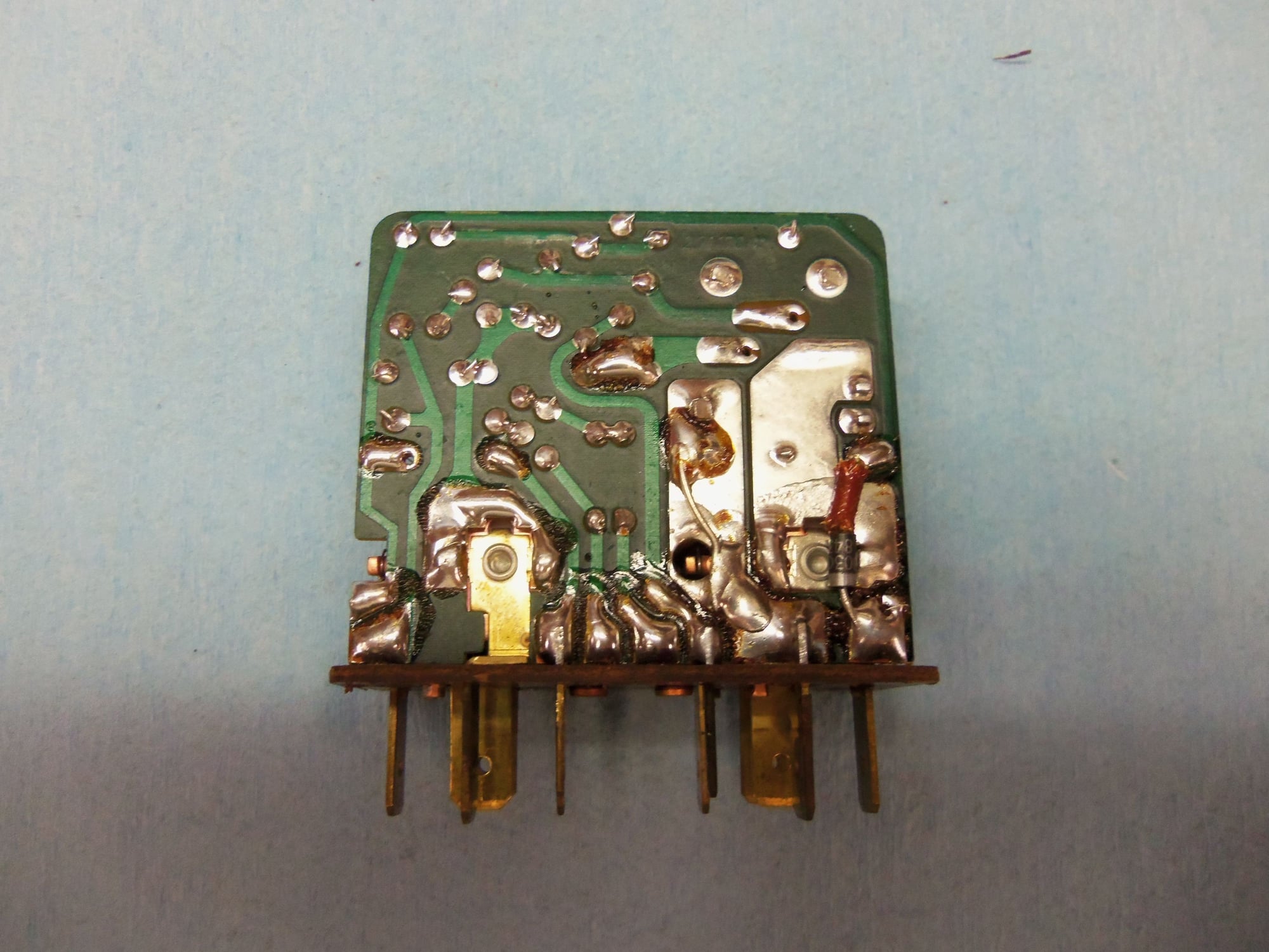
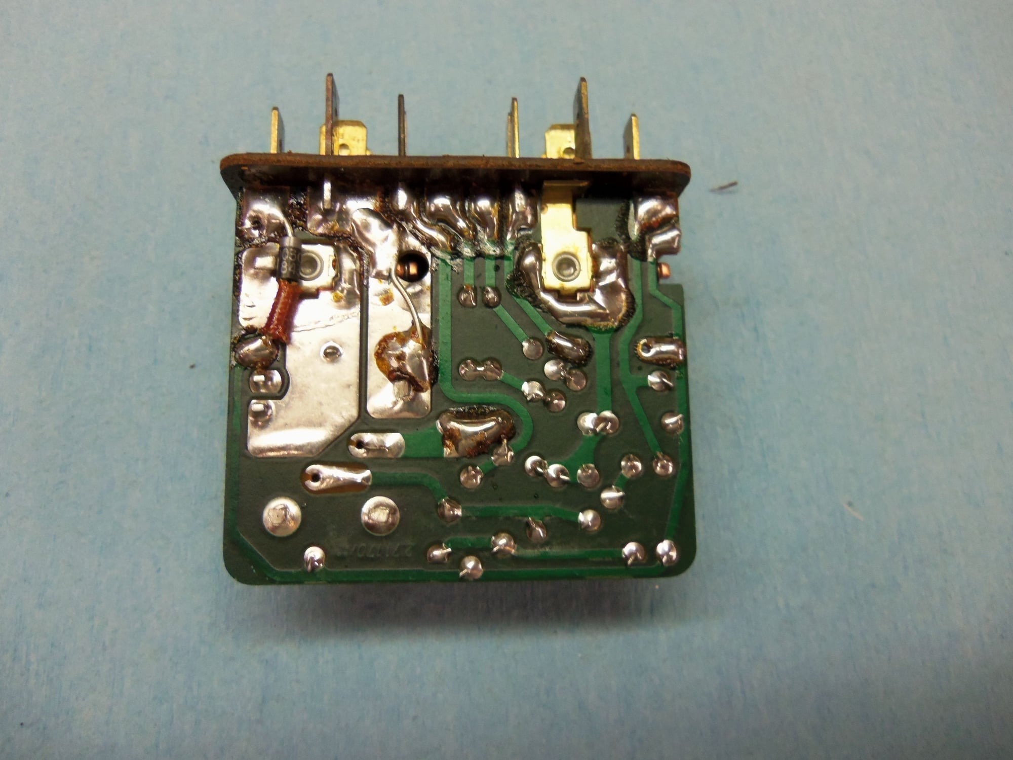
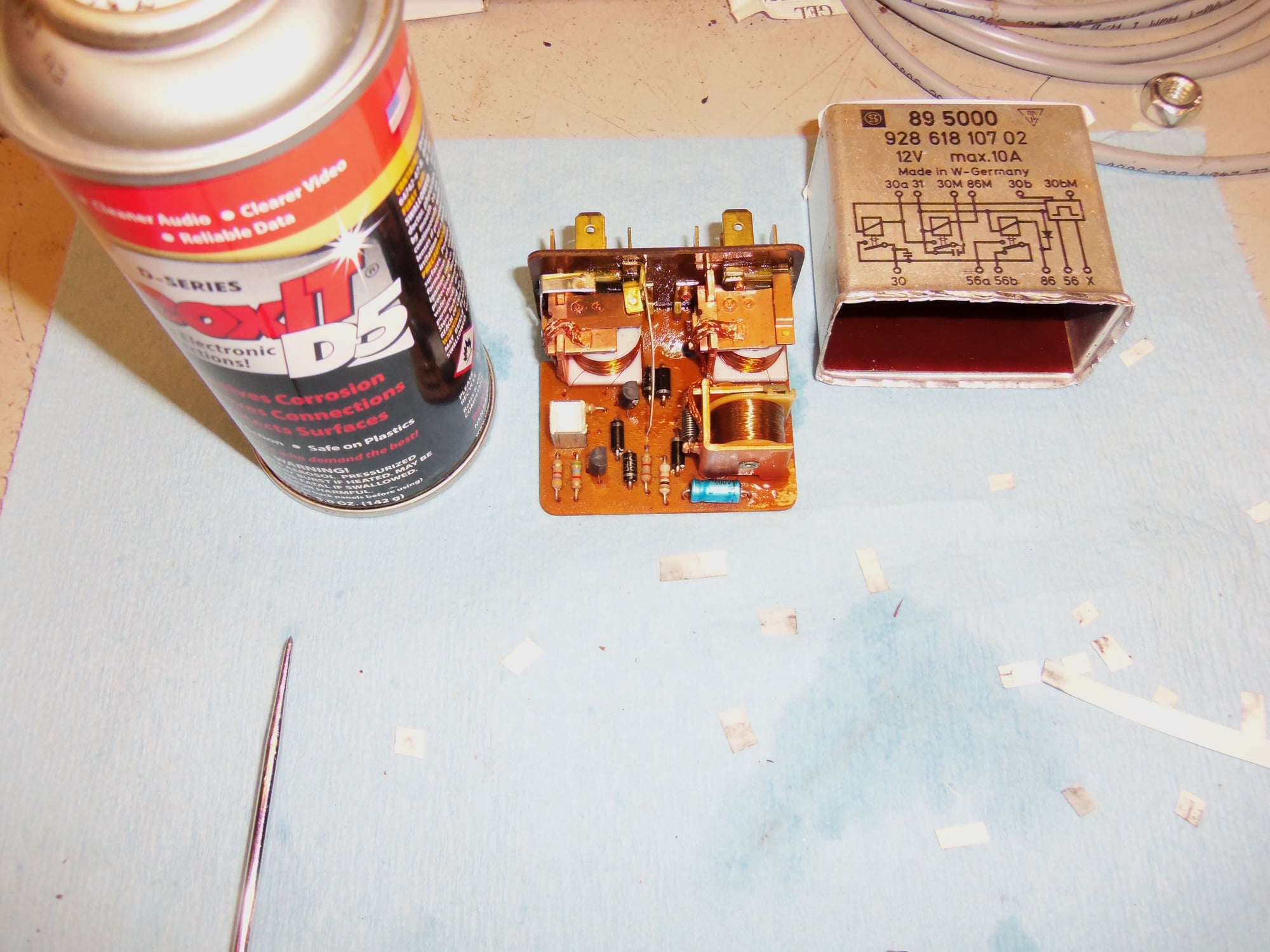
I was able to gently open the crimped end of the aluminum casing. Inside, I found the circuit board with the three relays, and supporting components.
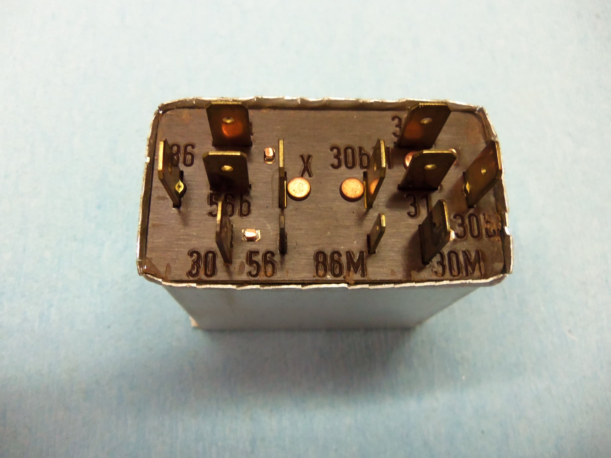
Note: I got the relay labels from this Rennlist post:
Aluminum housing, insulating plate, and relay assembly.
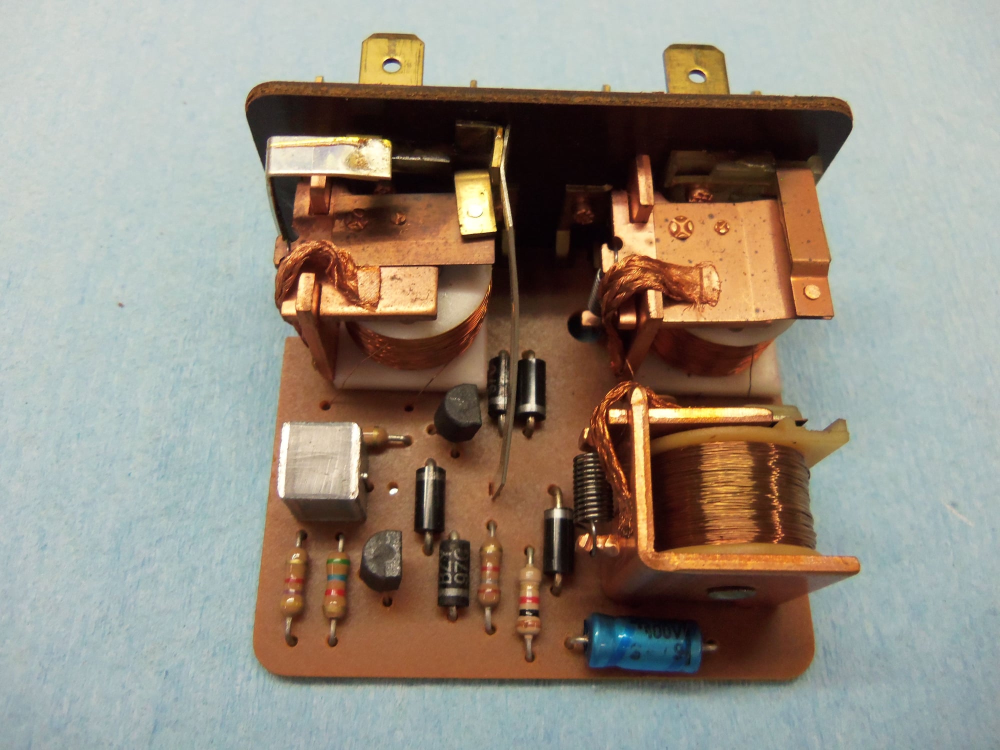
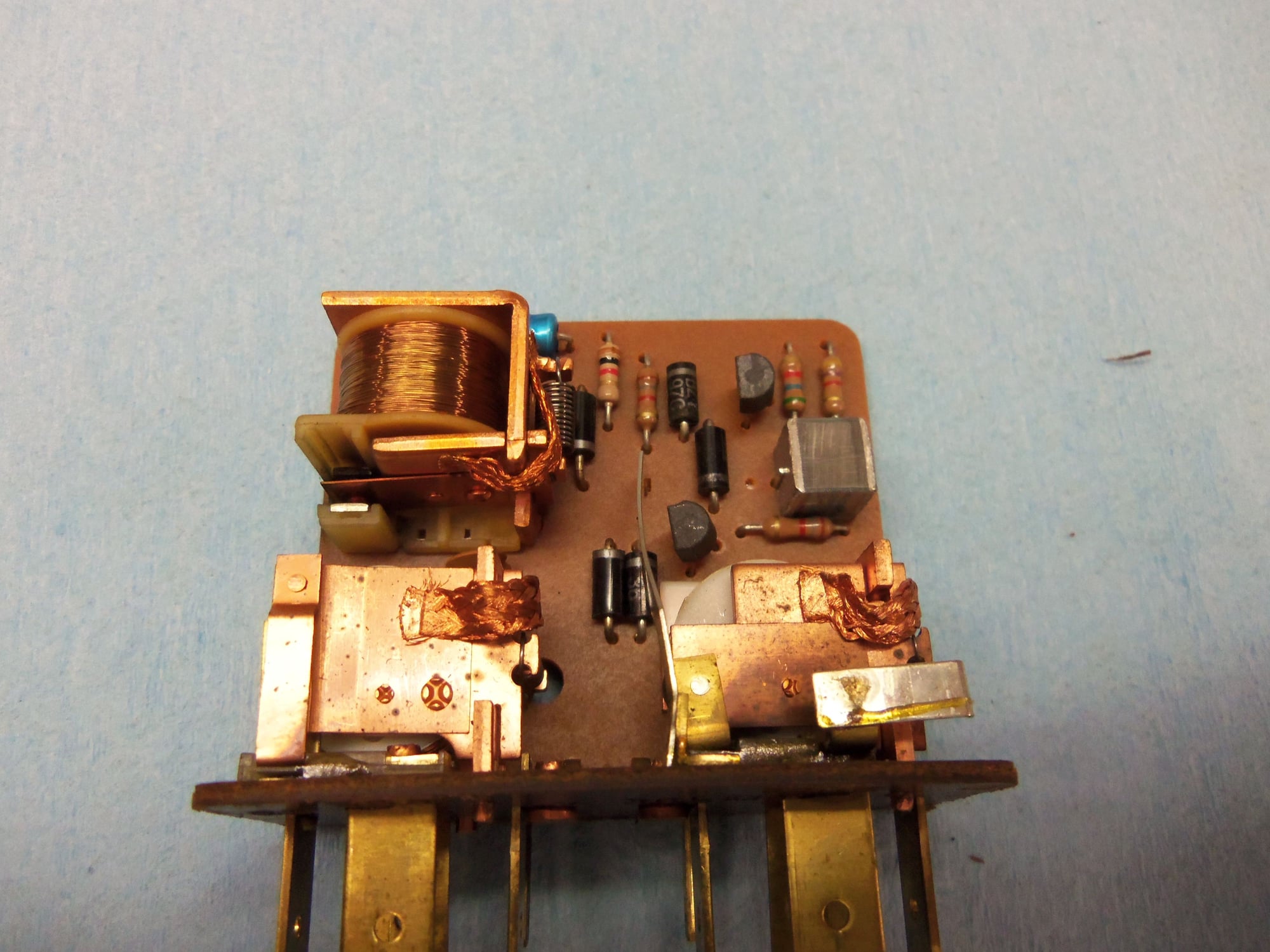
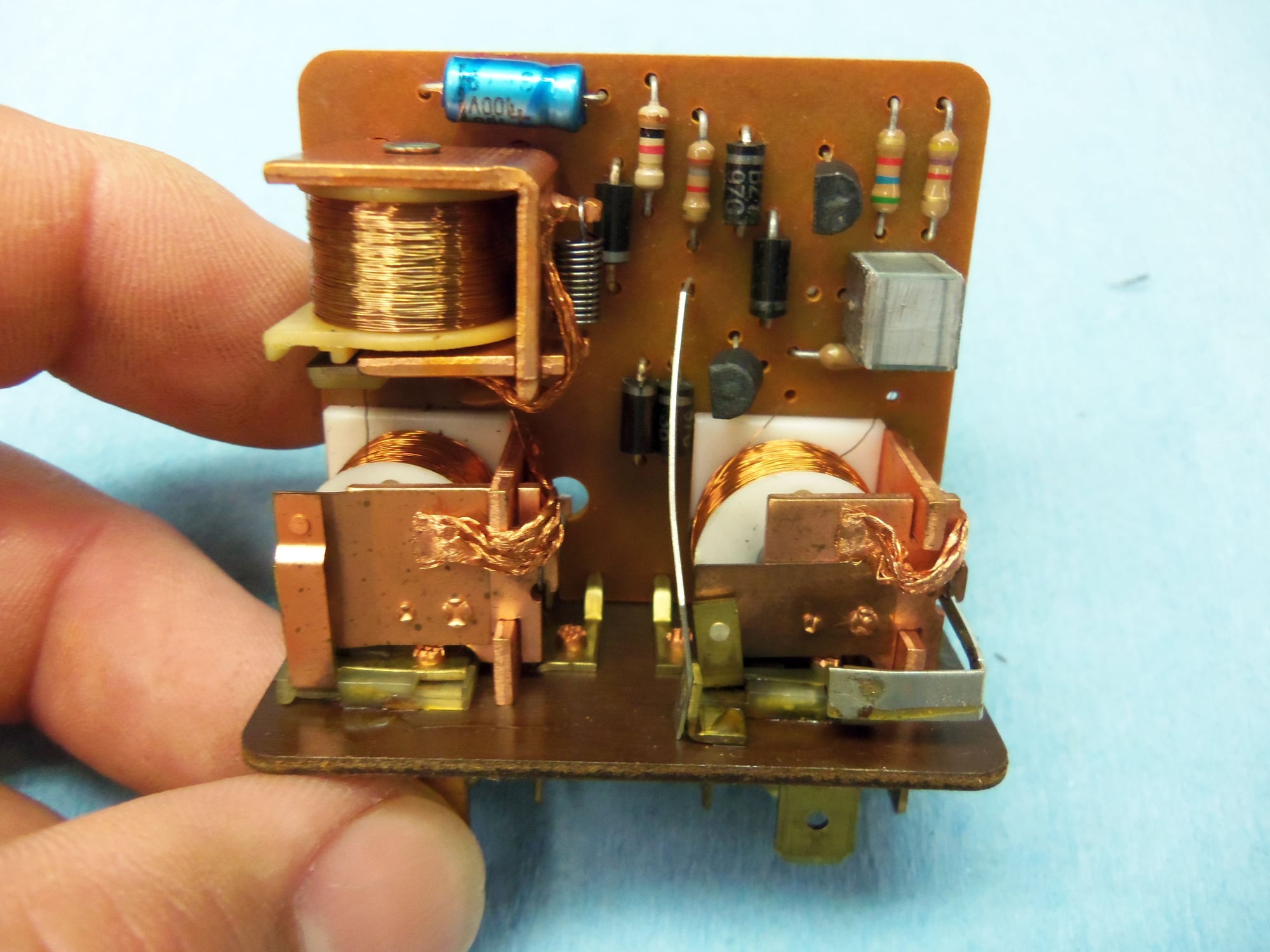
Three relays and supporting components.
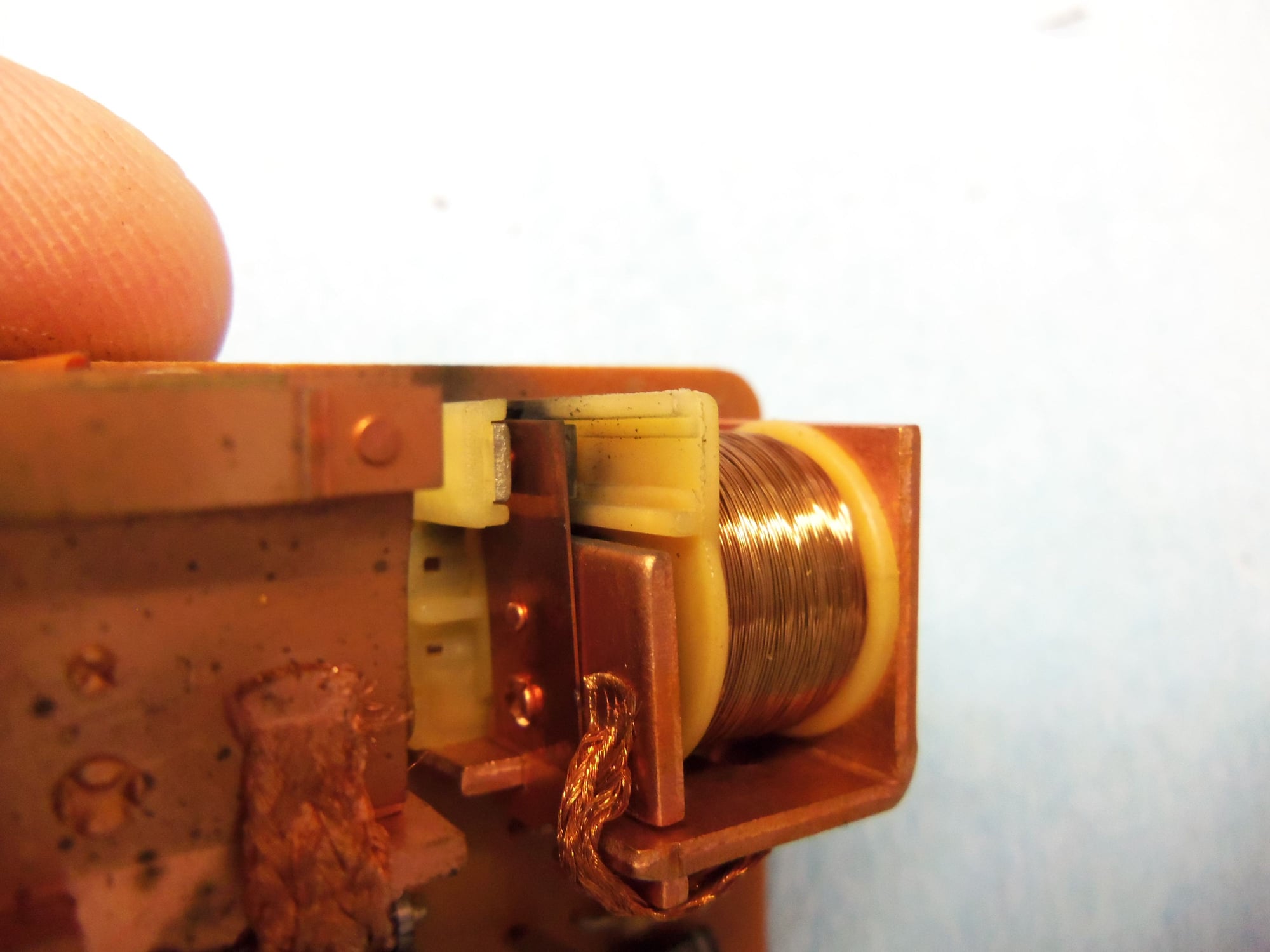
I noticed that this set of contacts looked a little darker than the rest. I suspected that this was the motor contacts. I sprayed it with DeOxit D5, then ran many thin strips of paper through the closed contacts. Alot of carbon came out with the papers.
Contact had dark residue around it.
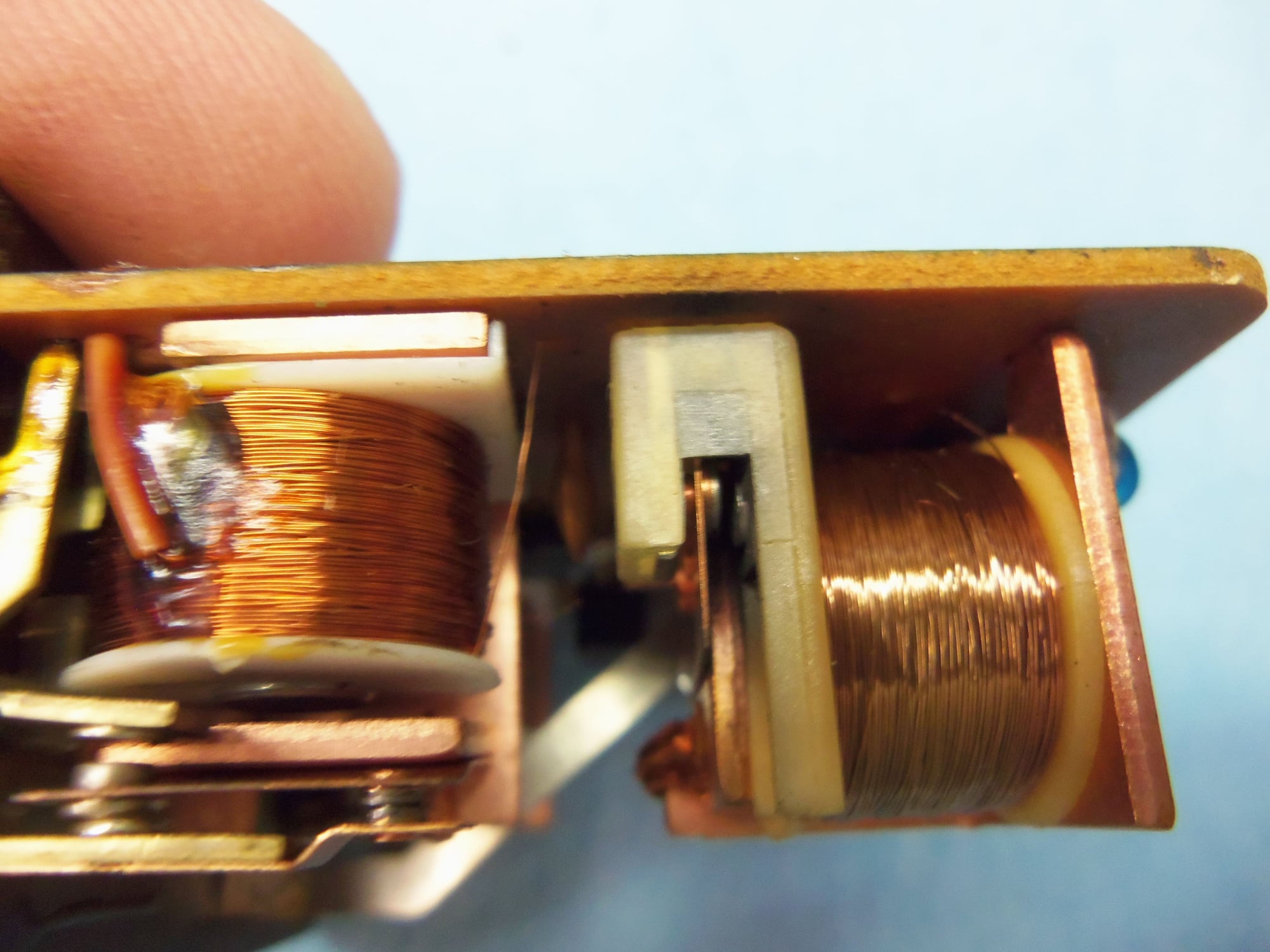
As well, I cleaned both the Normally Open and Normally Closed contacts on the two relays for LOW and HIGH beams for the headlights. A surprising amount of carbon came out on the papers as well.
N.O./N.C. contacts.
N.O./N.C. contacts on other relay.
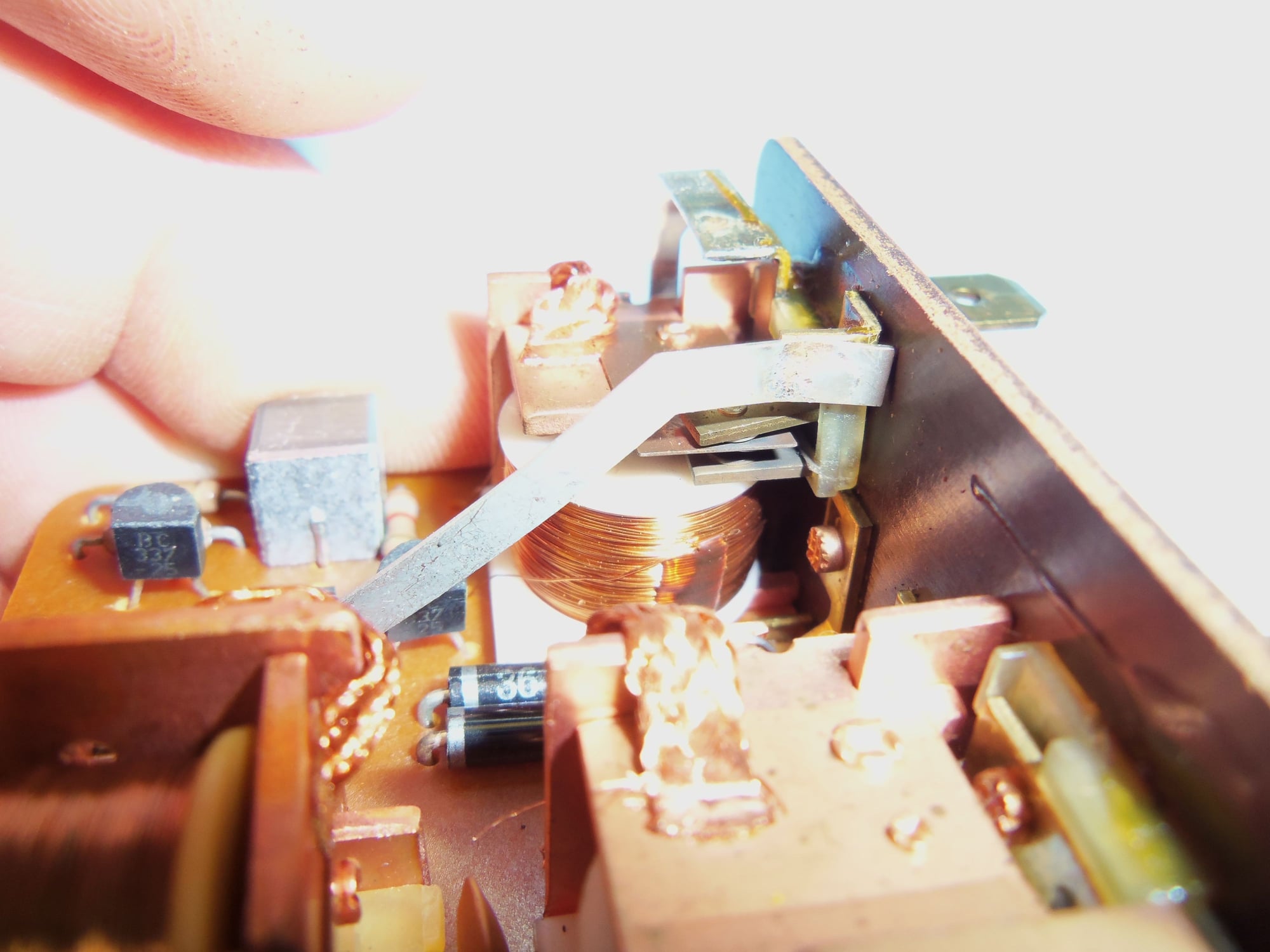
DeOxit D5, used paper strips, relay assembly, and small pick used to open/close the contacts.
I was able to recrimp the aluminum housing around the back of the circuit board using a brass block and a pair of Knipex pliers. I placed the block against the opposite end of the housing. By putting one jaw of the pliers against the block, I could use the other jaw to bend the aluminum lip back over. It is ugly, but it works.
Ugly, but secure.
The relay is back in the CE panel, but testing will have to wait until I put power back on the Red Witch again.
great pics and details thanks for sharing. I hope this works for you
Originally Posted by Socal_Tom
Neat thread, thanks for documenting everything.
Thank you, gentlemen! I appreciate it. In a long ago thread on headlight relays, dr bob asked for good photos for possible reverse engineering of the headlight relay assembly. I sorta thought this might help him.
Plus, this shows there is not much to cleaning the contacts on the headlight relay.
Originally Posted by Imo000
Next time you can use cardboard to clean the relay contacts too.
As a follow up to the previous posts, today, the headlights won't raise.
They half raised the first time I tried, and now don't raise at all. The bulbs illuminate, though.
I think my next step is to R&R the headlight motor for cleaning.
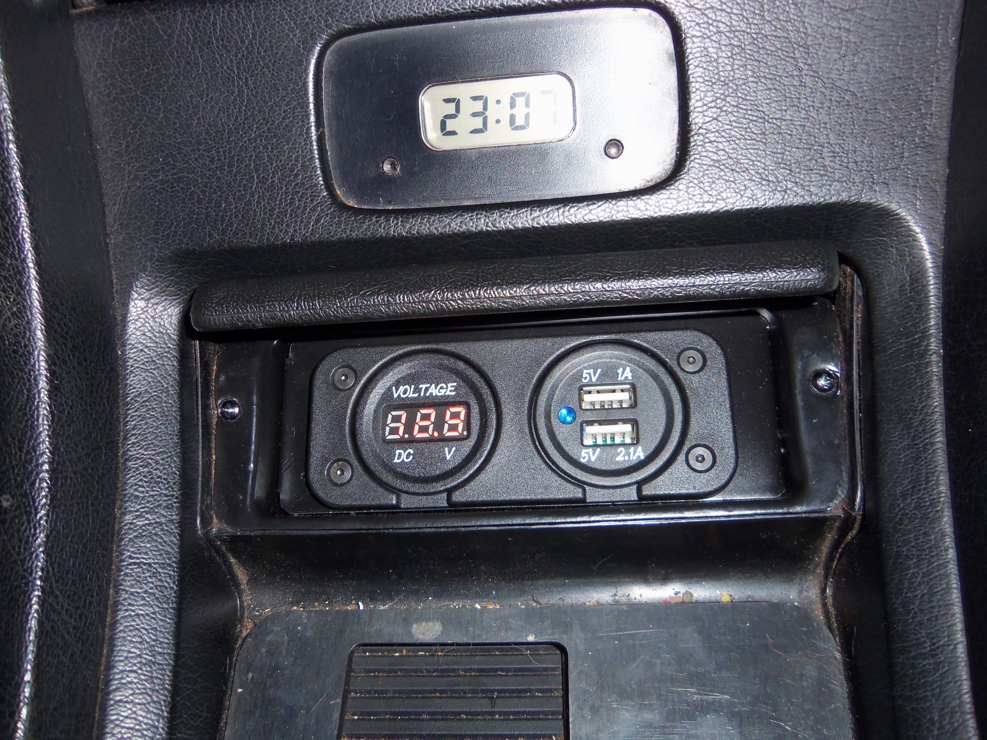
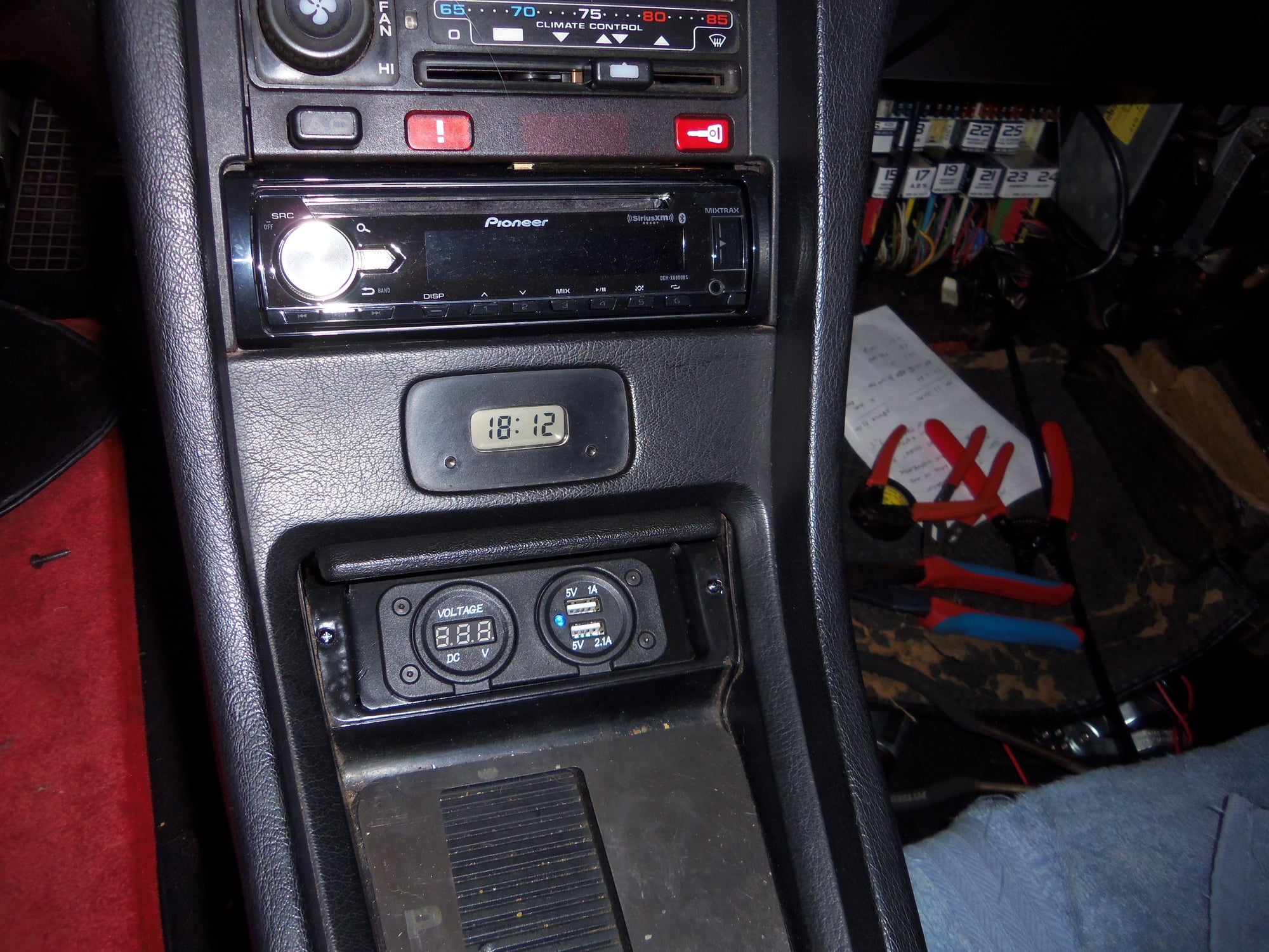
Today, I finally put a little project to bed. I fitted a digital voltmeter and a dual port USB charger in the ash tray area on the Red Witch.
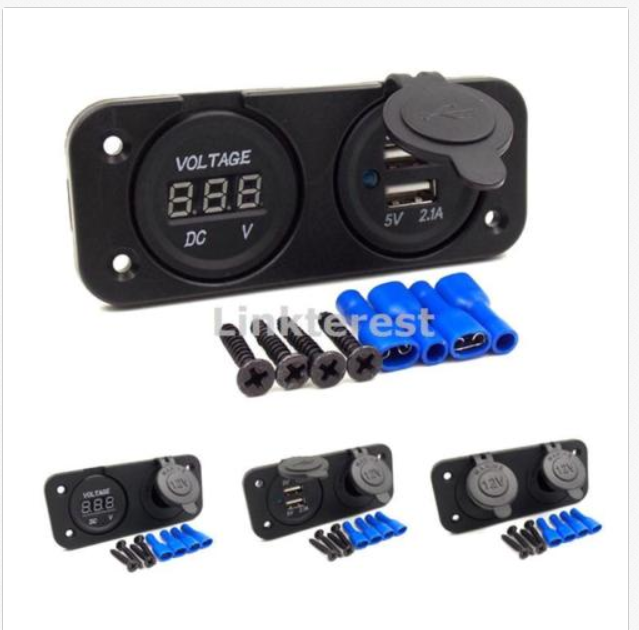
I don't smoke, so I have no use for an ash tray. I had never been able to get adapters to work reliably in the cigar lighter. I had been turning ideas over in my head on how to rig up a charging port in the ash tray. I had looked at ideas from other 928'ers here on Rennlist. Last year, I tripped over this on ebay:
It took me until this past week to finally get started on it.
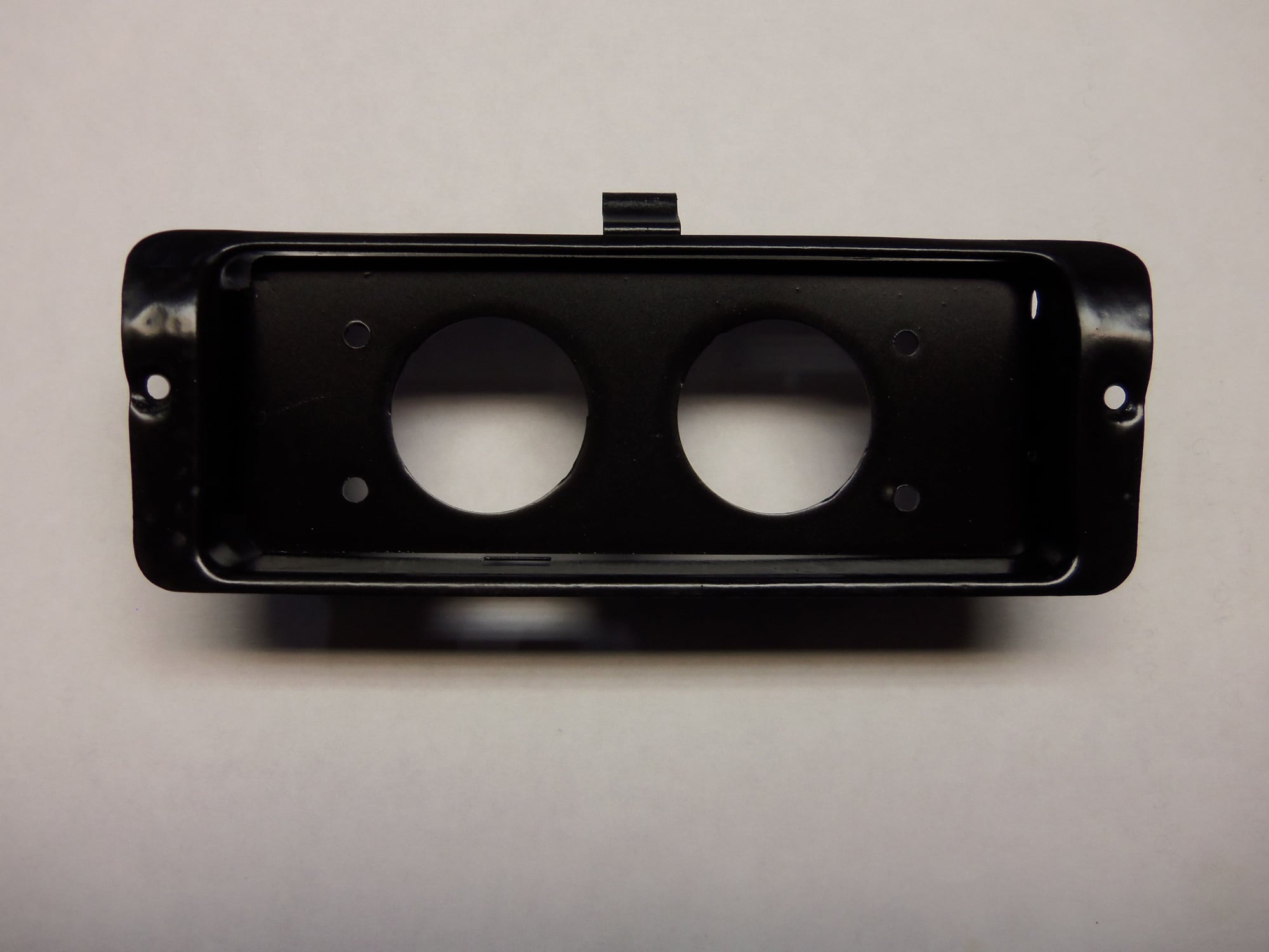
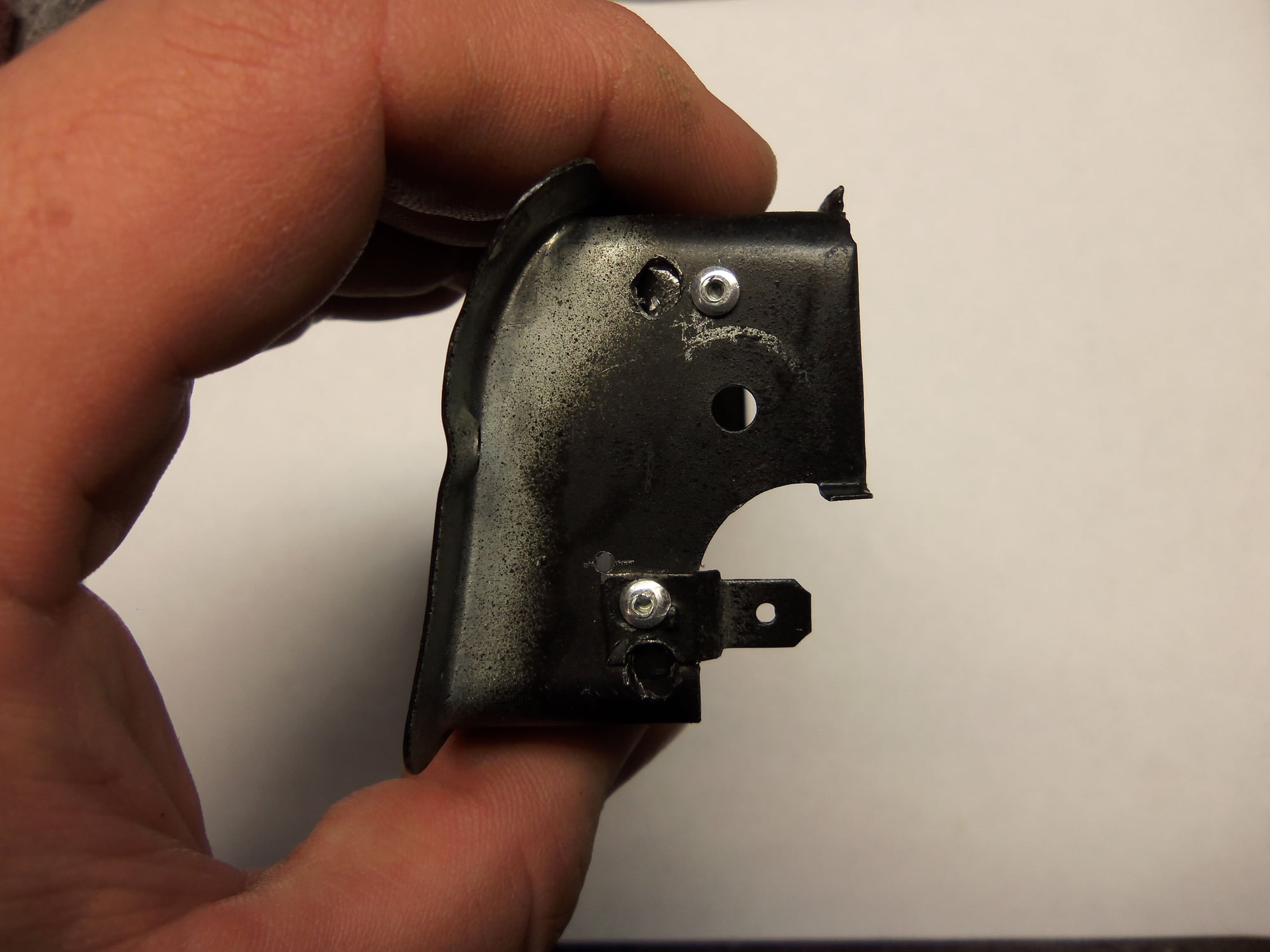
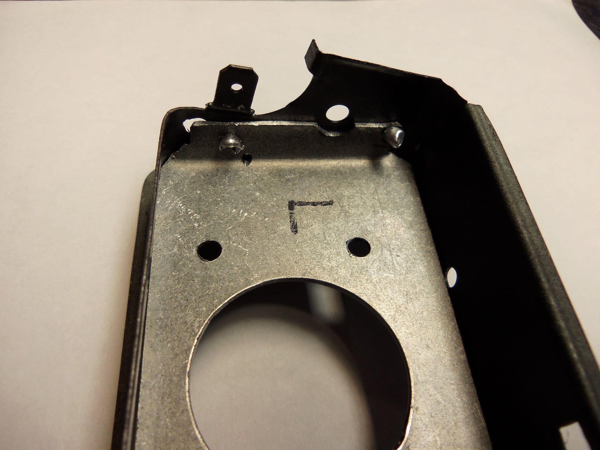
The panel would not fit right into the ash tray housing. The cigar lighter blocked it. I removed the cigar lighter by drilling out the spot welds holding its panel in place. As well, I drilled out the rivets holding the plastic cover to the frame.
I cut and bent a piece of thin sheet metal to fit the opening of the ash tray frame. I secured it with pop rivets to the sides of the frame. Rather than cut out a large opening in the sheet metal panel, I used a 30mm knock out punch to put two holes in it. That way, the voltmeter and USB charger went through the plastic trim panel and the sheet metal panel. Stronger that way. As for fitment, I biased the voltmeter and USB chargers as far down in the frame as they would go. I figured the opened lid would obscure part of the area. I was right.
A coat of satin black paint, and the frame was done.
No photos of the fabrication process, as it was ugly...
EDIT: GO TO POST #80 FOR PHOTOS OF THE FAB PROCESS.
Doesn't look too bad, though there are cosmetic flaws.
Low heads of the rivets did not have clearance issues.
3/32" rivets secure the sheet metal panel to the frame.
Back side showing some of my alignment notes.
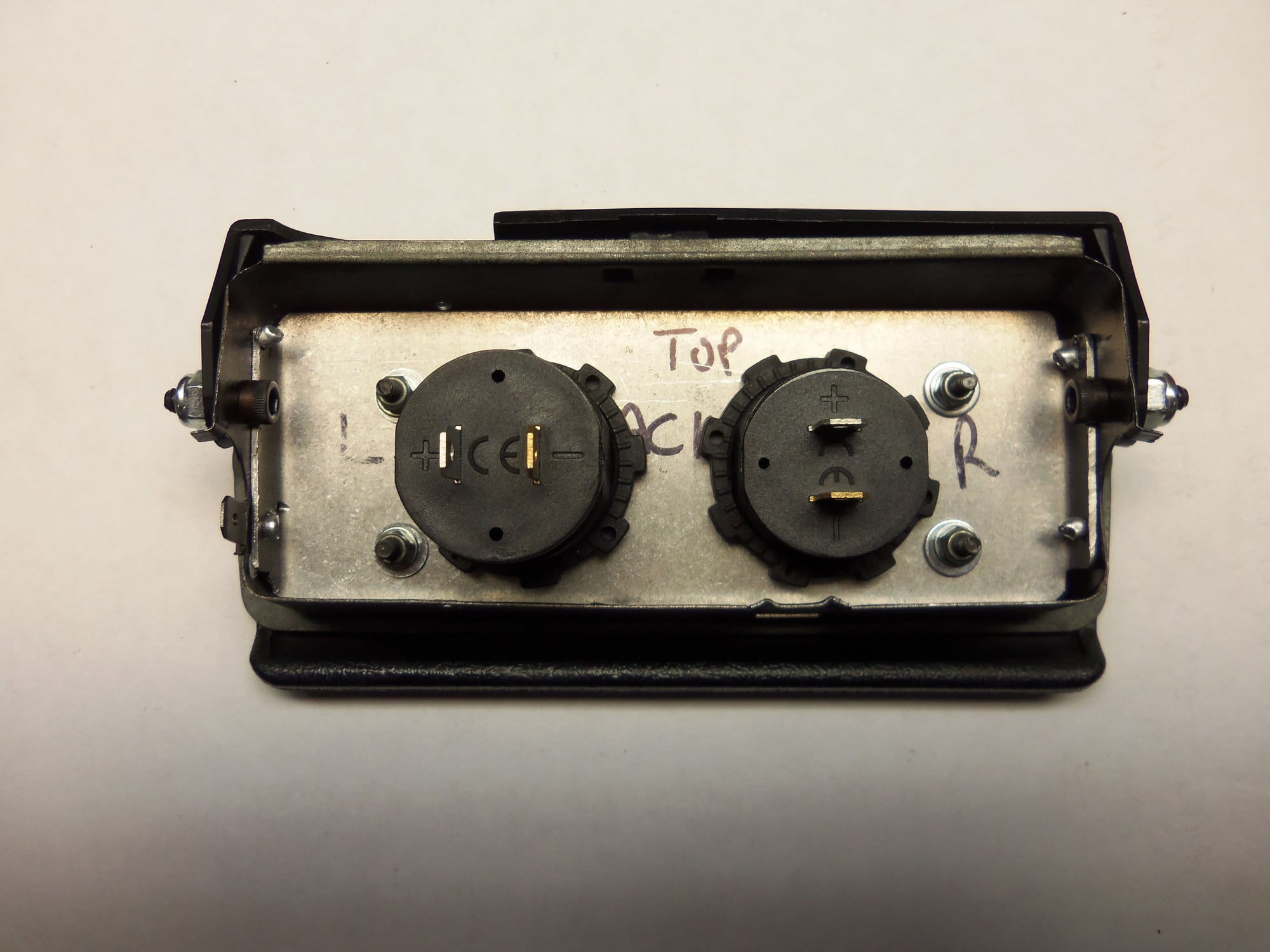
I used M3 counter sunk socket head screws with washers and nylon lock nuts to secure the plastic panel to the sheet metal panel. Then installed the voltmeter and USB charger with the installed spanner nuts. I made sure the nuts were quite tight.
I used 8-32 socket head screws and nylon lock nuts to attach the lid back to the frame. I put the heads of the screws inboard for clearance to the bodies of the voltmeter and USB chargers. The nylon lock nuts and threads of the screws stuck out the sides of the lid far more than the original rivets did. I was concerned this would cause clearance issues mounting the unit back in the console. It did not.
Completed backside, showing various fasteners and nylon lock nuts.
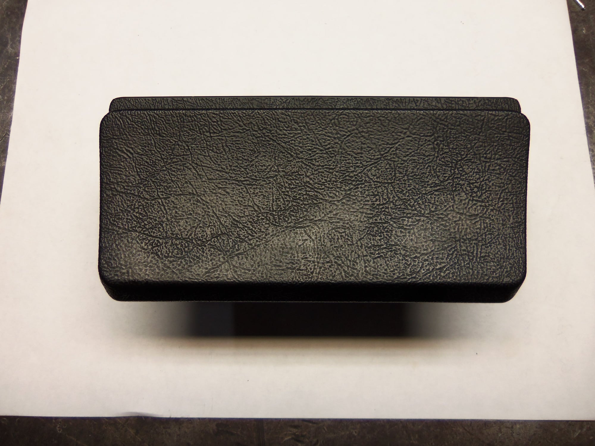
Lid closed.
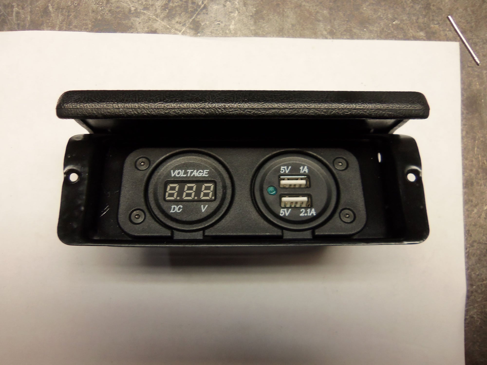
Lid open.
Bench test of the voltmeter and USB chargers.
Because of the nuts and threads sticking out of the sides of the lid, I was not able to just drop the ash tray assembly back into the console. However, before I got happy with the Dremel, I tried coming in from the backside of the console. It was tight, but it worked! I had to roll the frame forward as I moved it in place so the lip would go over the mounting flange. The test fit looked good. Only issue was the male spade terminals at the back of the USB chargers were tight against the insulation on the floor pan. Of course the ash tray mounting flange screw holes were stripped out. I used blackened 4-40 screws with nuts on the bottoms. It took some finger dexterity to get the nuts started, but it worked.
I dealt with the tight wiring terminals by trimming the male spades down, and trimming the female spades down as well. Once the female spades were crimped on the wiring, I insulated everything with heat shrink tubing. The wiring is tight against the floor pan insulation, but I don't think it will be an issue.
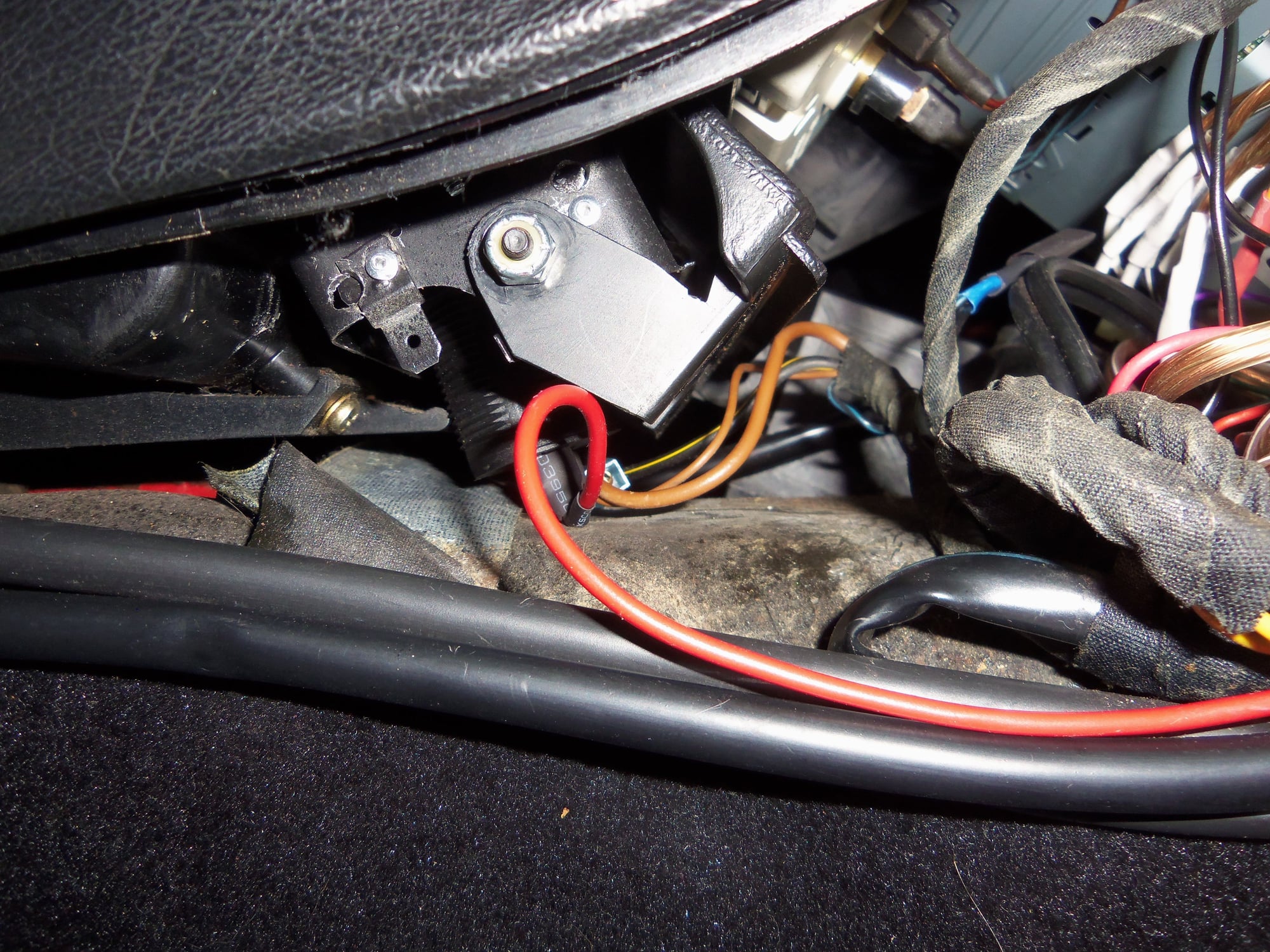
On the subject of wiring, I used alot of what was already there. For the ground, I just made a Y cable that tied the grounds of the voltmeter and the USB chargers to a single male spade. That male spade got inserted into the female spade on the factory ground wire that originally connected to the ashtray frame. To power the voltmeter, I used the existing power wire for the cigar lighter. It is powered by the accessory X-bus, so it only comes on with the key in 'ACC' or 'RUN'. As for the USB charger, I ran a wire to the CE panel, and tied into unused fuse slot 22. This slot is powered by battery bus 30, so it is hot all the time. I used a spade fuse tap adapter to wire it in. For an attempt at neatness, I ran the wire down behind the CE panel then back up the front to meet up with the fuse adapter. In the future, if I pull the CE panel again, I will attach the wire to the load side of fuse slot 22 for a much neater installation.
USB chargers adapter wiring is tight against the floor pan insulation, but workable.
Fuse tap adapter.
Fuse tap adapter in slot 22, with wiring run down for an attempt at neatness.
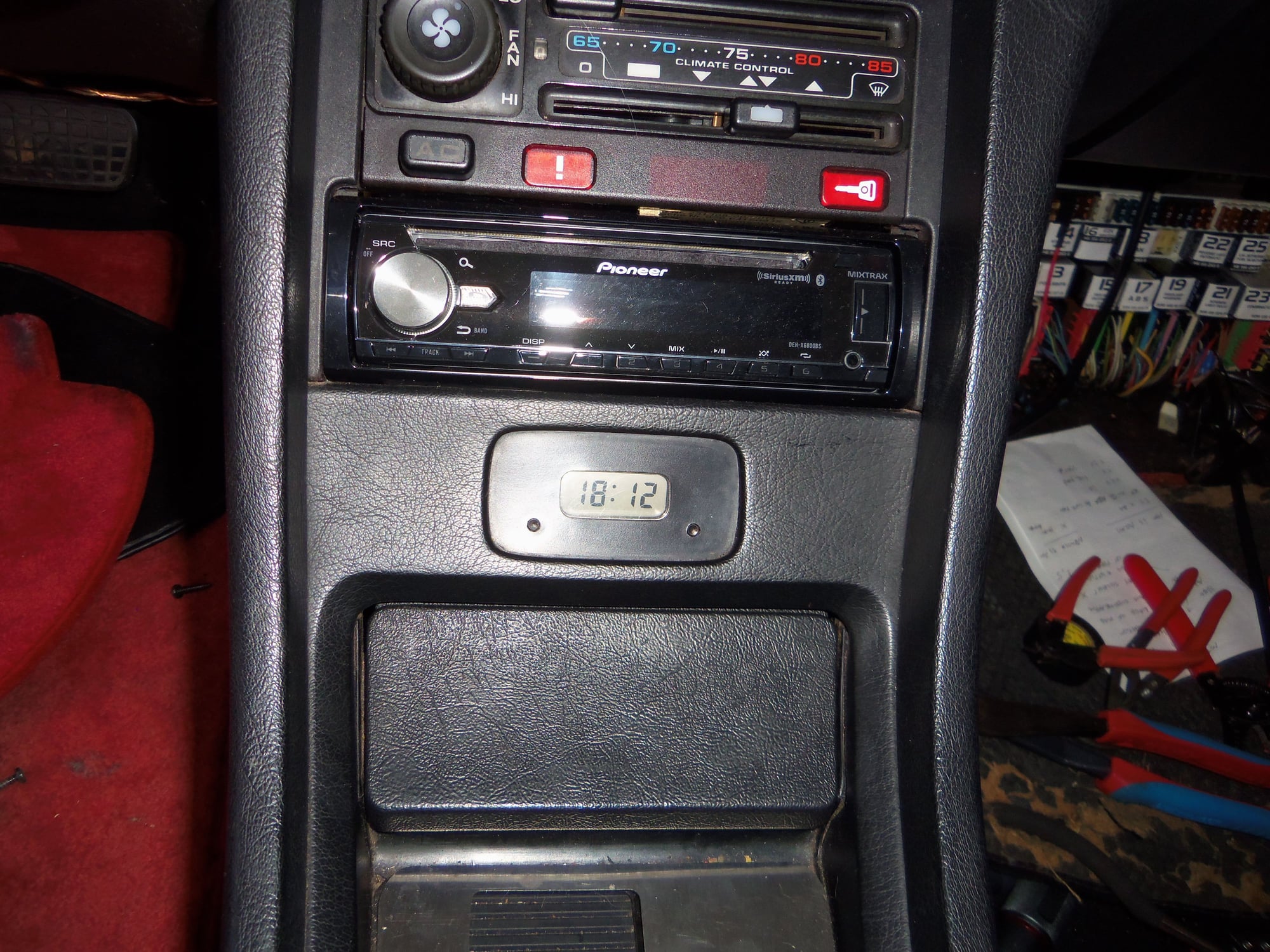
Like nothing happened...
There it is!
Tough to see due to the flash, but the voltmeter is powered up.
Lousy shot with the flash off. Voltmeter reads 13.5.
That is sweet. I was hoping to take the easy way out and find a USB that would plug into the cigar lighter thing but like you, I haven't found anything that will fit. I might have to go this route.
Looks great Seth!! I'm going to make a spacer to bring mine up flush with the top of the ashtray. Either not going to close it, or I might remove the whole thing and fab a new closeout panel. We'll see. Keep up the great work and documentation.
As a follow up to the previous posts, today, the headlights won't raise.
They half raised the first time I tried, and now don't raise at all. The bulbs illuminate, though.
I think my next step is to R&R the headlight motor for cleaning.
That is sweet. I was hoping to take the easy way out and find a USB that would plug into the cigar lighter thing but like you, I haven't found anything that will fit. I might have to go this route.
Originally Posted by Chris Lockhart
Looks great Seth!! I'm going to make a spacer to bring mine up flush with the top of the ashtray. Either not going to close it, or I might remove the whole thing and fab a new closeout panel. We'll see. Keep up the great work and documentation.
Since the European cigarette lighters are shallower (it is on my Passat too) so their plug-in USB ports must be shallower too so getting one from Europe might work on the 928, but this is just my theory.

 11-09-2016, 01:00 AM