When you click on links to various merchants on this site and make a purchase, this can result in this site earning a commission. Affiliate programs and affiliations include, but are not limited to, the eBay Partner Network.
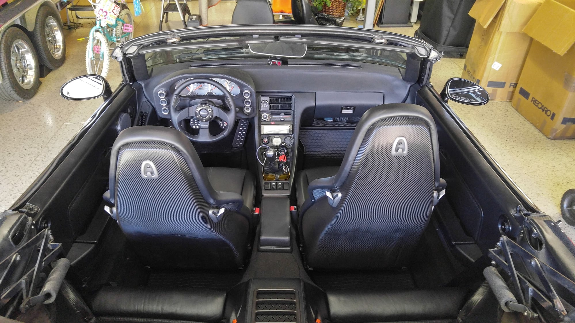
The big differences are the firmer base cushion, the slightly higher headrest, and the most important - the shoulder support "wings". Did a 1 hour trip in them today and they sit great !
Originally Posted by Carl Fausett
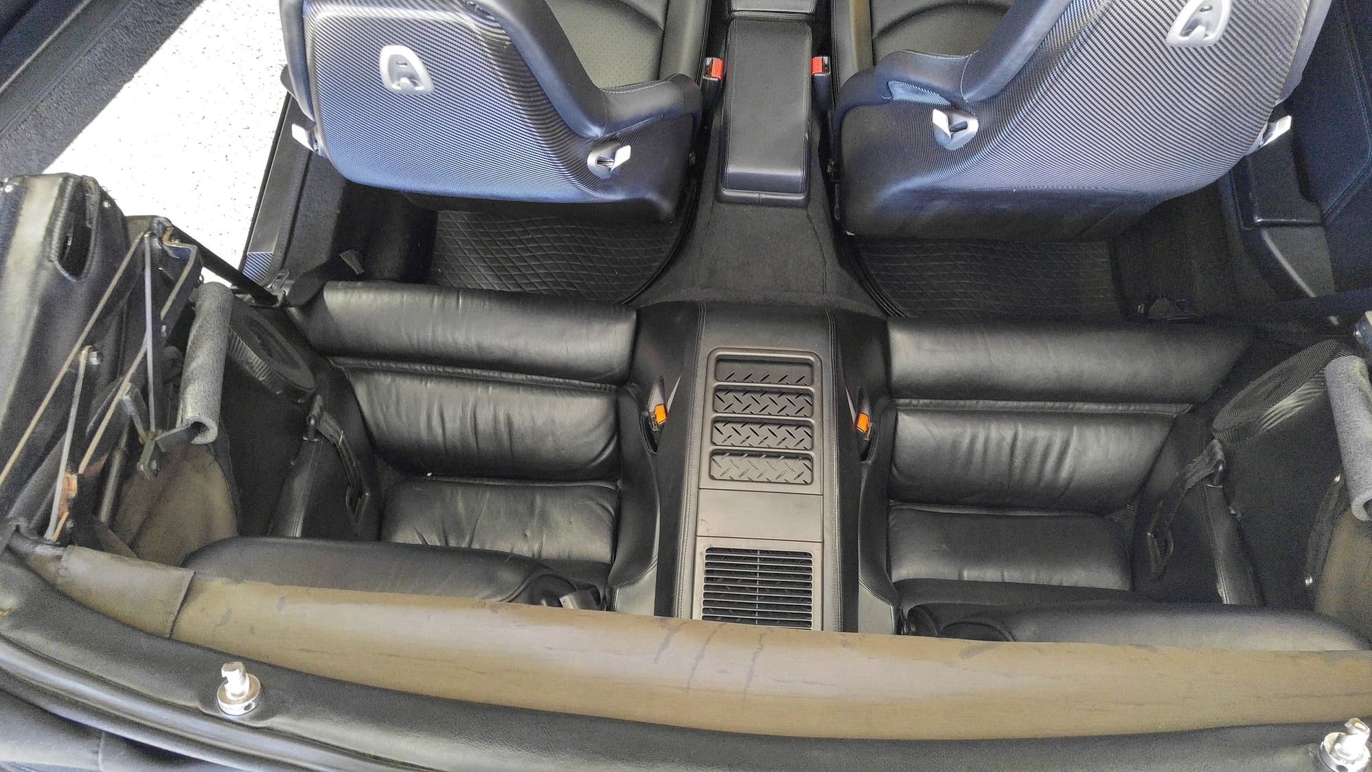
Those seats really are similar in shape to the originals! Very nice. Love the CF-look back plates for your son's feet!
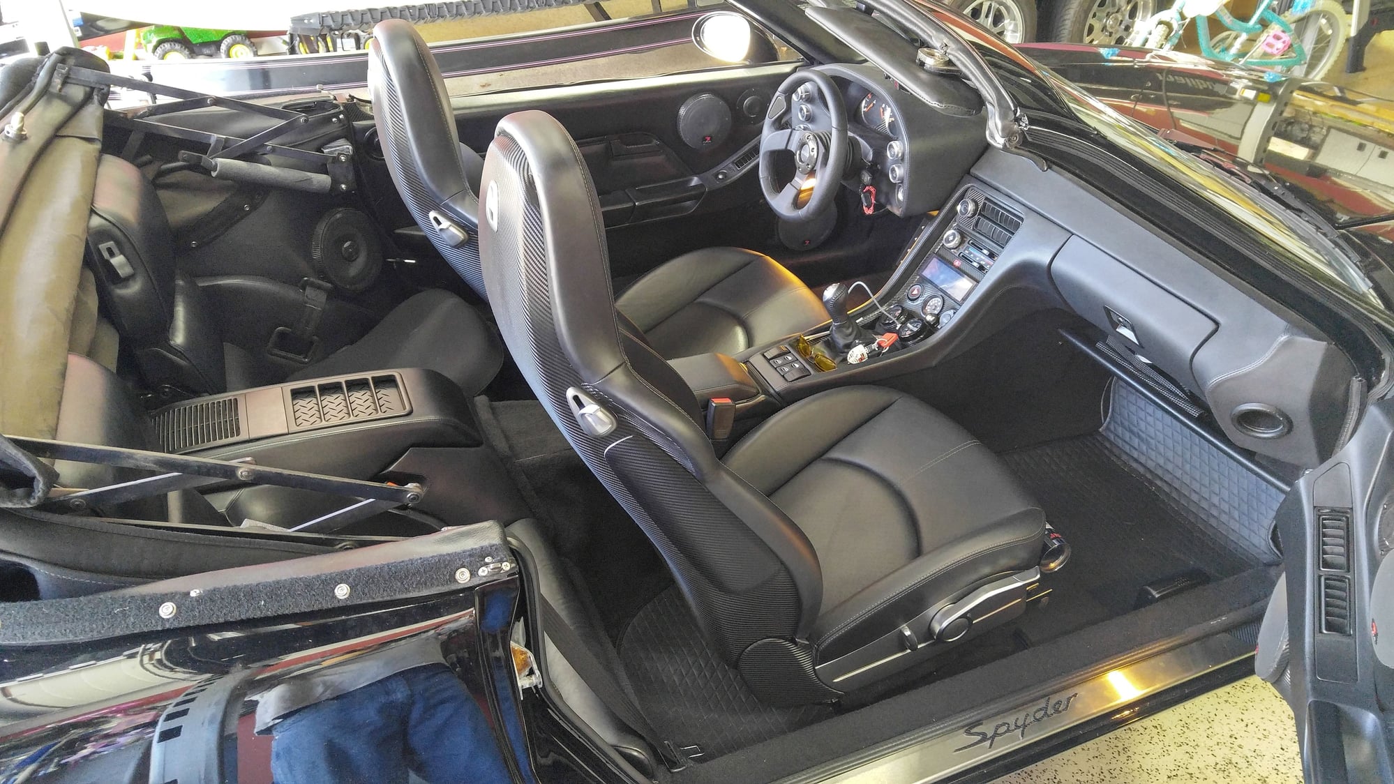
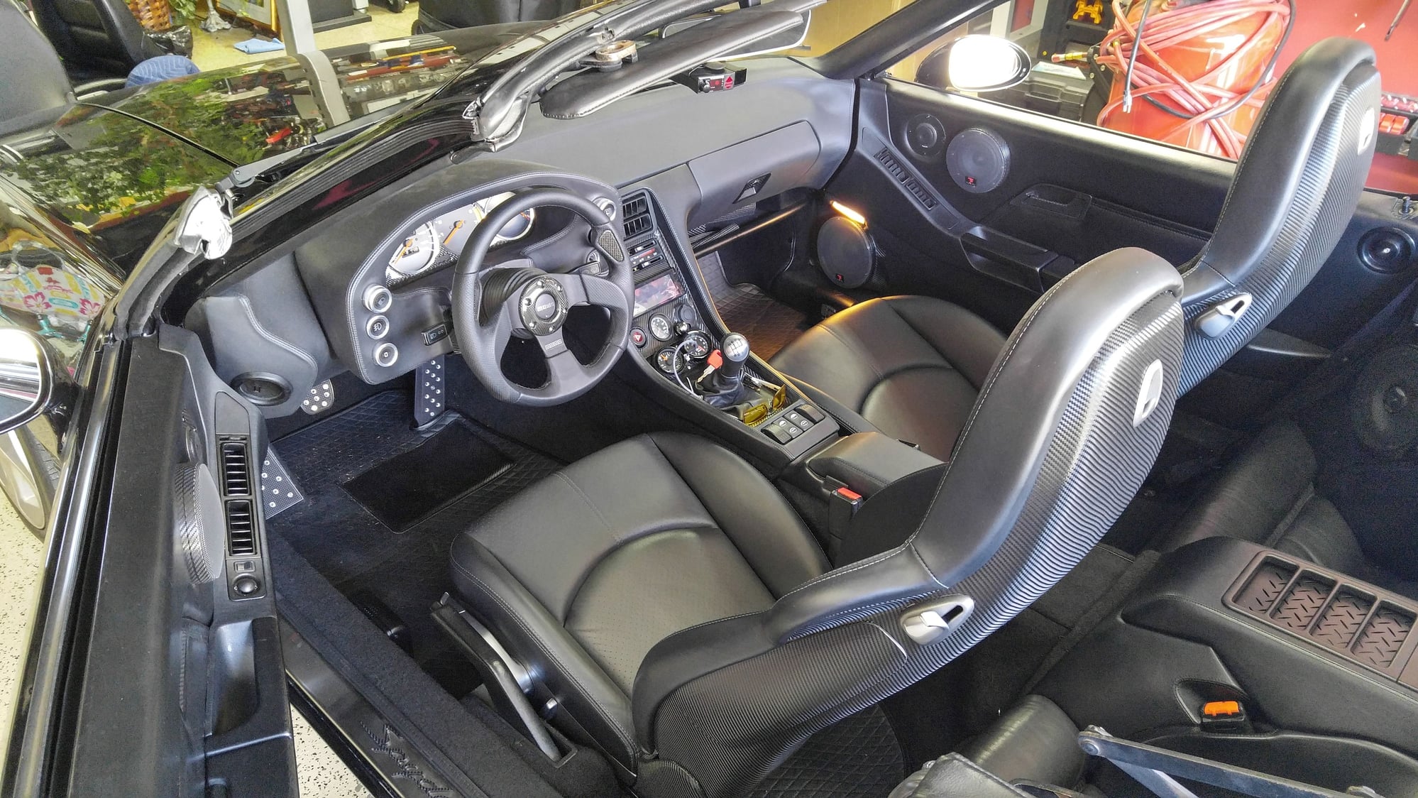
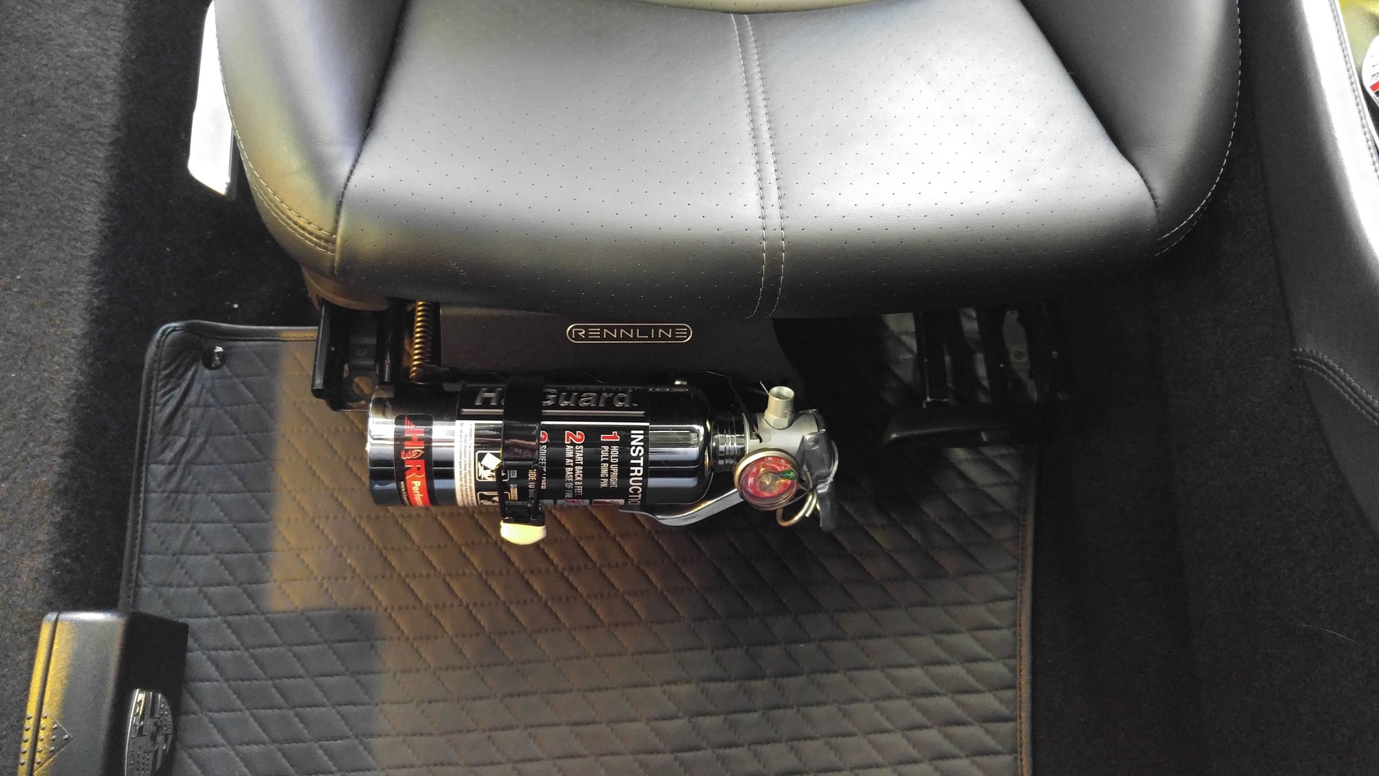
I figured out a way to mount the Rennline 997 Fire Extinguisher Drivers seat mount for power adaptive seats on the passenger side and got the other seat installed today. I could go with the larger fire extinguisher if I moved the cup holder on that side but this has proven to be the best place for one, so leaving it as is for now. Here are some pics.
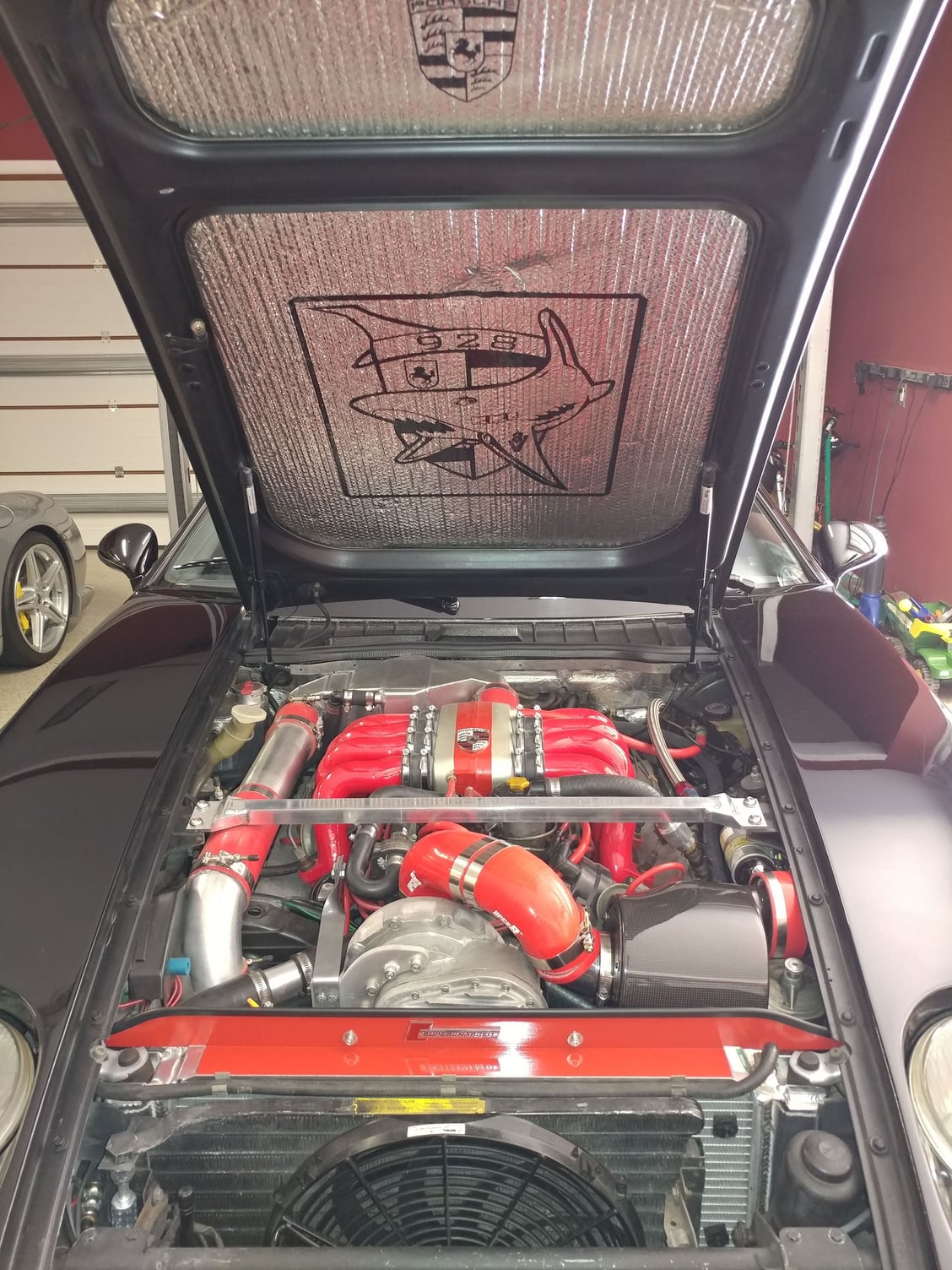
Finally got around to installing the dressed-up spider intake I've had ready for about a year, which is one of the last build projects I had in mind for the car. Had to get it on before SITM
Thanks Mark, and thanks for your input in my thread on the US vs Euro intake legs. I might not have proceeded with the installation of those without your saying they should work fine.
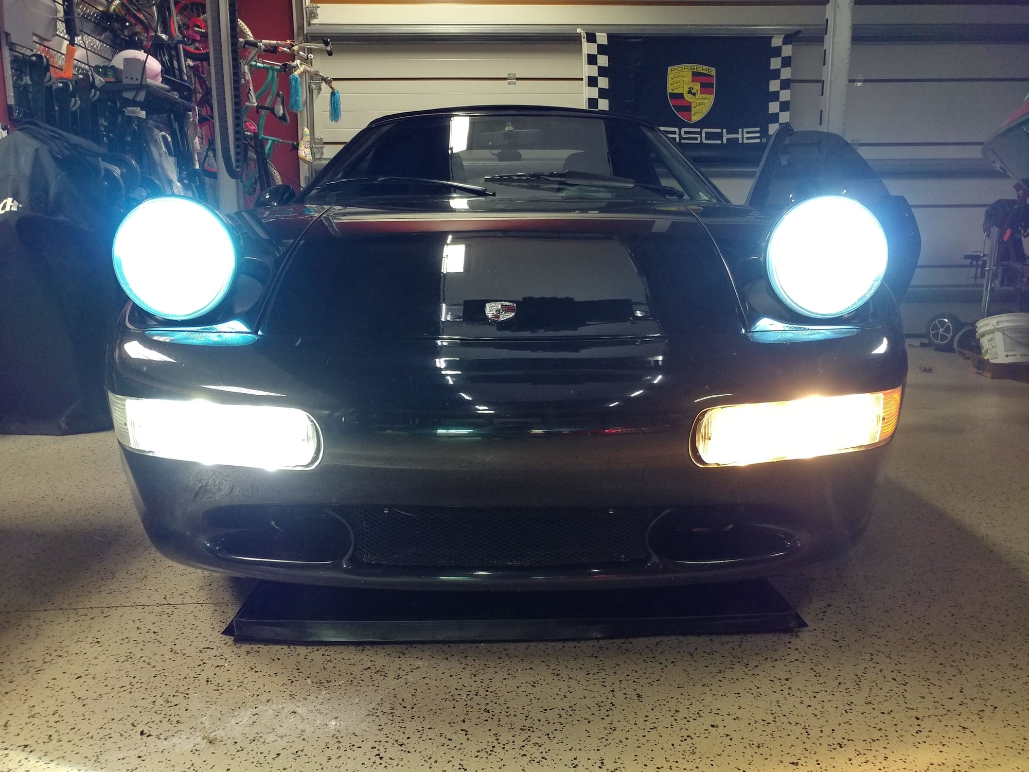
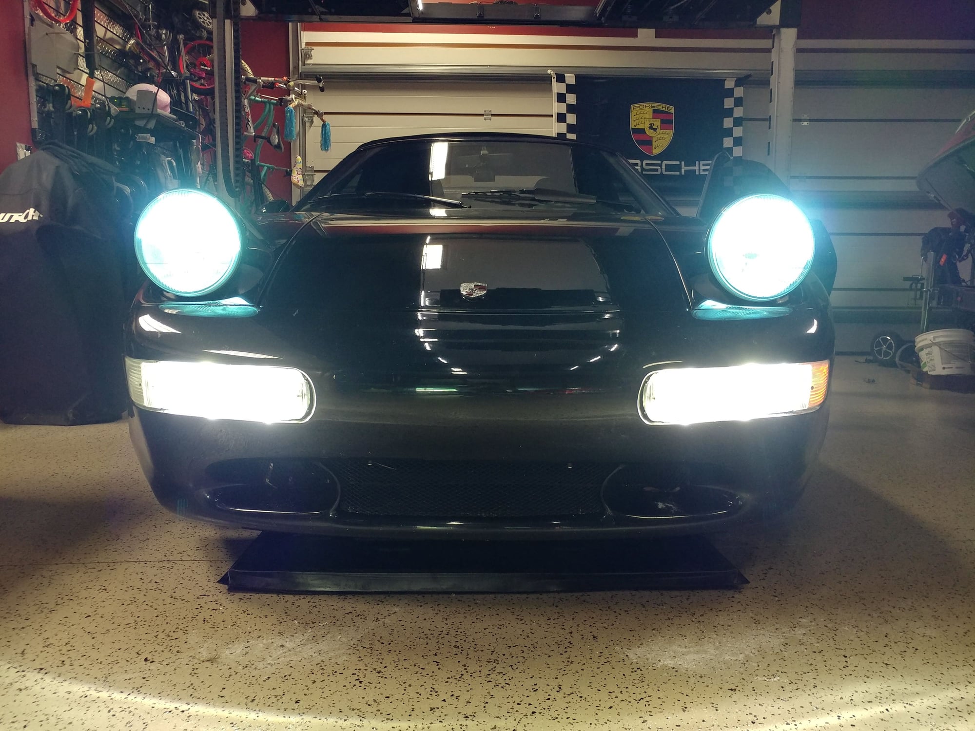
Ever since installing my HID headlights, it has bugged me that the driving lights and fog lights didn't match in color (too yellow), so I ordered some LED H3 bulbs for them and did the install tonight. Now all the front lights match and they're brighter too, even brighter than the KC Hi-Lites 100 watt bulbs I had been running as my driving lights for dark empty roads.
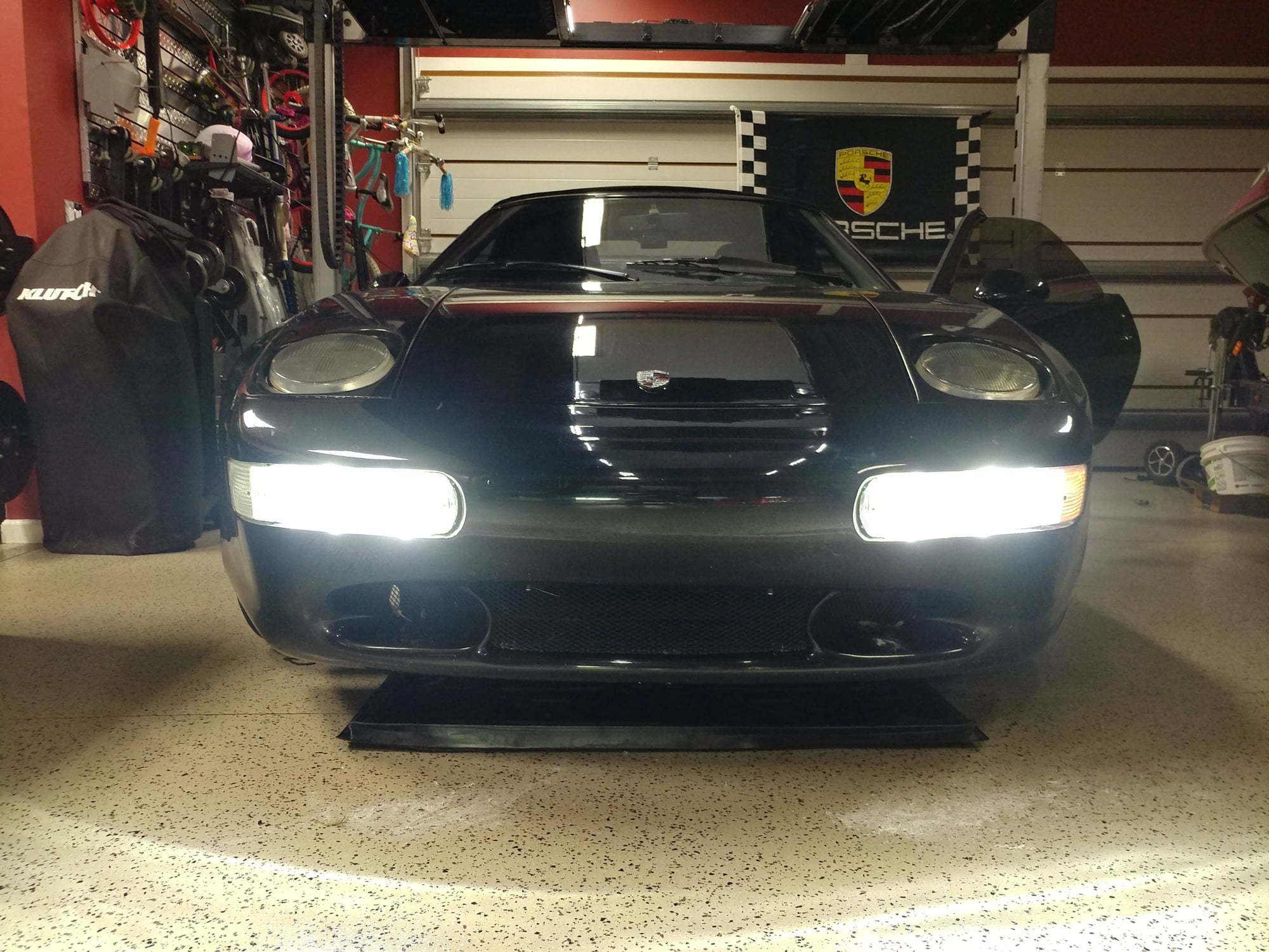
Here are a couple pics after having changed only the Passenger side to the LED with the regular bulbs still in the Driver's side.
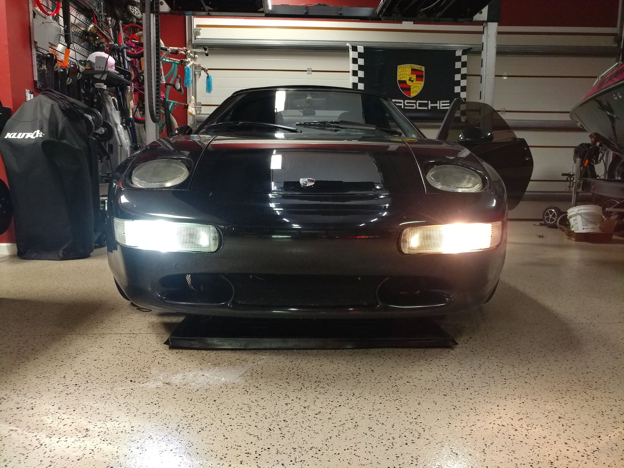
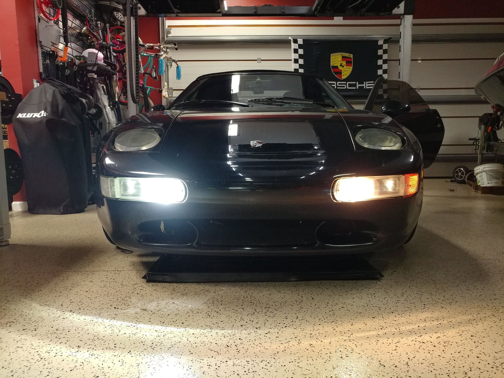
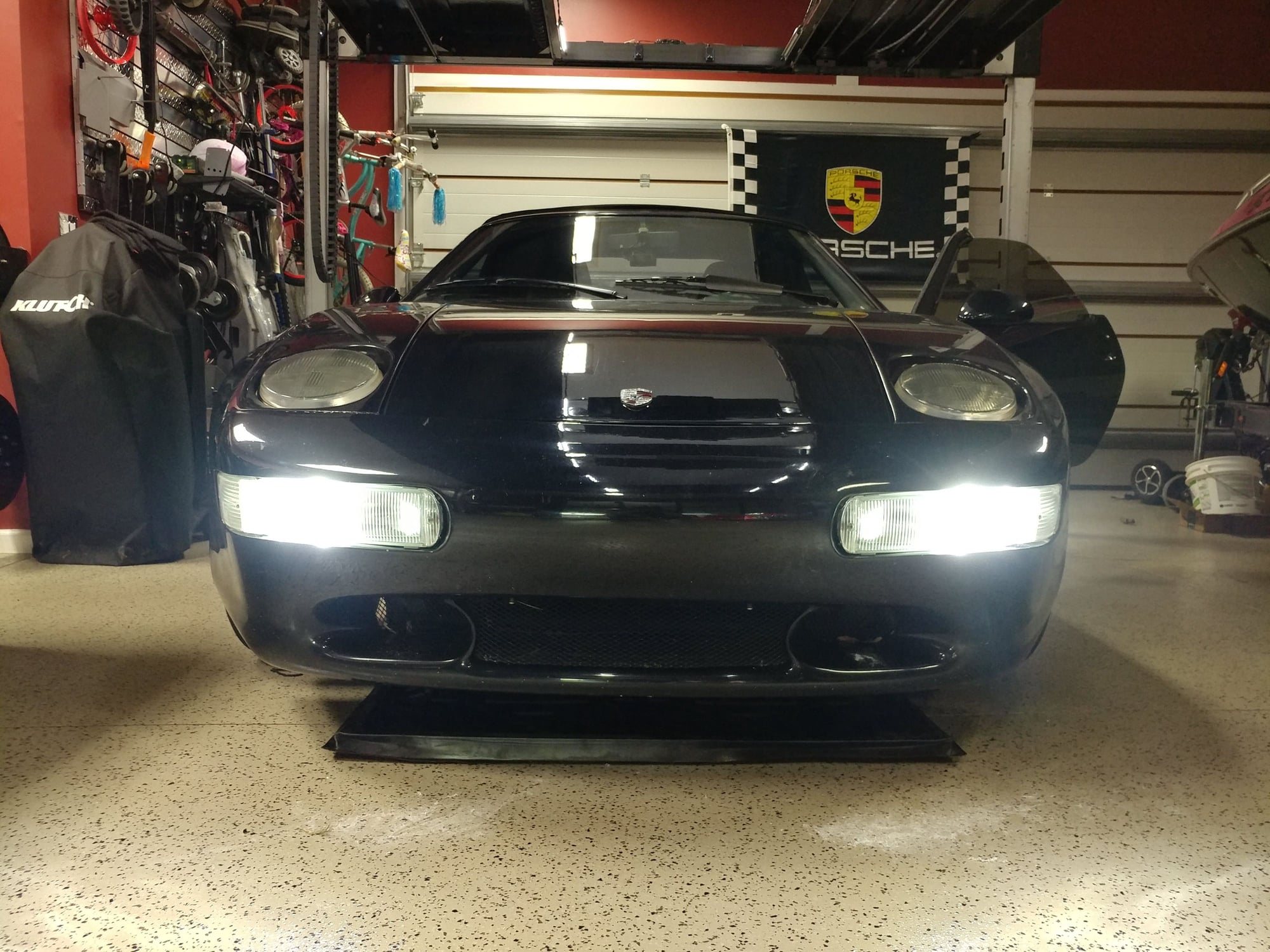
...and here's the completed job. Now everything up front matches and the light output is better too.
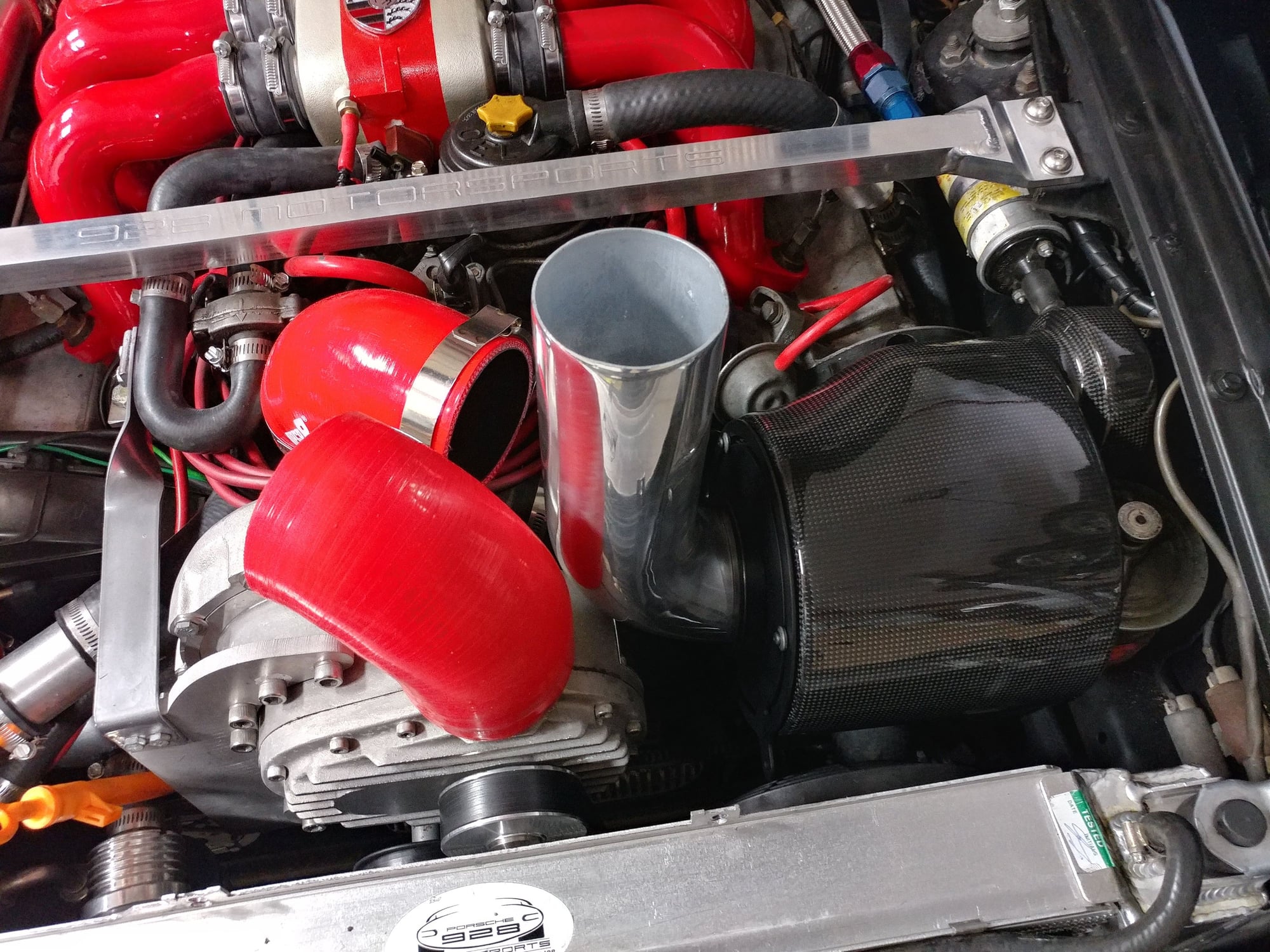
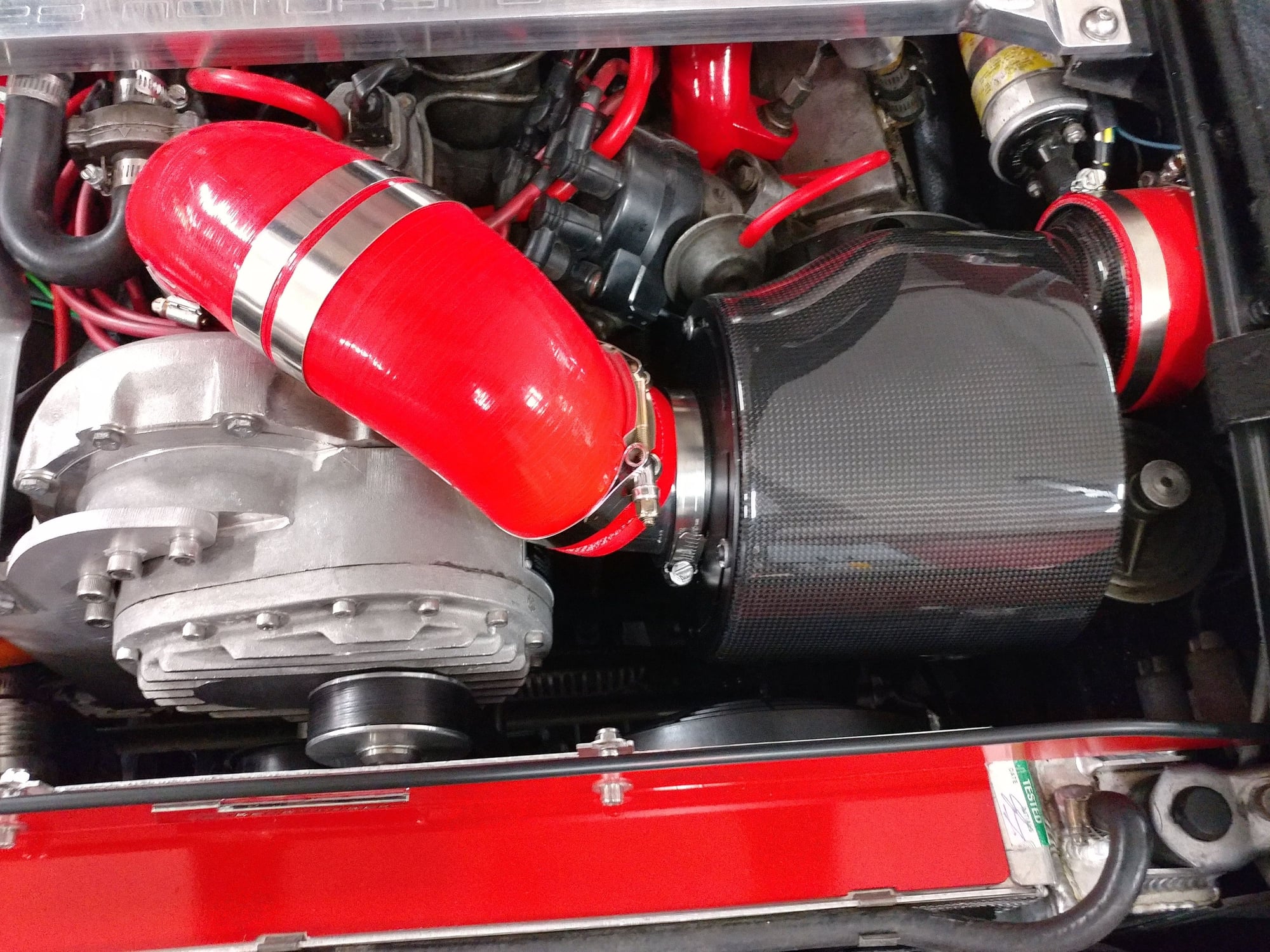
Just completed a true Cold Air Intake on the Spyder.
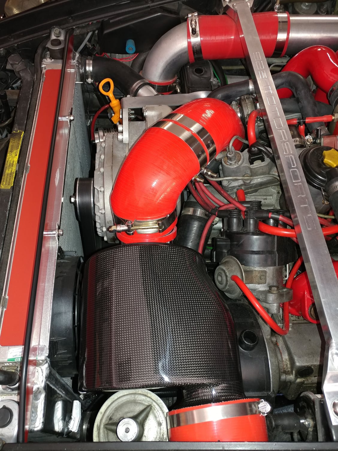
I've completed v3 of the cold air intake on my Spyder and was able to shoehorn it in as originally conceptualized. The airbox itself is a Carbonio TS model that's construction of Carbon Fiber - it's actually very well made and quite pretty.
I loosened the clamp on the ignition coil and slid it forward in the mounting bracket a little bit to add some clearance.
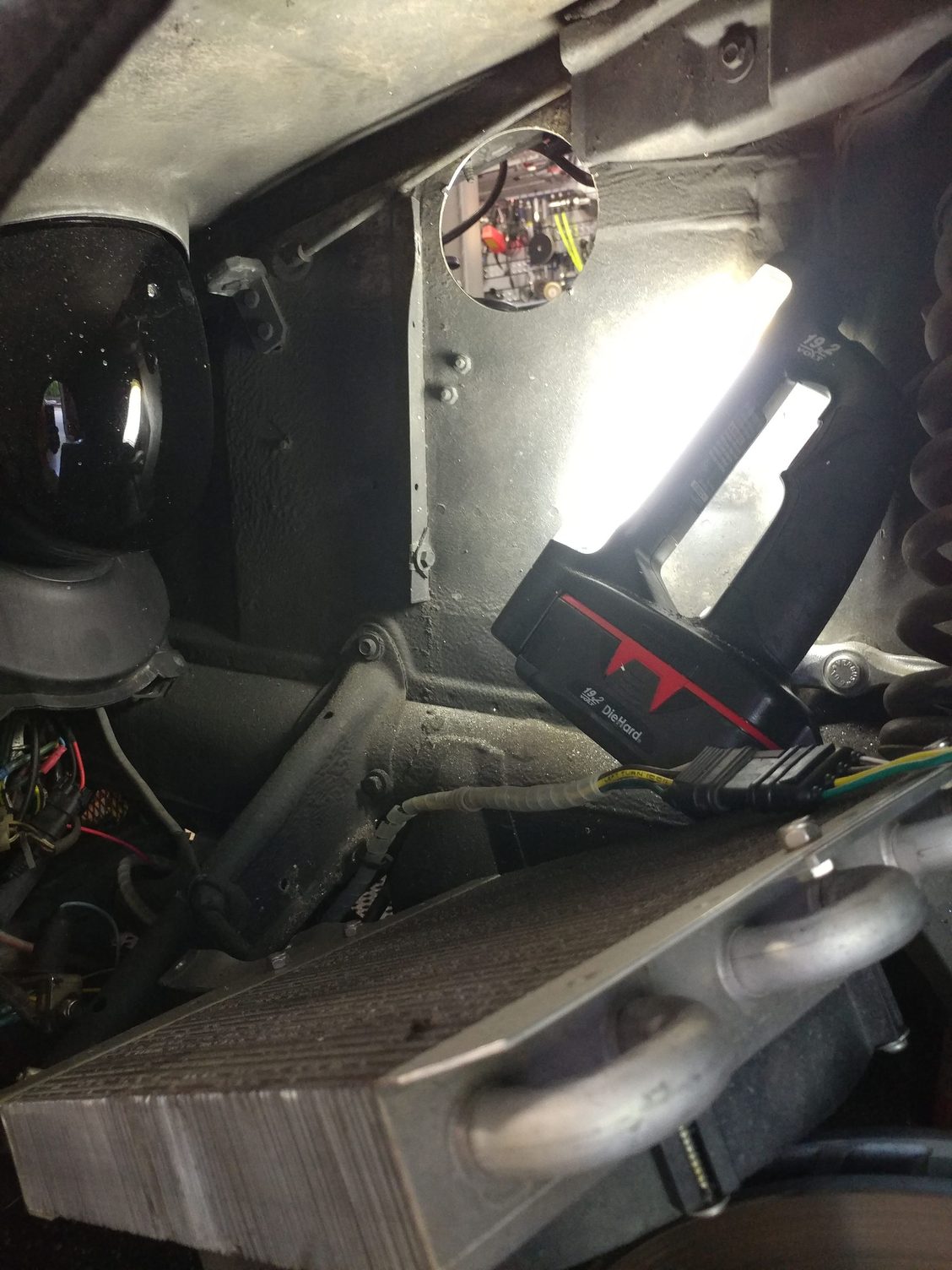
I also had to relocate some wires I had run through the fender for lighting and accessories in the same area where the 4" intake hole would be located.
), trimming most of the flange off the one that was going to protrude through the wheelwell. I used 2 of them so that between the 2 flat sides I could sandwich in a layer of moisture barrier material. I bought a sheet of Frogzskin material that as a circle with 4" center section and a border outside of that, but my initial test of if where I peeled back the adhesive carrier and tried to blow through it showed it to be too restrictive, so I cut up the hydrophobic K&N prefilter I had around the K&N filter on my v1 intake and used that instead. Not sure how much it will do, but might shed some water and help to keep the primary filter in the airbox cleaner - we'll see
I then started fitting things together and mocking up how it would all go. I needed about 1/4" more space around the PS reservoir so enlarged the 2 fender mounting holes for that so I could slide it over away from the intake pipe a little to have things run straight.
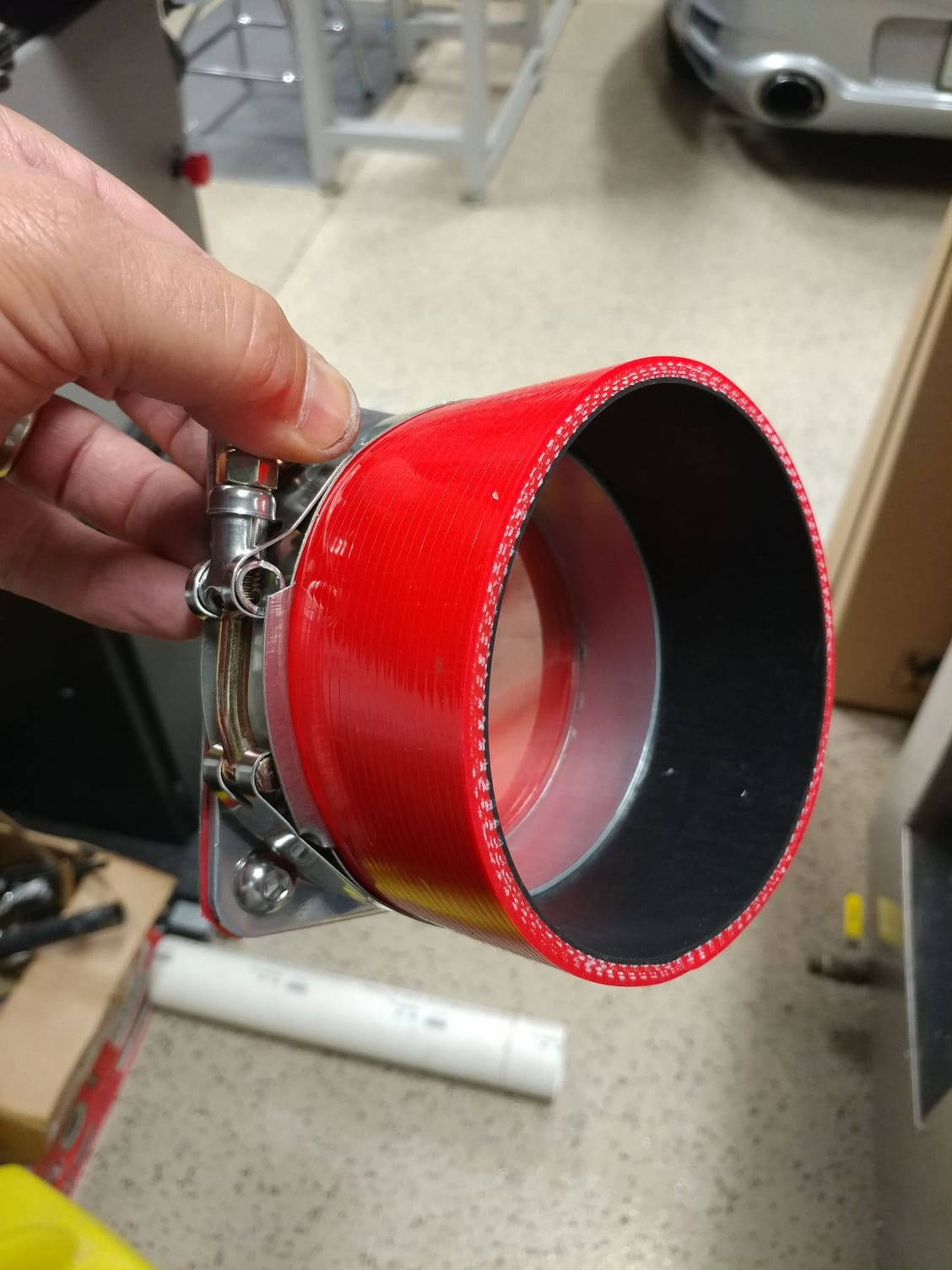
Then I cut a mandrel bent 90 degree Spectre polished aluminum pipe to go from the airbox up to connect to the other piping. I didn't change anything from the supercharger inlet to the first 90 degree silicone elbow from the v2 intake I made, just had to do the piping from the new airbox outlet to get it to connect to the first silicone 90 degree elbow that was there.
The straight section of pipe I cut off the metal elbow I used to make a connector piece to go between the 2 90 degree silicone elbows.
After putting it all together, I realized it was going to be a little too tall so I took the aluminum elbow connector piece back out and put that into my bench vise, turning it into a more oval shape instead of the round pipe - area should be the same and now I have a Hemi intake. Then did a similar thing with the aluminum 90 degree elbow that exits from the airbox to create a little more clearance between this elbow and the supercharger housing itself.
I had a thin circle I had trimmed from one of the silicone tubes when fabbing the v2 intake so I slipped that over the elbow to be a cushion and standoff between the metal 90 degree elbow and the supercharger
Because the airbox is also right up against the power steering reservoir lid, I took a circle of self-adhesive silicone sheet I had and crated a little pad at the contact area so vibrations wouldn't damage or wear through the lid of the airbox.
I fabricated a new block off plate that mounts above the radiator as now I don't need any openings in it anymore since the intake air is drawn in from the wheelwell - dressed it up a little with some red high-temp paint that matches the stripe on the intake Spider.
Here are pics of the process and finished product. I'll do another update after the first drive, but I think it turned out quite well and conceptually should prevent the supercharger from sucking in hot air that has come through the radiator, providing for more dense air and more power.
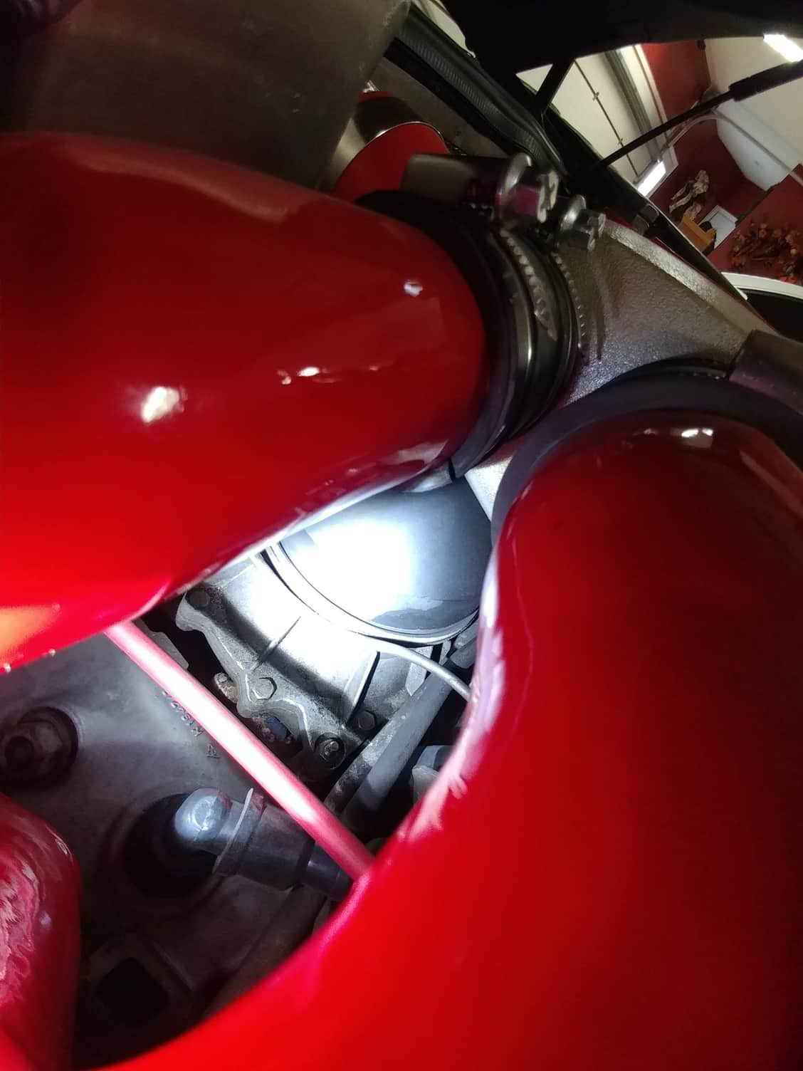
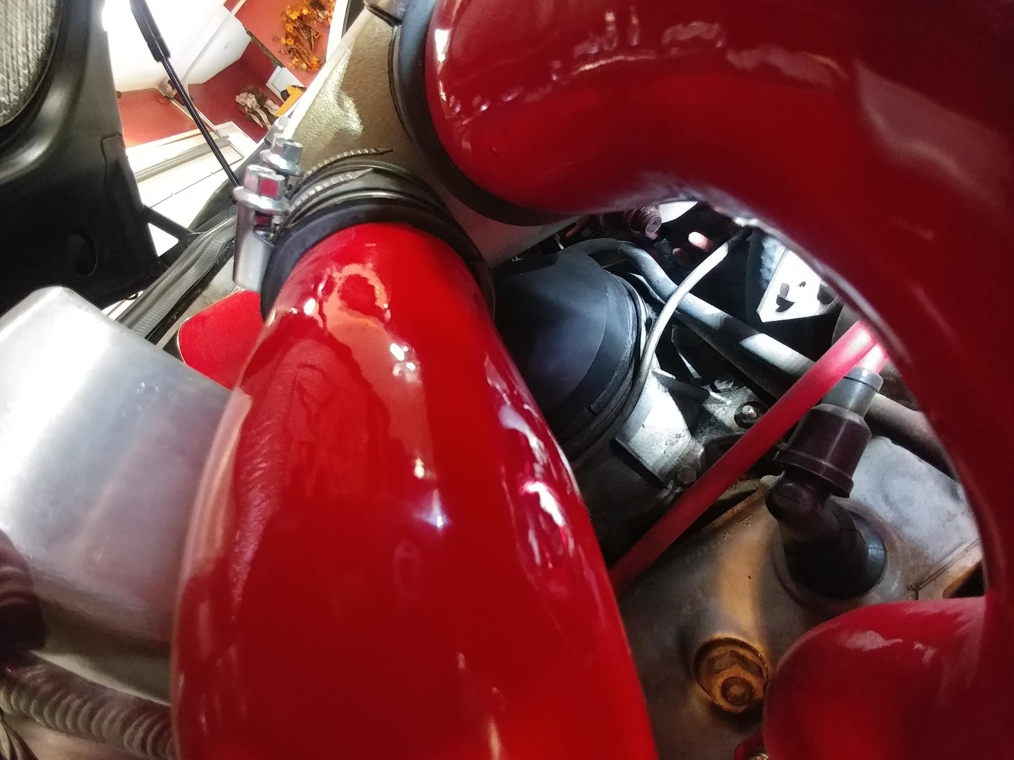
So the new cold air intake didn't solve my boost problem - but I did find the cause. It was a bad seal of the supercharger CIS adapter under the spider intake. Added a seal around it, repositioned it so it would seat properly in the groove, and adjusted the tension rod that goes through the body of the spider intake to put downward force on it.
Look through the spider legs - see how at the front, the top metal piece isn't seated into the groove in the bottom piece and there appears to be some staining in this area on the top piece where a boosted air leak may have been occuring.
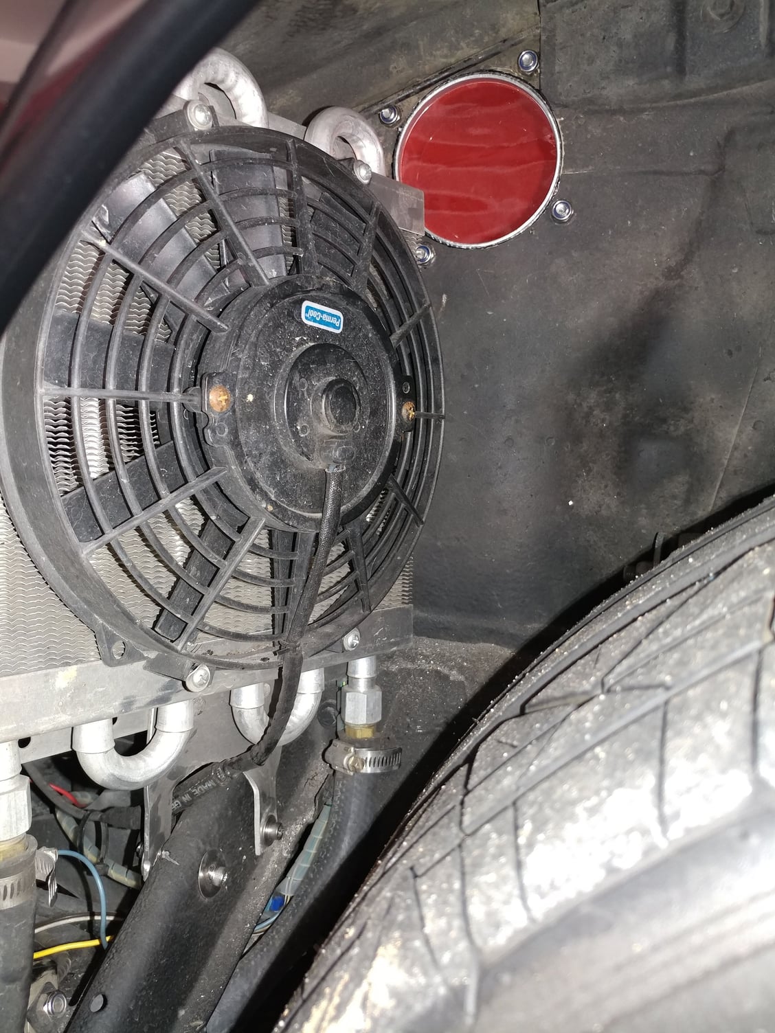
As part of the project where I was trying to regain my lost boost, I realized that neither the Pump for the Heat Exchanger Fluid nor the fan on the Heat Exchanger was functioning so I was really running a Stage 1 setup instead of the Stage 2 setup I had all the components for. I also didn't love the way the wiring for those items, the HID headlights, push/pull radiators fans and controller, etc in that area had been done, so I decided to add a secondary fuse panel and put each of those components on their own fused circuit.
After a couple drives this weekend, that looks to be the primary cause of my issue was - Boost is now 4-5 lbs instead of the 1.5-2 I was seeing previously. The car is much stronger and running extremely well.
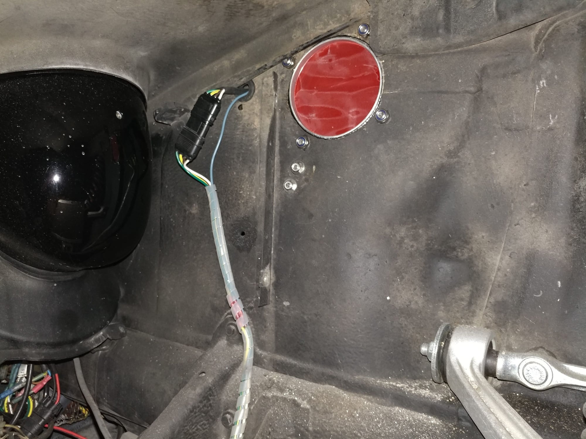
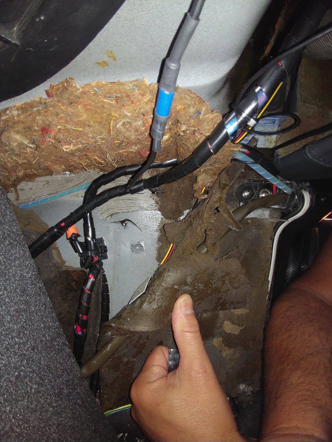
On to investigating the non-working HE Pump & Fan. First off, I didn't realize that the pump used windshield washer fluid from that reservoir as the cooling medium. I haven't had more than 3" of fluid in that reservoir ever, because one of the POs of this car put a ground screw through the metal wall from the inside passenger area, right into the coolant reservoir. When I redid a bunch of the interior wiring, I removed this unnecessary screw and washer fluid started running into the car. Not wanting to risk that happening after it was all done, I just let it drain out to below the screw hole and never filled it up again (4 years this way).
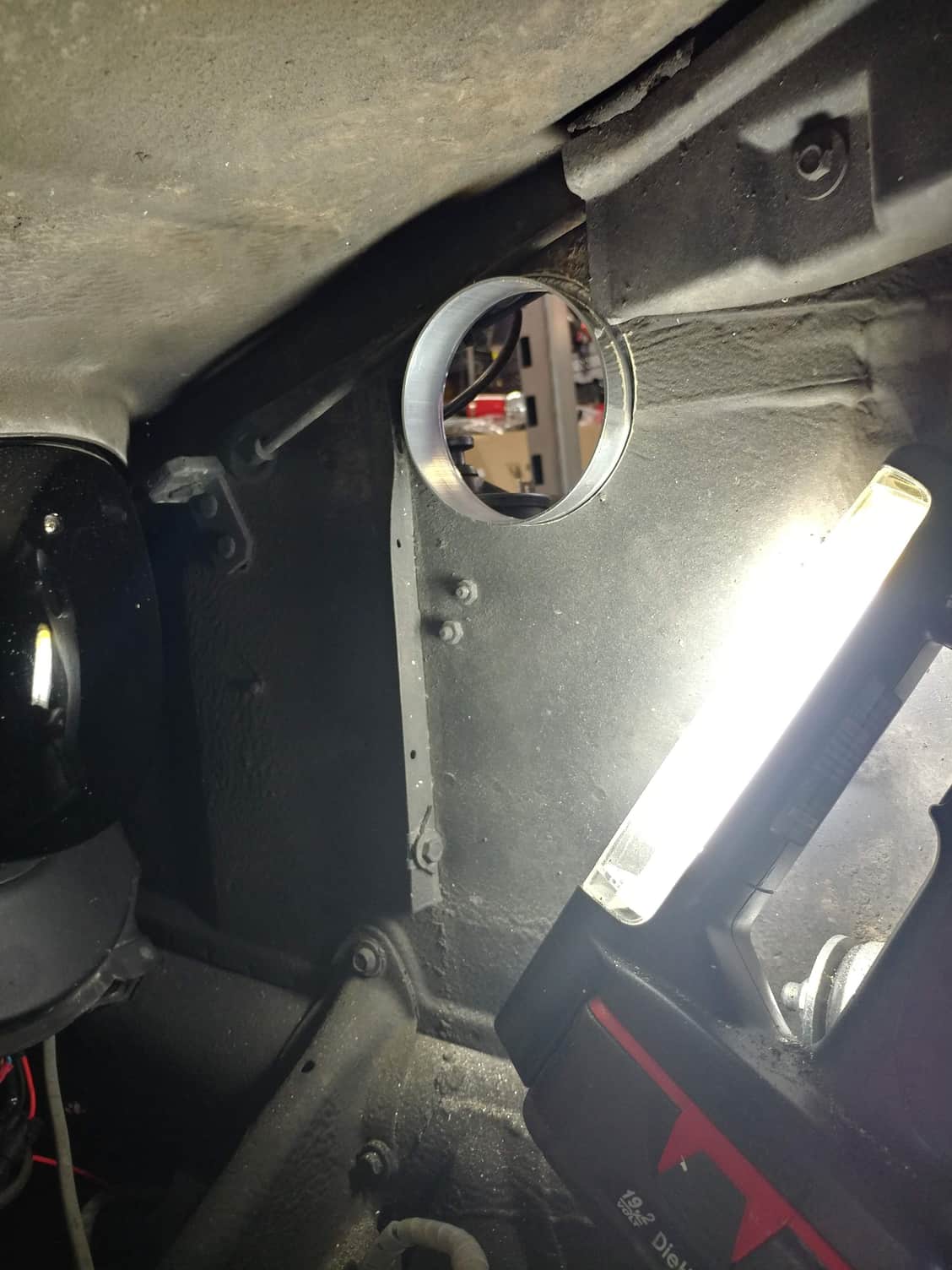
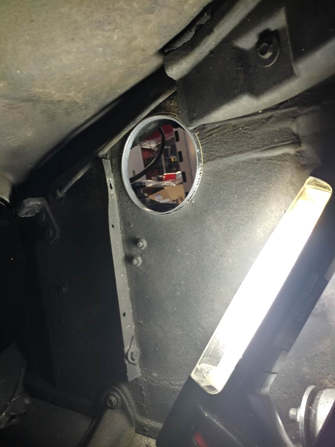
So, step one was to fix that problem. I made the hole in the sheetmetal a little bigger so I could get good access to the screw hole in the water bottle, mixed up some JB Weld. forced it into the screw hole, then sealed up the enlarged sheet metal hole too - reservoir is now water tight now so I can use my windshield squirters and more significantly, have a large fluid capacity for the heat exchanger fluid. Patch is the grey circle in the middle of the photo and behind that is the plugged hole in the reservoir.
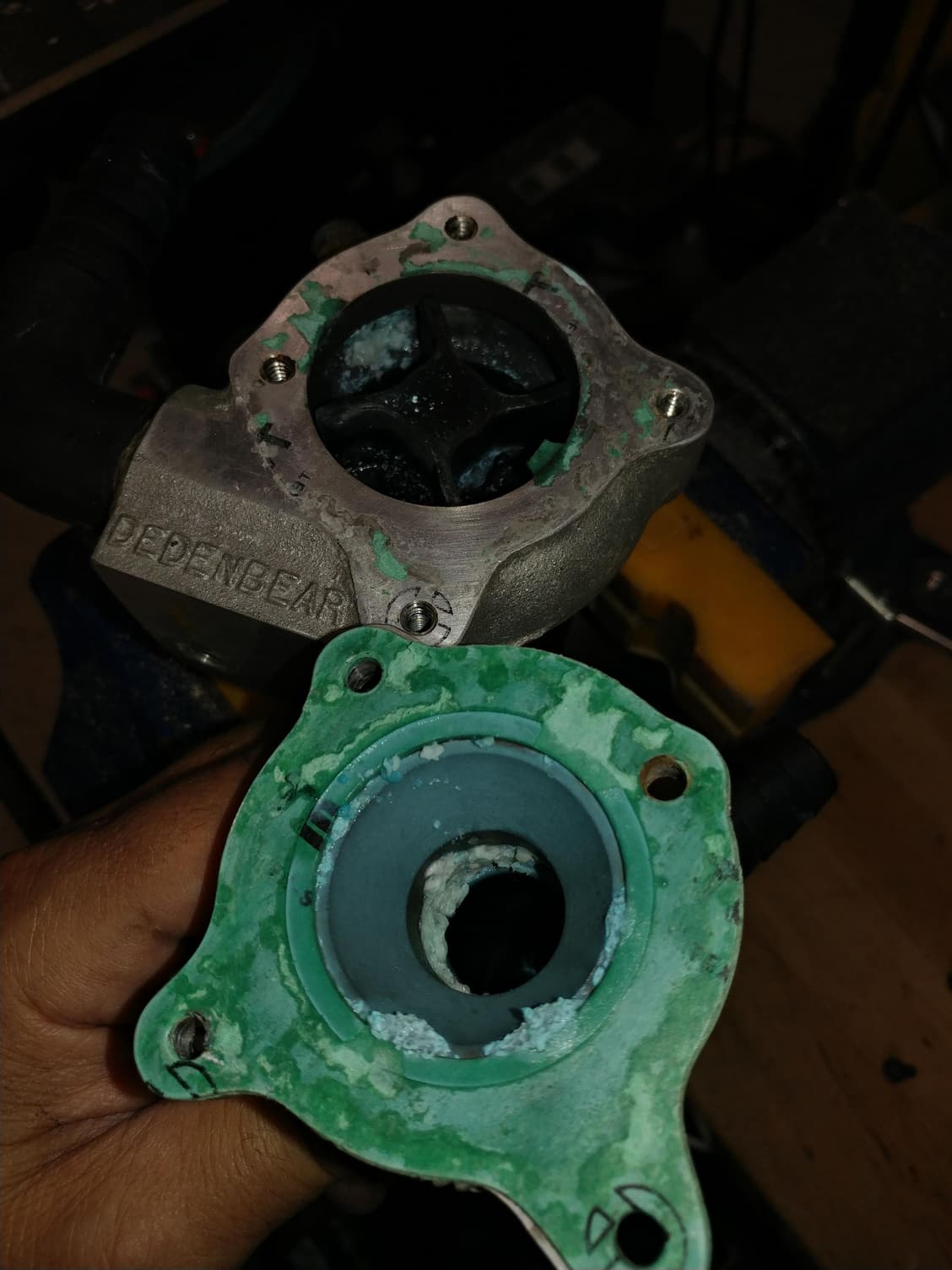
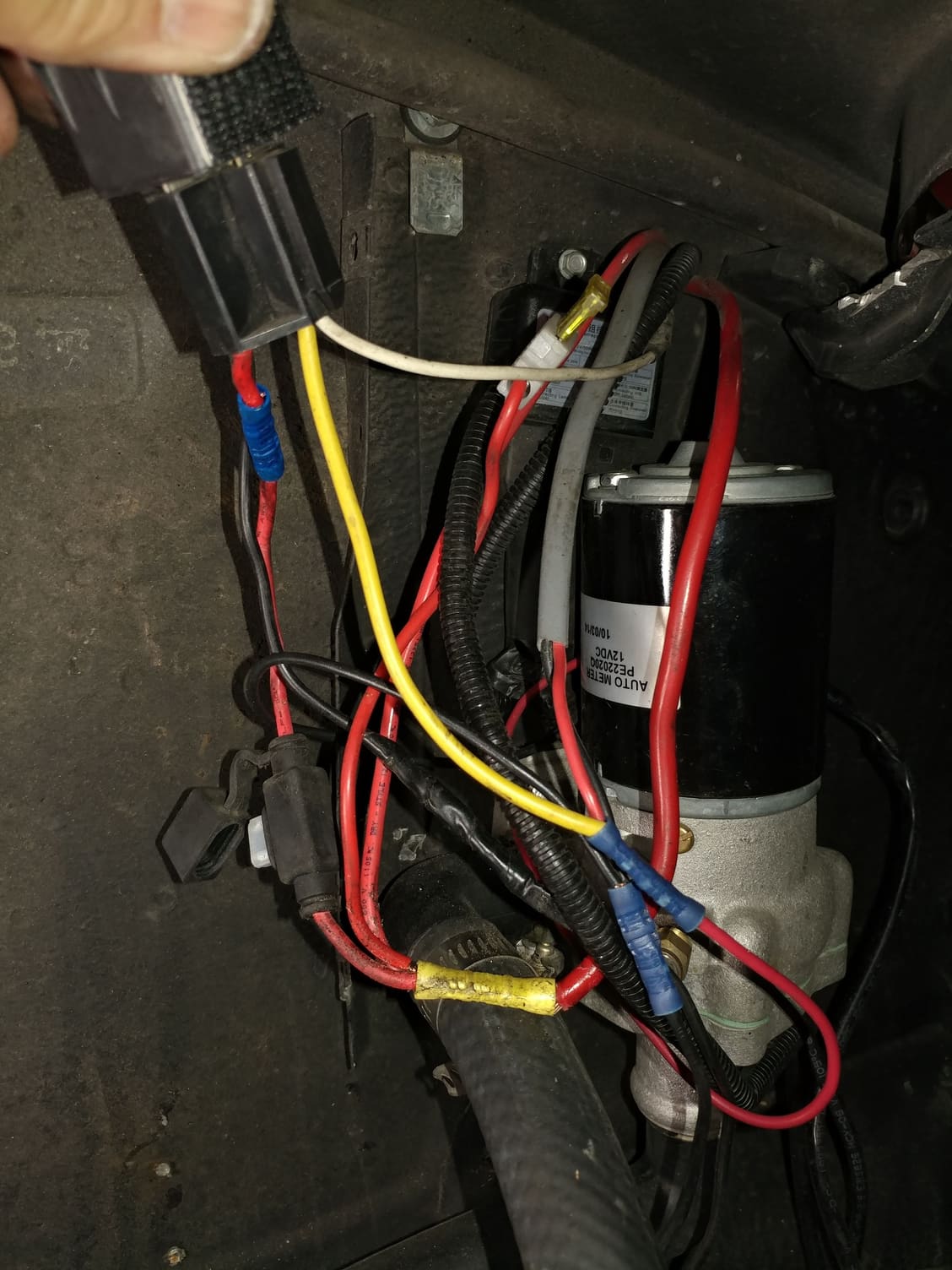
Then I started looking into the pump itself. Put 12v to it directly - nothing. That's not good news. Removed the pump so I could work on it in a better area. Tried it again out of the car - nothing. Apart it comes to reveal this and an impeller that I can't spin by hand.
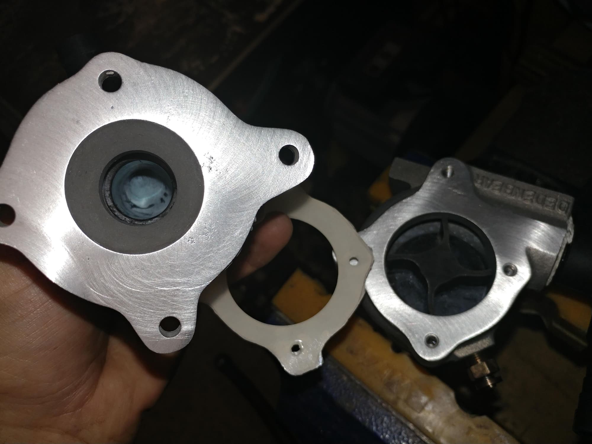
I eventually scraped away enough of the crust to turn the impeller by hand so the motor wasn't seized - good news as this is a high end pump that costs about $400. Soaked the two pieces in CLR overnight, cleaned up the gasket surfaces, cut a new gasket from some silicone sheet material I had, and reassembled.
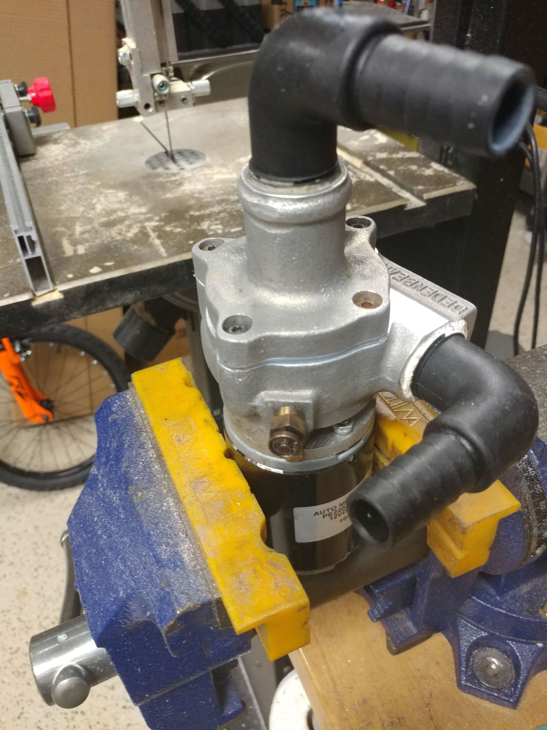
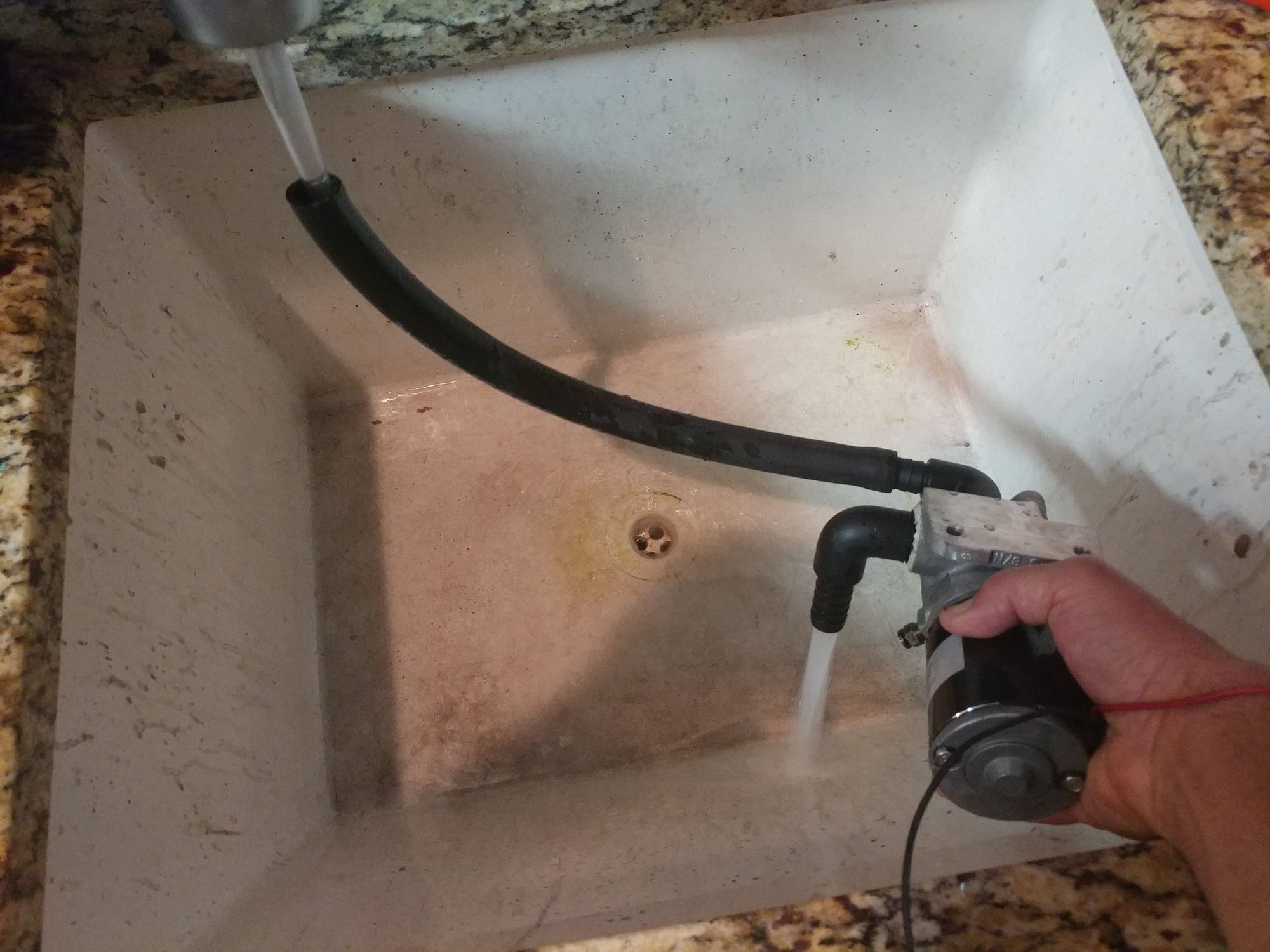
Back in business...
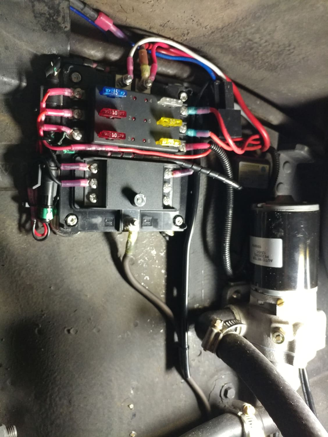
There are so many wires in that section of the car for the HID headlights, air horns, HE pump, HE fan wiring, etc that I wanted to redo how all that is done as multiple things were on shared circuits, etc. I mounted a marine fuse box so each wire can be on it's own fused circuit.
One side got a Constant 12V feed from a wire I run from the jump post (this is for the push/pull fan controller, Xenon lights controller, etc) and another side of the fuse box got a switched 12v feed. I used an SPDT relay, took one lead from the constant side input post of the new fuse box to supply pin 30, took a trigger lead from the switched side of the other auxiliary fuse box I installed down in the passenger footwell area adjacent to the other fuse & relay panels, then use the other leg of the relay from pin 87 to supply the switched side of the new fuse box, and all the switched circuits come off of that. The relay is an 80A so won't have any trouble supplying power to that side of the fuse box for the few switched circuits (HE fan, HE pump, etc).
This is what things looked like when I started.
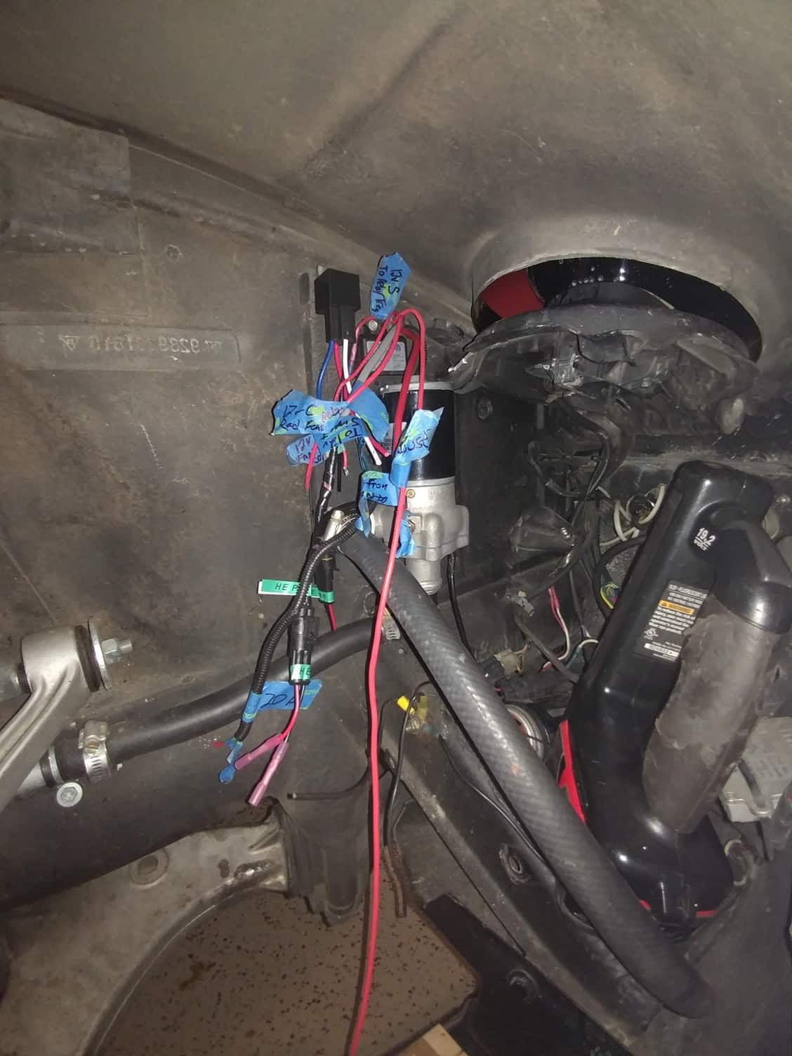
Reinstalled the fixed pump and labelled all the wires ...
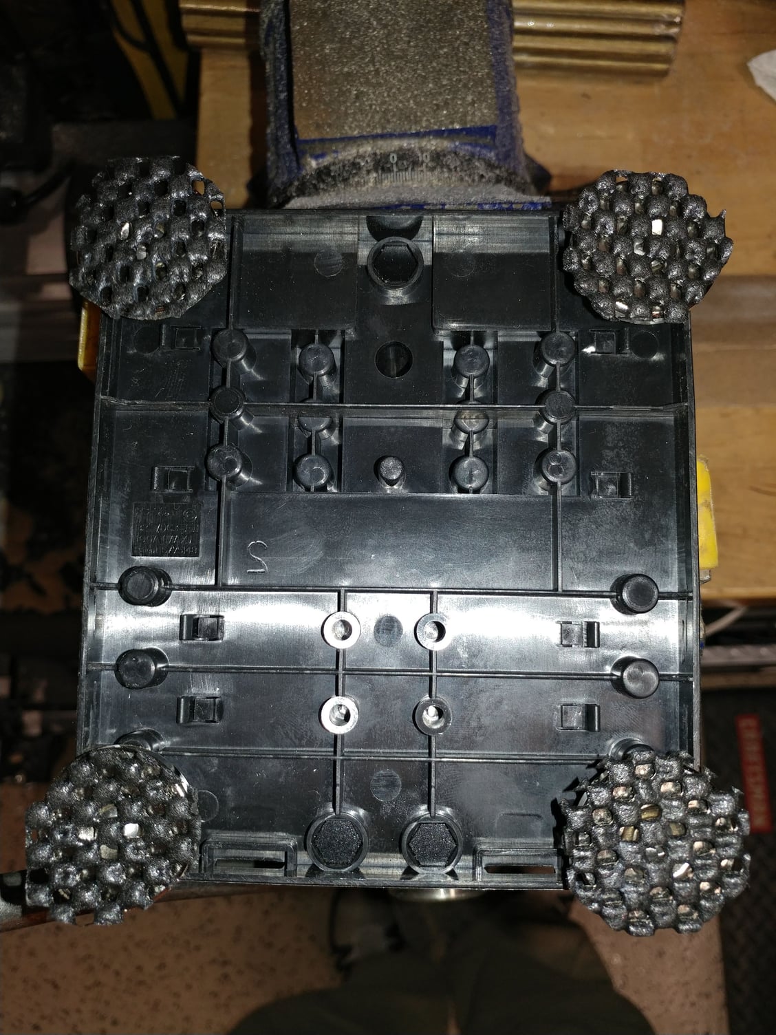
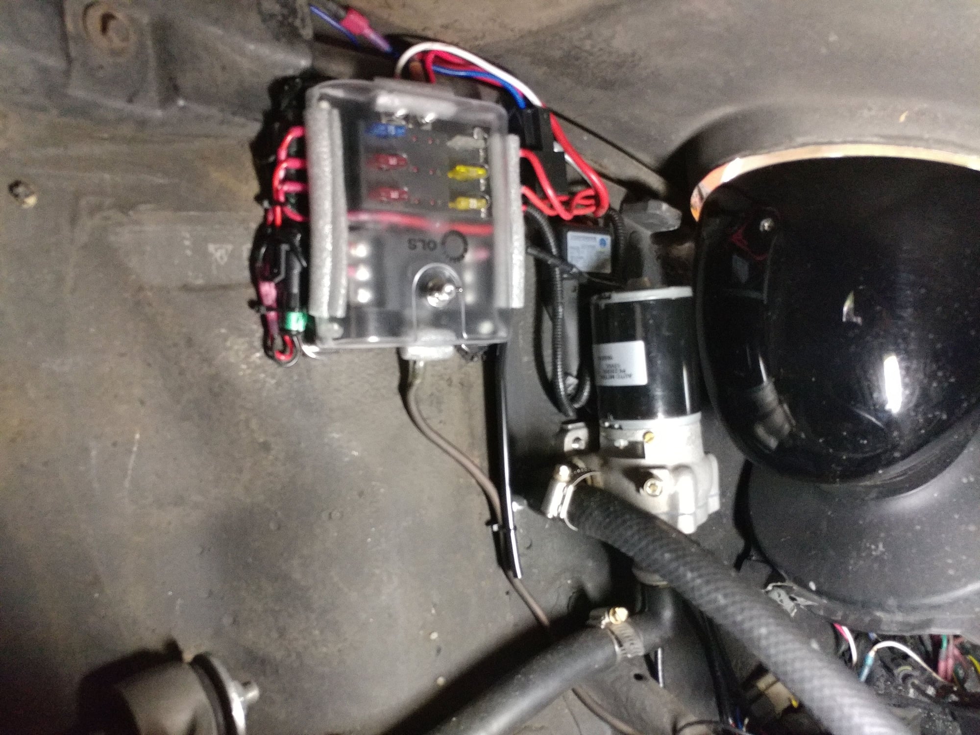
I mounted the fuse box to the inner fender wall using 4 super strong 1" Neodymium magnets. There is so much stuff mounted on the engine side of that fender wall that I didn't want to risk drilling holes to mount the fuse panel and hitting an A/C line, a wire, or some other critical component. To make sure the panel doesn't slide around at all, I cut 4 circles the same size as the magnets from rubberized mesh tool drawer liner and put them between the magnets and the fender - it's rock-solid. I modified it to be quite a bit lower profile than the original design by changing how the cover mounts and by trimming down a good bit of the depth of the plastic cover, then reshaping the profiles where the cover goes over all the connections, and used some foam weatherstripping to seal up the edges of the fuse panel. Tire isn't anywhere near it, even at full lock and suspension compressed. I updated the Customizations Manual I keep with the car to reflect the wiring colors, where they go, how the circuits are fused, etc.
Here's the finished product.
I actually can't remember the car running any better than it did this weekend. With the closed airbox, the engine noise is quieter so I tend to run the RPMs up a bit higher and that's where the max boost is achieved. Should be getting less heat soak with the new closed airbox; I also now have a functioning heat exchanger for the intercooler to make the air even more dense, and sealed up a significant boost leak so that cooler, denser air is now making it into the engine. Wideband AFR gauge showed 11.2-14.5 in all conditions so on the richer (safer) side and not getting too rich or too lean.


 01-05-2016, 12:27 PM