When you click on links to various merchants on this site and make a purchase, this can result in this site earning a commission. Affiliate programs and affiliations include, but are not limited to, the eBay Partner Network.
So I decided to do a polished finish and the media which you can still see is partially trapped in the bolt holes was a bit course for aluminium so that means it shiny but not super shiny. This is good as it means they won�t get as dirty and mark from greasy hands etc.
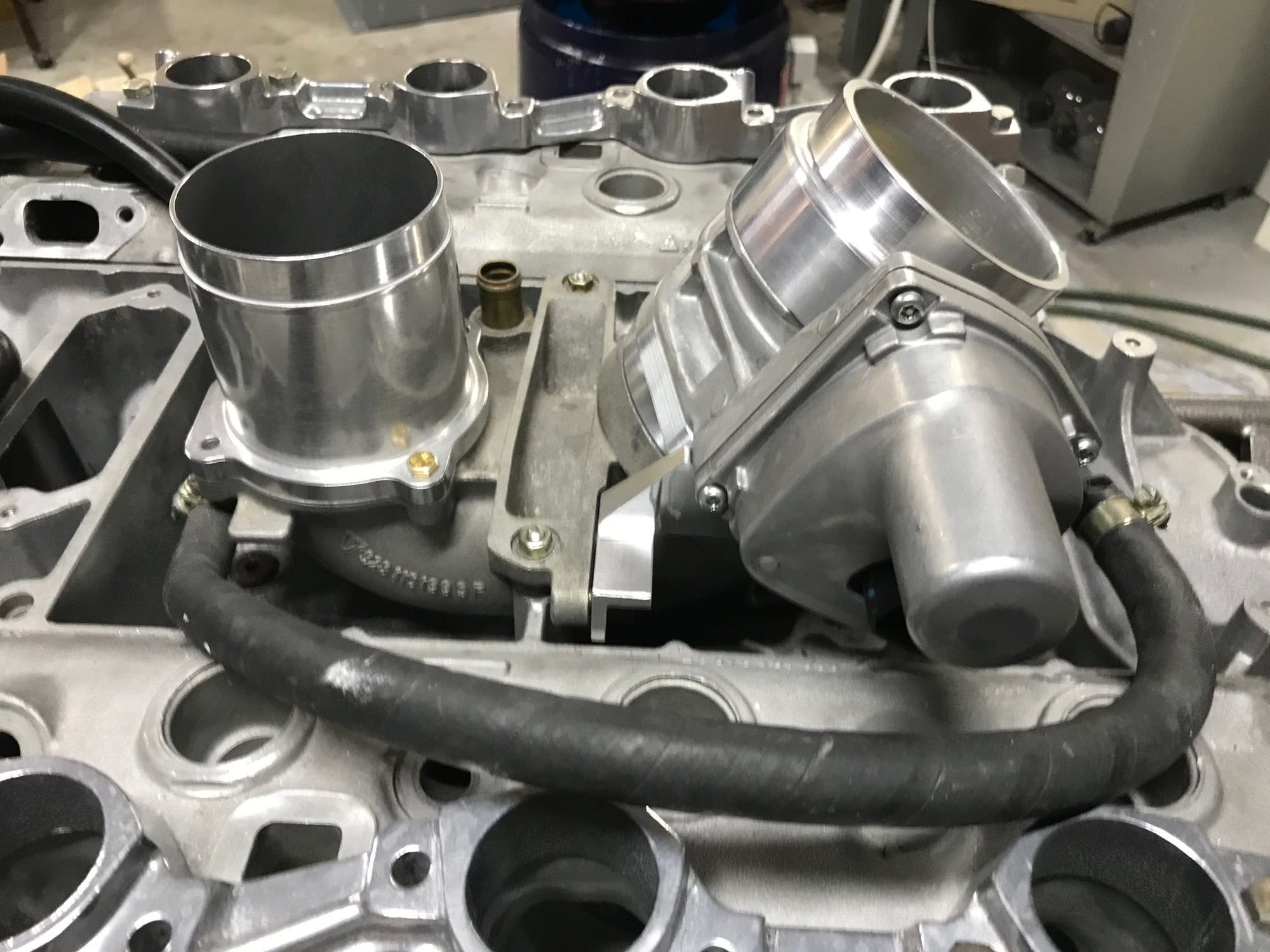
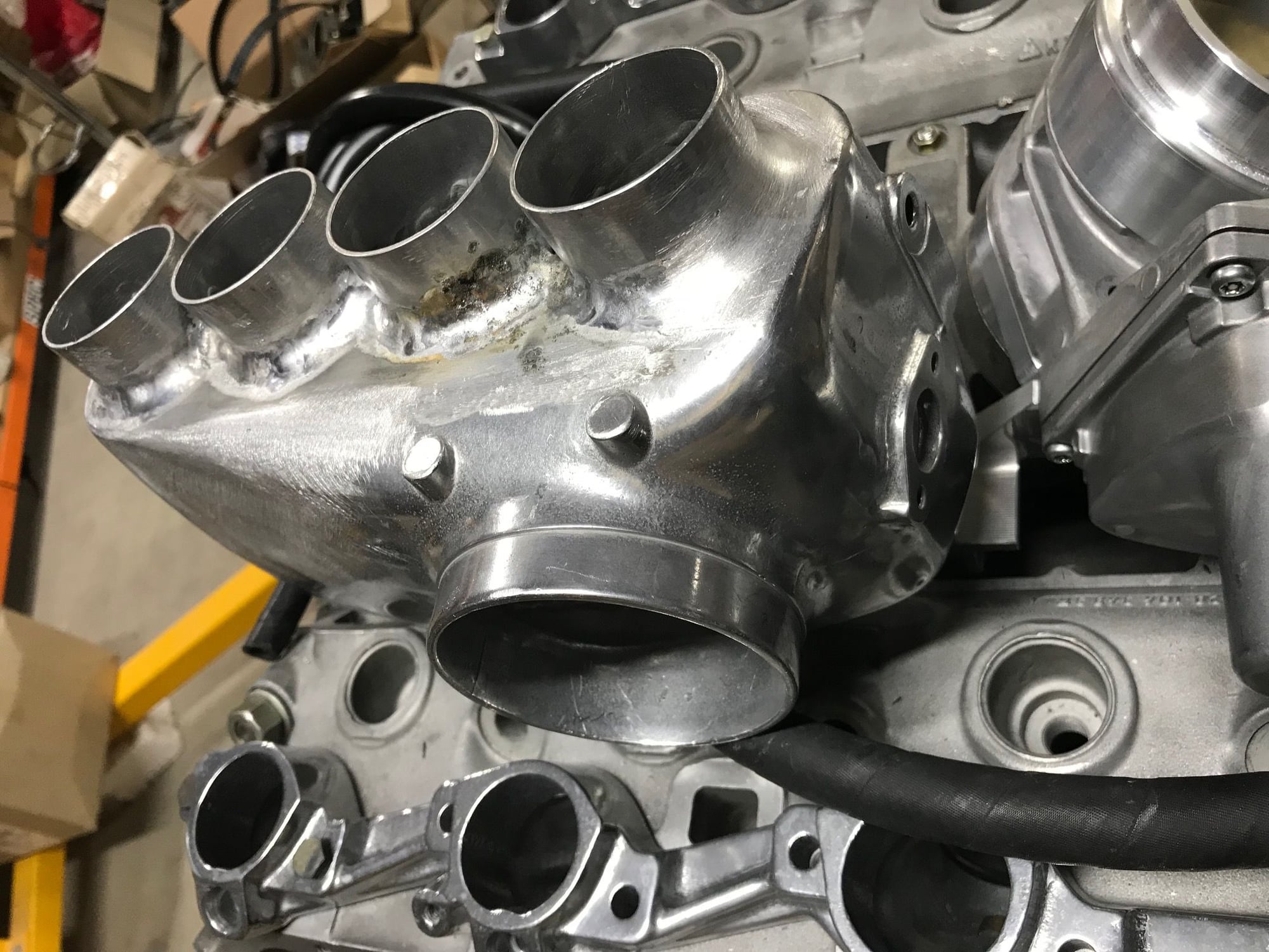
Long awaited updates, still not finished but you will get a good idea of the concept and design now. It still needs some pipe work rerouted and the MAP sensor.
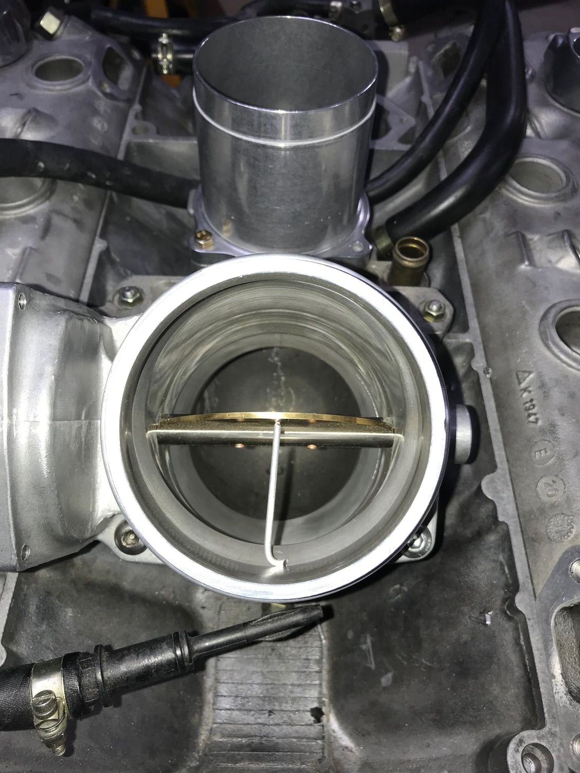
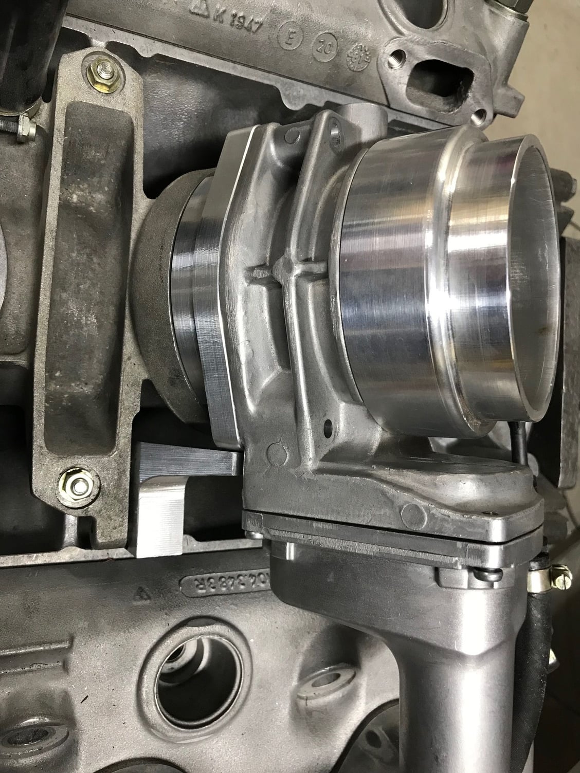
Now a 90 mm throttle, these pieces are made to fit correctly regarding the changing diameters in the inlet tract.
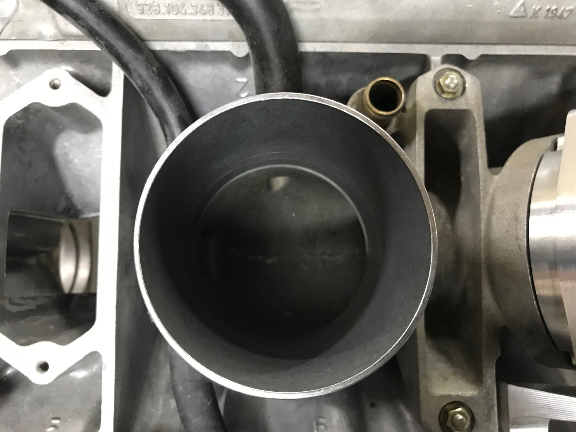
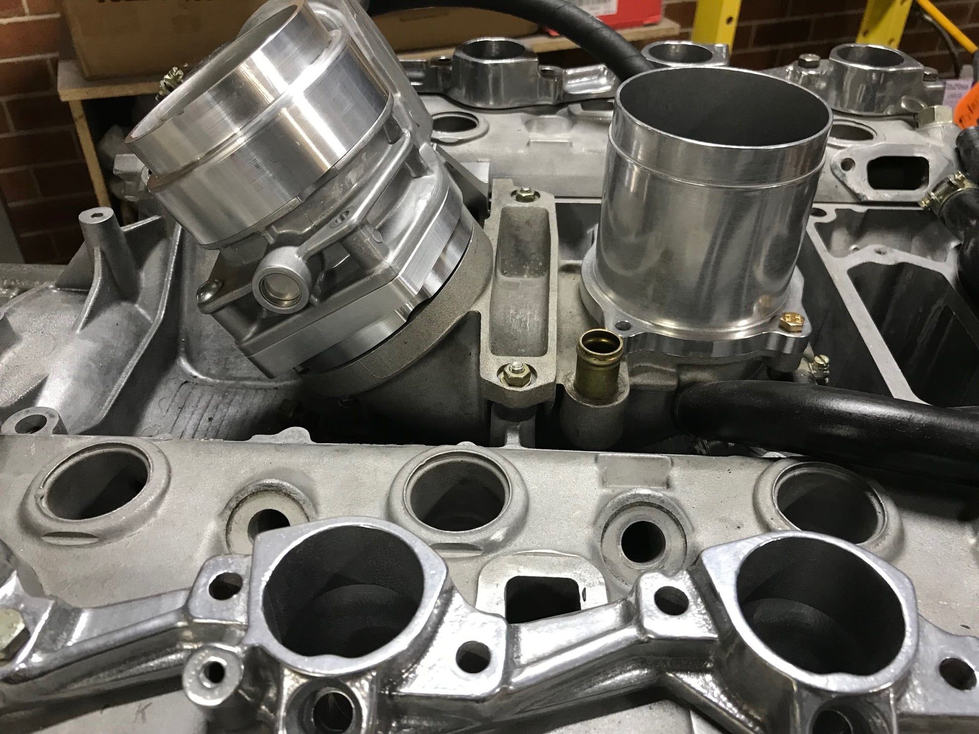
No throttle anymore, this piece has a slight taper from memory.
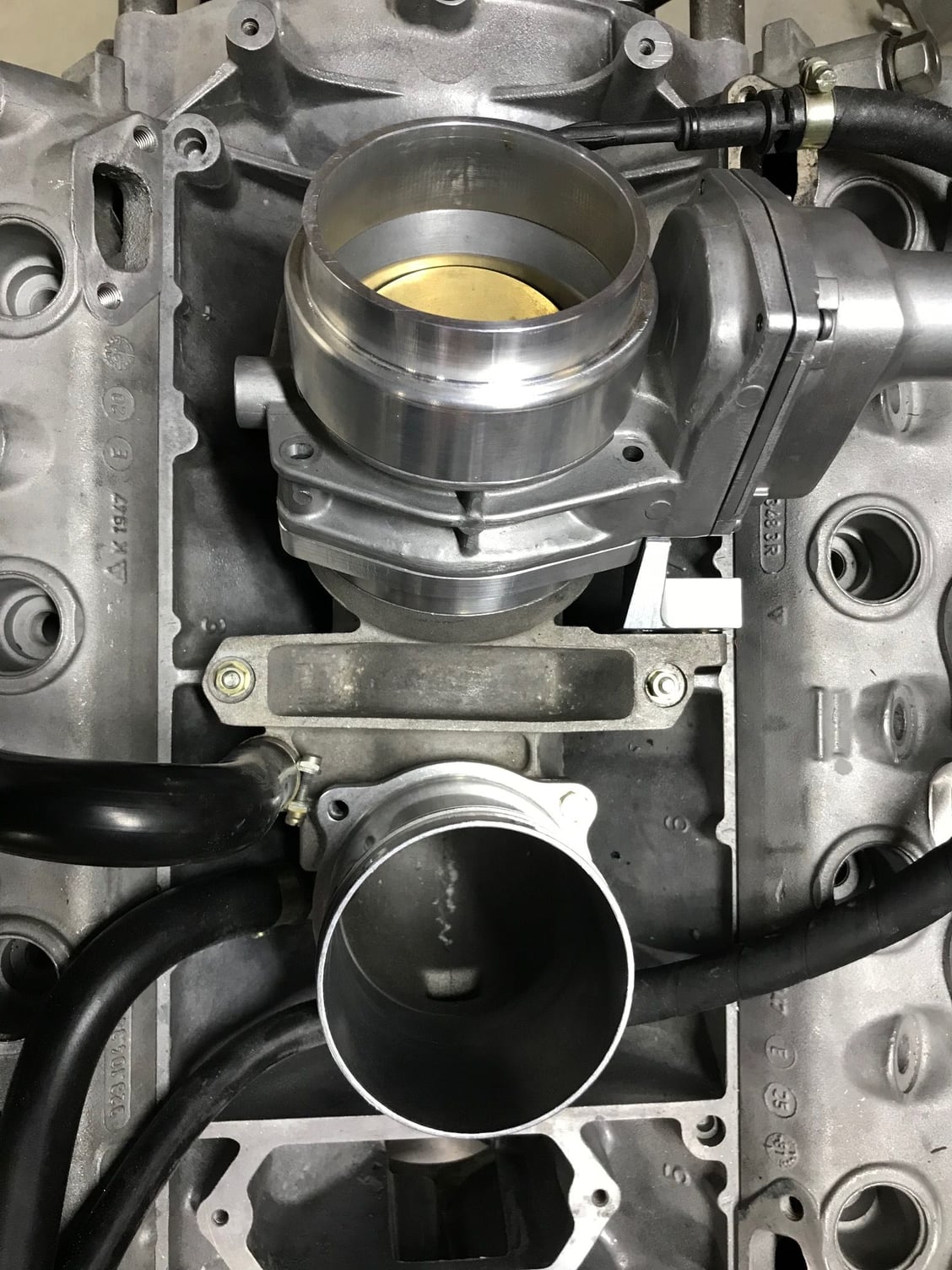
Side view showing the locating piece that stops rotation of the throttle body. It attaches where the pressed metal piece used to reside.
The goal was to be able to use the factory rubbers and mounts and the air filter and plenum still locate with the factory rubber joiners
Ran out of gas and solder. Hence the burn on the second runner. MAP sensor will locate on the front of the plenum.
Flange plates have also received a polish before welding.
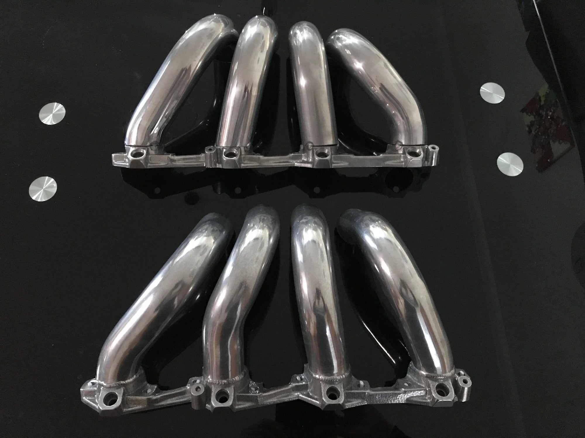
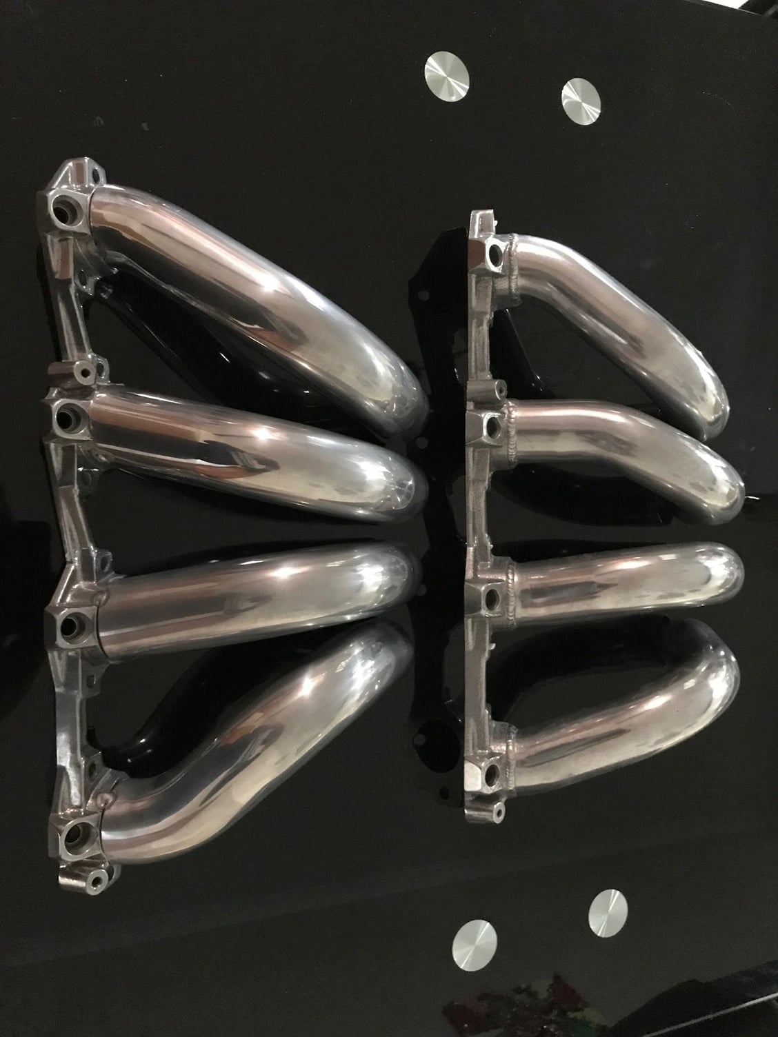
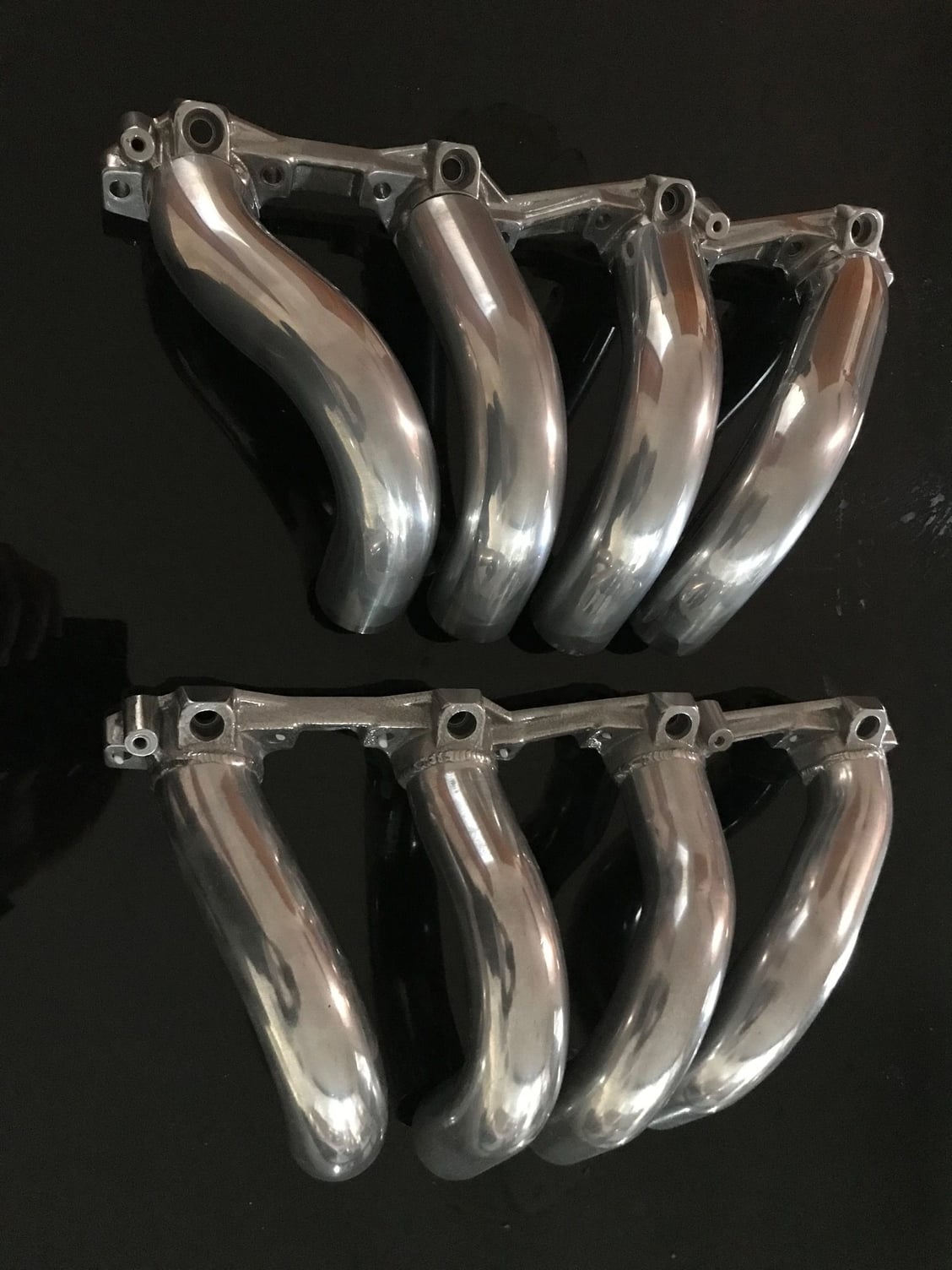
So a little update, my welder cannot weld these tubes to the flanges well enough, it�s a combination of things, first is my welder which is a Miller but a small 210 amp model does not have the EN/EP adjustment, second as I mentioned I don�t have helium argon mix as the gas and third and I�m not sure how much this is a factor but myself as the welder. So next week they will be done but they are tacked and we can compare the larger manifold to the earlier smaller manifold for the 5.0 litre. I found that interesting.
5.35 manifold on top, this is the best photo to see the difference in the straightness.
5.0 manifold on the right
The 5.35 manifold is side specific now, the back is higher than the front.
The 5.0 was made like the factory manifold in that it could be run on either side.
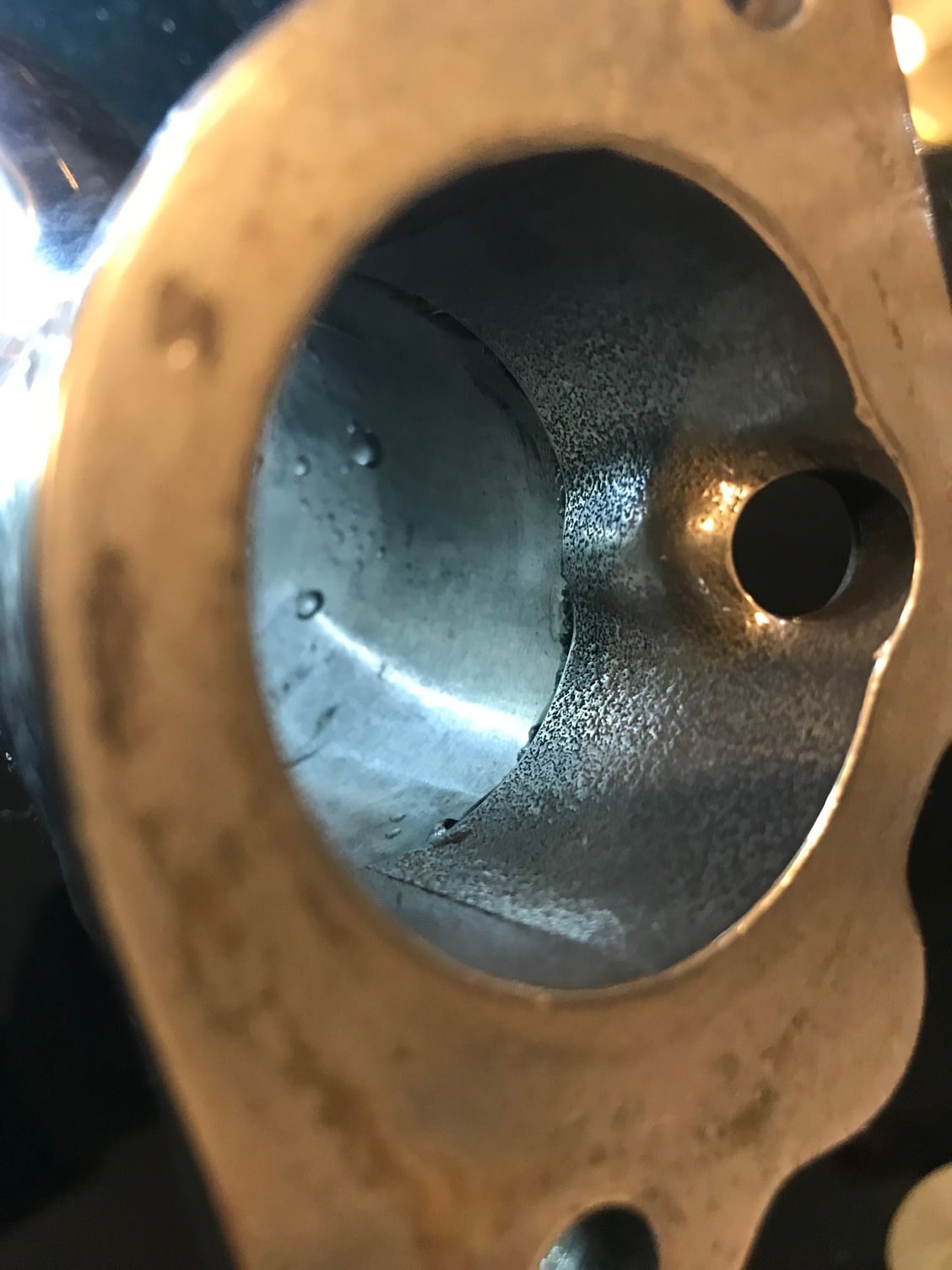
Ok, so a little progress on this one, I had the flanged welded which was an awkward job, the penetration was about 80%, he said and I agree, grind out the excess material and then we'll have a look at welding them from the inside on any spots where there should be more material.
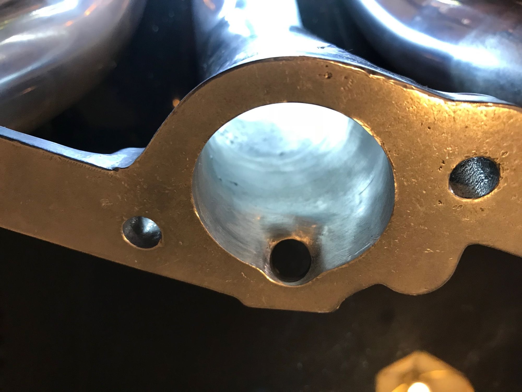
Starting, point, quite a lip. Now pretty good, still need to port match
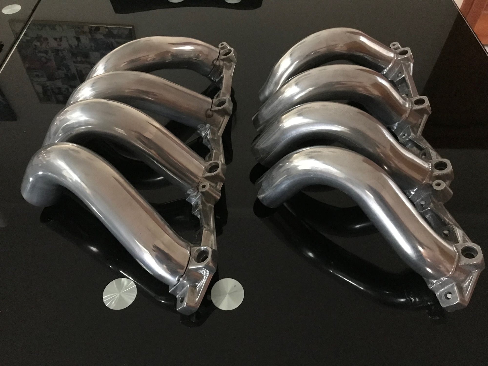
Ok, so you will recall the previous manifold was too small for the bigger 5.35 litre engine, those pipes were 1 7/8" and these are 2" and we're talking O.D. with 1.6 mm wall, so internally the smaller manifold was approximately 43.5 mm and this one is 47 mm. Or approximately 17% bigger in volume, the engine is 7% bigger and the airflow that the heads are capable of flowing is approximately 10% more. The 17% in extra volume is a bit deceptive as the runner tapers at the flange down to 43 mm which is the port diameter of the head up from the stock 41 mm.
We know that the modified smaller intake and plenum knocked off between 5 and 10 CFM on the smaller engine's heads but they knock around 30 CFM+ off on the bigger 5.35 litre heads. The graph below was in another of my threads but it might be quite useful here.
So that graph is at 10" of water I will convert to 28" and what we have then is that basically a straight pipe 42 mm (with tapered throttle) was flowing around 285 cfm. My larger heads flow in the 270+ CFM range, so I think there is a reasonable chance from this antidotal evidence that the new manifold will support these larger heads well. I base that off, improved plenum, which is larger and has proper bellmouths, the larger runners which have nicer smoother bends. I would hope that the manifold and plenum in a standalone situation would outflow the heads. This would then give the desired results, it's really been a mountain of work and it not over yet.
If your 80% external weld gives enough mechanical strength to the join could you use an epoxy to fill and smooth the join on the inside? This project is awesome BTW!
If your 80% external weld gives enough mechanical strength to the join could you use an epoxy to fill and smooth the join on the inside?
Epoxy is great stuff, it's just I'd worry about it eventually falling out. In fact the additional welding may well be worrying about nothing. However that is the story about me... Thanks for the compliment too, it helps me keep some enthusiasm.
If your 80% external weld gives enough mechanical strength to the join could you use an epoxy to fill and smooth the join on the inside? This project is awesome BTW!
I have used Belzona 1111 Super Metal in order to rise the floor of the intake port and increase the small side radius for improved flow on several engines. Having a few screws bolted to the head as reinforcement the Belzona will stay in place but there is always a risk however very small it will come off.
�ke https://www.belzona.com/en/products/1000/1111.aspx
Last edited by Strosek Ultra; 09-23-2018 at 12:31 PM.


 08-17-2018, 06:52 AM