
How to do the boosted car crankcase breathing right
 04-05-2014, 07:37 PM
#106
Nordschleife Master
The only check valve I can think of on the breather system is on one of the ports on the foot of the oil filler neck, in the pre-GTS style (I think 92 GTS had it still, removed after that). The metal oil filler neck used on early 32V cars also had it - but the check-valve on those cars is a plastic insert which fits inside one of the ports on the metal filler neck - same location as the S4 one IIRC.
From memory, the check valve is on the long brather line that runs from the filler neck to the plastic Y on the maf boot (so the aft of the two ports on the filler neck base).
From memory, the check valve is on the long brather line that runs from the filler neck to the plastic Y on the maf boot (so the aft of the two ports on the filler neck base).
 04-05-2014, 09:58 PM
#107
Nordschleife Master
Thread Starter
The only check valve I can think of on the breather system is on one of the ports on the foot of the oil filler neck, in the pre-GTS style (I think 92 GTS had it still, removed after that). The metal oil filler neck used on early 32V cars also had it - but the check-valve on those cars is a plastic insert which fits inside one of the ports on the metal filler neck - same location as the S4 one IIRC. From memory, the check valve is on the long brather line that runs from the filler neck to the plastic Y on the maf boot (so the aft of the two ports on the filler neck base).
04-06-2014, 01:14 AM
#108
Electron Wrangler
Lifetime Rennlist
Member
Lifetime Rennlist
Member
If there is no check valve in the oil filler neck, like with the GTS, what's to prevent the closed throttle circuit from drawing the air directly from the hose that connects the oil filler neck and the MAF elbow? As far as I see nothing. If so, there's not fresh air circulating in the crankcase, removing water and fuel vapors.
*on a GTS with no valve any net vacuum will create some flow so it will flush at lower RPM.
At idle there will be flow into the TINY intake vent which will be blowby gasses from the crank & cam covers and some component of fresh air drawn from the cam cover vent on an S4. On a GTS there will be higher percentage of fresh air due to the shorter more direct path to the throttle body - but a GTS will start to flush sooner at just off idle conditions so it balances out a bit.
Whenever there is any blowby (virtually always) there will be some net flow out in addition to any fresh air entry (regardless how direct & bypassing the flush path might be). So I contend that even on a GTS some minimal flushing will always happen at idle - however I don't think this is the primary flushing mechanism - it wouldn't really make sense, you want flushing at midrange cruise levels not at WOT or idle since those two are less frequent cases that may in fact not be present for long running periods.
I think it was a clever conceptual idea (not that they claim this in the patent) - but it's likely too sensitive to flow rates to survive the engine evolution changes. You want the cam cover vent to be a flush intake most of the time, and the separation strategy to work when it isn't. Neither seems to be true on a GTS.
Now if the center throttle body Y port isn't an eductor - then what is the point? a single big port with a separate external T does the same job - likely rather better.
BTW the question on the cam elbow restrictor/orifice may get answered in this thread: https://rennlist.com/forums/showthre...eferrerid=6055
Alan
Last edited by Alan; 04-06-2014 at 06:53 PM.
04-11-2014, 03:39 PM
#109
Nordschleife Master
Thread Starter
Just got the shipping notification for the blowby sensor that I ordered. It's this fairly simple system from Performance Trends:
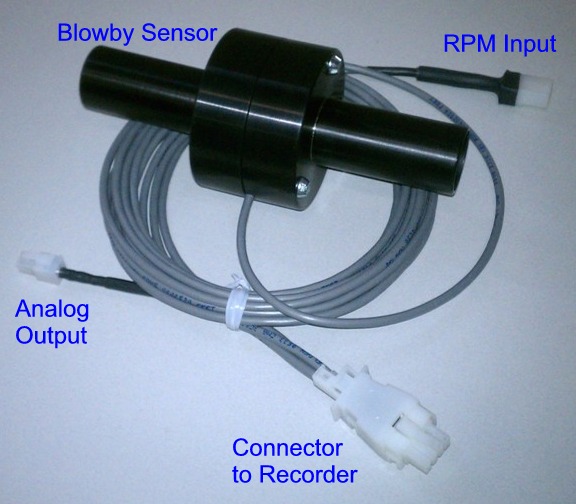
The operating principle of the sensor is fairly simple. There's a calibrated orifice in the middle and two static pressure pickups. The orifice accelerates and restricts the flow by a small amount, which is registered as a pressure differential between the two static pressure pickups.
The first thing we'll do with this sensor is to measure and record the total blowby from the engine per load and rpm. After that, we'll start experimenting a bit to figure out the cycle average flow rates between various points in the crankcase.
A note on my car's blowby and oil ejection issues. When we first strapped the car on a dyno, we got some oil out of the breather system. Then I drove it for 1000 miles straight with both eyes on the radar detector, and after that we haven't ever seen oil come out of the breathers on the dyno. This car has been dynoed fairly extensively with very different settings, so there has been ample opportunity for the car to puke out oil if it had that tendency. This is with a KISS system with both valve covers vented with 1/2 inch hose and the oil filler neck with 1 inch hose, then joined, and sent to ProVent.
To some extent, I am trying to solve a non-problem here just to satisfy my curiosity.
04-12-2014, 02:14 PM
#110
Archive Gatekeeper
Rennlist Member
Rennlist Member
Late to the elbow party, but had this in my hands this morning. '91S4 Auto PS valve cover. 2R unrestricted elbow in front, 0R restricted elbow in back, mated to the separator.


 04-12-2014, 02:32 PM
#111
Administrator - "Tyson"
Lifetime Rennlist
Member
Lifetime Rennlist
Member
Which one did you order? I see they come in 6 different flavors.
I see it has the standard 0-5v output for data logging. If the dyno you guys are using has any inputs, it would be interesting to chart it along with the run. Especially if you do a "slower" run with a higher load on the eddie current (or whatever brake system it has).
04-12-2014, 02:44 PM
#112
Nordschleife Master
Thread Starter
The version I got does 0.5-4.3 CFM which is up to about 120 l/min. I will be mostly doing individual hoses with that to find out which direction and at what rate gas flows on average over the 720 degree cycle, so that's the right measurement range.
For the whole engine, it will be a binary measurement: Engine ****ed or not ****ed! ;-)
Yes, it will go on the dyno's data logging.
Yes, the dyno can be programmed to run for a certain time at every cell of the fuel map, for example. Klam eddy current retarders.
For the whole engine, it will be a binary measurement: Engine ****ed or not ****ed! ;-)
Yes, it will go on the dyno's data logging.
Yes, the dyno can be programmed to run for a certain time at every cell of the fuel map, for example. Klam eddy current retarders.
That's a cool piece. Which one did you order? I see they come in 6 different flavors. I see it has the standard 0-5v output for data logging. If the dyno you guys are using has any inputs, it would be interesting to chart it along with the run. Especially if you do a "slower" run with a higher load on the eddie current (or whatever brake system it has).
04-12-2014, 02:50 PM
#113
Administrator - "Tyson"
Lifetime Rennlist
Member
Lifetime Rennlist
Member
The results should be very interesting.
"To some extent, I am trying to solve a non-problem here just to satisfy my curiosity."
This is the #1 reason why my car is not finished. Spending way too much time testing different things just to see "what will happen".
It's fun either way, and I think that is the whole point with these projects.
"To some extent, I am trying to solve a non-problem here just to satisfy my curiosity."
This is the #1 reason why my car is not finished. Spending way too much time testing different things just to see "what will happen".
It's fun either way, and I think that is the whole point with these projects.
04-14-2014, 03:31 AM
#114
Archive Gatekeeper
Rennlist Member
Rennlist Member
Had some time to play with car parts this weekend. I found a couple of filler necks, including an -07, an -08, and an -09 filler neck. Couple of interesting differences:


So the interesting thing is that there is no -08 filler neck in PET, yet the one in the pics above was from the short-lived '91 S4 Auto, engine # 81M 50621 in the Zombie, and lacks the passenger side fitting of the '09 filler neck:

And I had a different -08 filler neck on my GTS, (build date 8/92) engine 85P00656:

Which did have a passenger side nipple near the top, and a bolt in the single opening on the filler base:

in situ in the GTS:

So- 2 different -08 necks, 1 of which is functionally identical to an -07 neck, and 1 which is more or less the same as an -09 neck, but which has a bigger opening in the upper passenger side nipple than the choked-down (4.8mm) opening of the -09 filler neck. Weird.
So the interesting thing is that there is no -08 filler neck in PET, yet the one in the pics above was from the short-lived '91 S4 Auto, engine # 81M 50621 in the Zombie, and lacks the passenger side fitting of the '09 filler neck:
And I had a different -08 filler neck on my GTS, (build date 8/92) engine 85P00656:
Which did have a passenger side nipple near the top, and a bolt in the single opening on the filler base:
in situ in the GTS:
So- 2 different -08 necks, 1 of which is functionally identical to an -07 neck, and 1 which is more or less the same as an -09 neck, but which has a bigger opening in the upper passenger side nipple than the choked-down (4.8mm) opening of the -09 filler neck. Weird.
04-14-2014, 08:43 AM
#115
Nordschleife Master
Thread Starter
Can you get under the separator plates for these filler necks? For the metal oil filler necks that I've looked at recently, there are at least two different kinds of cast baffling setups inside. Do all these plastic ones have a wall between the oil filler and breather compartments that looks like two letter L
's from below, creating a single long, narrow gap passage between the two compartments?
's from below, creating a single long, narrow gap passage between the two compartments?
04-14-2014, 12:16 PM
#116
Rennlist Member
Tuomo,
Probably not too relevant to your thread but I have now modifed my S4 motor's breather setup to something possibly like yours. I have the John Kuhn baffle in the filler neck with all the baffles removed venting via the filler neck through a 1 inch hose to the Pro Vent. I have now modified this by teeing into the cross breather connection and routing this into the outlet from the filler neck. At the moment I route the breather connection at the back of the passenger side cover to the inlet boot as stock but I fitted a check valve to allow fresh air in but not blow back into the inlet manifold. I am thinking of connecting this to the breather assembly at the front. Just trial and error after listening to you folks.
The pity is I modified my S4 filler neck instead of the GTS neck!
Regards
Fred
04-14-2014, 12:38 PM
#117
Electron Wrangler
Lifetime Rennlist
Member
Lifetime Rennlist
Member
I have taken apart and heavily modified a GTS .09 - it no longer looks at all stock - but there are 2 ribs that run alongside the main throat (front to back of car) - that act as strengthening ribs across the open middle section - but clearly also separate the end sections as baffles that go to ~the bottom of the chamber. It's odd that the dual breather ports are both at the same end since the other baffled off section serves no real purpose... There is a narrow slot in the baffle to the used end - you can see the remnant of it - and there may be a small gap remaining at the base of both sides (but small). The slot is approx 5mm wide by 35mm deep.
Its interesting that one of the louvers in the base plate appear to feed the baffled off unused end chamber.... The base plates are glued on (pretty much a one way trip with these)
I opened this neck up as an experiment (I flipped the base plate orientation laterally & vertically & drilled across the close end. I removed almost all the baffles... However you can see how high up the walls the baffles come on both sides/both ends ~right to the top
This config sat on top of a 928 Itn'l crank baffle plate that was similarly opened up in the blocked end (with wings). The whole of the filler neck - all across the bottom and up the neck was filled with copper scrubbies. Goal was massive area and a slow down immediately on entering the bottom chamber via the restricted ports. Never seemed to work as I had hoped... but was certainly quite restrictive - especially to oil filling...
Now long gone history - another failed experiment...
Alan
Last edited by Alan; 04-14-2014 at 01:20 PM.
04-14-2014, 12:52 PM
#118
Addict
Lifetime Rennlist
Member
Lifetime Rennlist
Member
The blow by meter is pretty cool!...not cheap though! 500 bucks??
Guess i over built mine.
Large 1” diameter inlet and outlet to be able to handle 1000+ HP engine
04-14-2014, 01:35 PM
#119
Nordschleife Master
Thread Starter
Fred --
Your system isn't too different from my KISS system currently in the car.
Some questions:
What's the cracking pressure of the check valve you use int he connection between the MAF boot and the rear passenger side valve cover elbow? Do you know if it ever opens in use?
At high manifold vacuum, the hose routed from the intake manifold driver side to the filler neck driver side is supposed to suck a vacuum in the crankcase that then will pull fresh air in thru one of the valve cover ports. Have you somehow prevented it from pulling this air from the ProVent? Furthermore, should you pull cleaned gas post ProVent to this connection or is the oil filler neck gas clean enough?
Where do you route the ProVent outlet?
How did you size the ProVent? Is it 200? How much hp does your motor make?
Does gas flow into the valve covers or out of the valve covers in the T-hose that is connected to two front valve cover elbows and the ProVent inlet hose?
Those are all questions that one could ask about my KISS system as well.
Best, Tuomo
04-14-2014, 01:47 PM
#120
Electron Wrangler
Lifetime Rennlist
Member
Lifetime Rennlist
Member
....
At high manifold vacuum, the hose routed from the intake manifold driver side to the filler neck driver side is supposed to suck a vacuum in the crankcase that then will pull fresh air in thru one of the valve cover ports. Have you somehow prevented it from pulling this air from the ProVent? Furthermore, should you pull cleaned gas post ProVent to this connection or is the oil filler neck gas clean enough?
Best, Tuomo
Alan