
How to do the boosted car crankcase breathing right


 03-25-2014, 01:32 PM
#92
Electron Wrangler
Lifetime Rennlist
Member
Lifetime Rennlist
Member
I have no idea how it works or what it's made of. I've opened the hood once to verify I could count two turbos and am not planning to open it again unless the diagnostics computer tells me to! ;-) That said, I assume that it's a rotor running in the end the camshaft what throws the oil down to the pan and lets the air out from the center. But that's an assumption. This document contains literally everything I know about how the system works: http://cqxsdas.gicp.net/SDmedia20100...001_002_en.pdf
Well I do certainly understand the desire to have one to just drive.
BTW that link doesn't seem to work... missing the middle bits
Alan
04-03-2014, 10:52 AM
#93
Nordschleife Master
Thread Starter
Did a tiny bit of research into this. Based on the research, I am guessing that both the passive separator and the active separator were designed with Mahle.
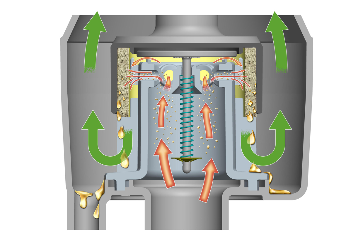
The passive separator is a clever design, avoiding some of the problems with full pass thru filtering, using pressure sensitive nozzle system to keep the velocity ideal, etc. The nozzles accelerate the air-oil mixture to fly out from the center piece at about the right velocity and then the oil hits the coalescing media where as most of the gas can bypass:
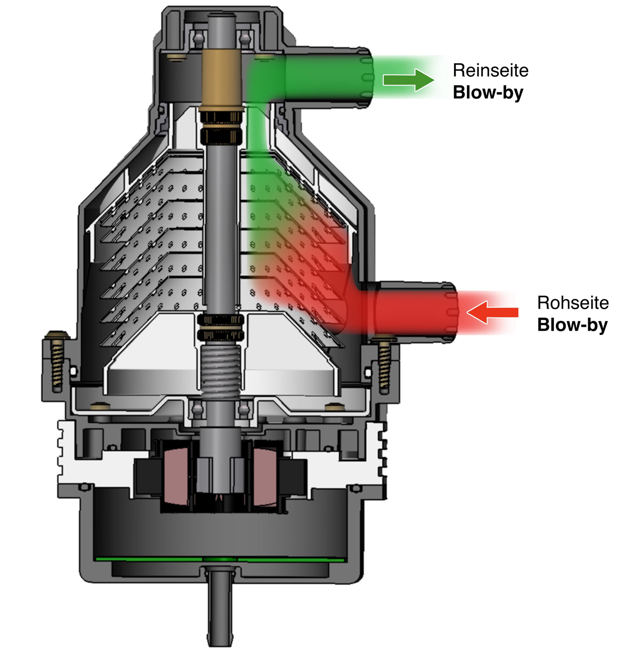
The centrifugal separator can be run by an electric motor, by a shaft such as camshaft, or by oil pressure:
If I were making a thousand of these oil-air separator systems, instead of one, I would get both. Mahle doesn't do series of one, however.
The passive separator is a clever design, avoiding some of the problems with full pass thru filtering, using pressure sensitive nozzle system to keep the velocity ideal, etc. The nozzles accelerate the air-oil mixture to fly out from the center piece at about the right velocity and then the oil hits the coalescing media where as most of the gas can bypass:
The centrifugal separator can be run by an electric motor, by a shaft such as camshaft, or by oil pressure:
If I were making a thousand of these oil-air separator systems, instead of one, I would get both. Mahle doesn't do series of one, however.
04-04-2014, 05:20 AM
#94
Racer
Join Date: Apr 2009
Location: Indianapolis
Posts: 288
Likes: 0
Received 0 Likes
on
0 Posts
I have a couple thoughts to stir up some conversation here with...
The conversations so far (logically) have dealt with air movement within the crankcase. I feel another significant aspect is the rate of oil movement. I have done some research on other engines showing the oil flow rate at high rpm. As a side note, the amount of oil circulating by the pump can not simply be calculated by the pump displacement vs. rpm or whatever because an ever increasing portion is bled off by the pressure control valve as rpm increases. Anyway, at high rpm many engines have only 1 to 3 SECONDS from the time oil returns to the pan until it is picked up again. I have a research paper from MIT showing on a Ford Duratec v6 that a factory windage tray actually caused more aeration in the circulated oil. I can't argue that no windage trays are good, but they also rub me wrong. I believe a good tray would possibly have lots of vertical slats running the length of the motor, sump, or whatever so flying oil would constantly have a surface to slam in to where it can degas and run back to the sump. In other words, adding much of anything to slow down the return of oil to the sump seems bad.
Second, but related, is air in oil and what it does. I realize some of this has been said before, but it leads to my point. When oil is pressurized it can actually dissolve, yes I mean dissolve, up to around 10% air by volume of oil under typical oil pressures. Beyond that bubbles will start to show in the oil. Bubbles in oil are not the same as foam (like shown in the valve covers). Foam, because it is frothy, I think can impede oil return down the drains. Dissolved air can turn to bubbles or possibly foam when it decompresses. My concern here is that it may happen on the way to the rod bearings, not just on 928s. It seems to me the oil problems on the 928 stem from a couple of fairly simple sources. One is the distribution in the ant farm favors letting air in the pressurized oil head straight for the number two main (Death!). Remember even dry sump motors can have healthy aeration problems and distributing aerated oil through the stock passages will result in the same failures dry sump or not. The motor gets air in the oil from its shallow pan, big cranks, etc. and starts pumping aerated oil around. I can't see how some crankcase vacuum could be a bad thing in helping remedy lots of this. I plan to make an insert for the oil fill area of the block similar to what John Kuhn makes and add a reed valve to it, then connect it to an "aspirator" tube in my downpipe to pull a vacuum. This won't work if you're worried much about emissions I suppose. If the motor has a slight vacuum, crankcase pumping is reduced significantly and the oil will be much less aerated. If the oil is less aerated the chances of creating a mocha smoothie in the head are lower and the bearings will appreciate it. If a vacuum is pulled from the block vs. the heads it should be much easier for the heads to drain. With less air in the crankcase and drain-back from the heads better the oil can return quicker with less air to the sump so it doesn't risk being pumped out. To sum up, one problem seems to lead to another with these, and from my (perhaps flawed) logic keeping air out of the motor remedies a good portion of it. I understand a complete vacuum creates other issues like wrist pin and cylinder wear.
04-04-2014, 08:54 AM
#95
Nordschleife Master
Thread Starter
I have done some research on other engines showing the oil flow rate at high rpm. As a side note, the amount of oil circulating by the pump can not simply be calculated by the pump displacement vs. rpm or whatever because an ever increasing portion is bled off by the pressure control valve as rpm increases. Anyway, at high rpm many engines have only 1 to 3 SECONDS from the time oil returns to the pan until it is picked up again.
I have a research paper from MIT showing on a Ford Duratec v6 that a factory windage tray actually caused more aeration in the circulated oil. I can't argue that no windage trays are good, but they also rub me wrong. I believe a good tray would possibly have lots of vertical slats running the length of the motor, sump, or whatever so flying oil would constantly have a surface to slam in to where it can degas and run back to the sump. In other words, adding much of anything to slow down the return of oil to the sump seems bad.
For a large displacement V8's, the air movement inside the engine is dominated by piston pumping pulses. The air movement directly caused by the crankshaft rotation is relatively unimportant. For this reason, I think it is not particularly critical to place the crank scraper and windage tray combos close to the crankshaft.
It is, in my opinion, by far more important to use the trays and scrapers in a way that they prevent the oil that is constantly coming off the rod bearings from rebounding back to the crank. What I believe accomplishes this the best is a windage tray that has slots and/or scrapers that are tangential to the rob bearing orbit, the position in which they will not directly reflect oil to the crankshaft in the first reflection and will stop the oil from returning to the crankshaft after the first reflection from the crankcase. The oil only hits the tray/scraper as a second reflection. There's no reason to expect that such a system would prevent oil from returning to the sump, in fact it will likely allow oil to return to the sump faster because it will prevent additional energy being introduced to the oil movement from the second reflection from the crankshaft.
A much more interesting and difficult question is how the scraper and windage tray system impacts the air movement inside the crankcase. I believe that in our engines, the windage tray design should promote two things in terms of air movement. First, it should promote air flowing down, not up, in the corner oil drains from the heads. Second, it should promote the air flow parallel to the crankshaft to take place below the crankshaft when flowing from back to front and above the crankshaft (either thru the S4 breathing holes or the valve covers) when flowing from front to back. How exactly to accomplish that is the secret sauce...
Second, but related, is air in oil and what it does. I realize some of this has been said before, but it leads to my point. When oil is pressurized it can actually dissolve, yes I mean dissolve, up to around 10% air by volume of oil under typical oil pressures. Beyond that bubbles will start to show in the oil. Bubbles in oil are not the same as foam (like shown in the valve covers). Foam, because it is frothy, I think can impede oil return down the drains. Dissolved air can turn to bubbles or possibly foam when it decompresses. My concern here is that it may happen on the way to the rod bearings, not just on 928s. It seems to me the oil problems on the 928 stem from a couple of fairly simple sources. One is the distribution in the ant farm favors letting air in the pressurized oil head straight for the number two main (Death!). Remember even dry sump motors can have healthy aeration problems and distributing aerated oil through the stock passages will result in the same failures dry sump or not. The motor gets air in the oil from its shallow pan, big cranks, etc. and starts pumping aerated oil around.
I can't see how some crankcase vacuum could be a bad thing in helping remedy lots of this. I plan to make an insert for the oil fill area of the block similar to what John Kuhn makes and add a reed valve to it, then connect it to an "aspirator" tube in my downpipe to pull a vacuum. This won't work if you're worried much about emissions I suppose. If the motor has a slight vacuum, crankcase pumping is reduced significantly and the oil will be much less aerated. If the oil is less aerated the chances of creating a mocha smoothie in the head are lower and the bearings will appreciate it. If a vacuum is pulled from the block vs. the heads it should be much easier for the heads to drain. With less air in the crankcase and drain-back from the heads better the oil can return quicker with less air to the sump so it doesn't risk being pumped out. To sum up, one problem seems to lead to another with these, and from my (perhaps flawed) logic keeping air out of the motor remedies a good portion of it. I understand a complete vacuum creates other issues like wrist pin and cylinder wear.
The block oil filler area is not ideal for a reed valve because the one can't pour in oil. The reed valve channel needs to be somehow separated from the oil fill channel, since the reed valve is supposed to only let stuff out and nothing in. Perhaps you have some other way in mind to fill the oil.
If you get the reed valve to work, then it's relatively easy to route the discharge wherever you want, be that in the exhaust or the intake tract.
04-04-2014, 12:06 PM
#96
Electron Wrangler
Lifetime Rennlist
Member
Lifetime Rennlist
Member
Not sure what you are trying to say by a "Complete Vacuum" here? clearly we are always taking relative to the ambient atmosphere since any practical pump is in some form differential. The other thread descended into 'All Vacuum is Bad' type assertions... what does that even mean?
We'd need to be more precise about what absolute pressure & density levels we mean, and therefore what differential pressure to ambient (and the absolute ambient range we expect) for it to be meaningful.
BTW I think we still have no idea of the effect on longevity (of anything) from increasing vacuum - beyond pure speculation - because no one has done (nor could likely afford) the comprehensive testing to find out. It is quite likely that the effect on longevity could be very non-linear in interesting ways as there are distinctly different effects at play. Then there is the question of the linearity of the effects on oil loss, drainback and performance which are separate considerations from that... Optimization here is clearly complex.
Experiential results will likely come from folks gradually increasing vacuum levels and monitoring results over time starting from positions of relative caution where crank pressure and density don't vary (much?) outside the original design envelope (allowing for what Porsche must have assumed & tested for wrt pressure/density for operating conditions).
Really only time will tell us about longevity issues for these empirical test beds, but data on oil control & performance benefits is immediately available, even if often difficult to quantify absolutely/relatively.
Results in "similar" V8's may be helpful directionally but also need to be calibrated against a 928 configuration - and even down to specific engine variants too...
Nobody said it would be easy...
Alan
04-04-2014, 12:15 PM
#97
Racer
Join Date: Apr 2009
Location: Indianapolis
Posts: 288
Likes: 0
Received 0 Likes
on
0 Posts
I've wondered the same thing on the viscosity debate...thicker oil to possibly by time, but may return to the sump more slowly...especially if it's heavily aerated or foamed. Then again, thicker oil may leave more protection until proper pressure resumes. Who knows.
I agree about the pumping pulses moving air, and that a windage tray design can be botched. I do still think the spinning crank is a big problem though. If the majority of the oil returning from the heads is getting pummeled by the crank and it's whirlwind it seems it would likely exacerbate the problem of aerated oil being picked up by the pump. I agree that a simple tray should have the primary function of protection from air pumping movement. The way you mention have air move one direction under the tray is very fascinating.
I'm a little embarrassed to say this...what is DHBC? I play acronym games with a couple friends of mine, but it will likely result in my being banned for a while here...
Pulling vacuum from the tunnel in the middle of the block is perfect! If I have a separator like I mentioned I will make a tube passing through one portion of it that extends up to an oil fill cap. To get enough flow to let the engine breath I plan to use a read valve from a small dirt bike. The read valve isn't used to create a vacuum like would work on a single cylinder. The vacuum comes from the breather tube. Check this out: http://www.summitracing.com/parts/mo...FcdaMgodE1AAwA The only reason I want a reed valve instead of the old air pump check valves like those kits have is because a reed valve has less forward pressure drop so the aspirator tube can be more effective.
I apologize if it seems I'm diluting your thread or changing its focus any. The oil system and crankcase breathing are so closely tied, and the end result is people want motors that don't blow up. I think a simple breather like I have mentioned would help a lot of people here. In fact (gulp) I think a trifecta of evacuation, an accusump, and modifying the #2 feed in the ant farm would make a fairly immune motor.
04-04-2014, 12:21 PM
#98
Racer
Join Date: Apr 2009
Location: Indianapolis
Posts: 288
Likes: 0
Received 0 Likes
on
0 Posts
Alan I just saw your post. The only reason I mentioned "complete vacuum" was to infer that pulling too much or all the air from a crankcase can be dangerous to a motors life. When I say vacuum I mean pressure less than ambient...so complete vacuum would be absolute zero. I've heard of people with mechanical pumps running adjustable check valves to let air back in strictly to prevent excessive vacuum. An interesting thought comes up from this. With a healthy vacuum source in the block...any air admitted from the valve covers would actually create a downward air flow to work with the oil for once instead of against it.
From what I have seen on some other forums most people won't pull to less that 12 inches of vacuum. How well or thoroughly that relates I have no idea.
From what I have seen on some other forums most people won't pull to less that 12 inches of vacuum. How well or thoroughly that relates I have no idea.
04-04-2014, 12:38 PM
#99
Nordschleife Master
Thread Starter
Based on my logic but not any long-term experiments, the whole idea of modest vacuum hurting 928 oiling is in my opinion misguided. The problem with 928's oiling is too much oil everywhere, with one exception mentioned below, not too little. If one is concerned about wrist pin oiling with direct splash, vacuum increases -- does not decrease -- direct wrist pin oiling from splash. Vacuum may reduce indirect wrist pin oiling from the bore walls, but that's not even used in the ill-designed GTS models. The first inch of vacuum in the 928 crankcase is almost certainly helping everything and hurting nothing.
The crankcase simply has too much oil everywhere, except in the sump! ;-)
Entropy Engineer:
That's what I thought until I saw those Big-3 crankcase simulations. Some pictures earlier in the thread. The pressure differentials and flows caused by the crank spinning are totally trivial in those field graphs compared to piston pulses. The piston pulses are all that matters, given the 5-liter displacement. In 1000 cc motorcycle four banger the crankshaft spinning may be more than a drop in the bucket, in a car V8's it's only that, a drop in the bucket.
DHBC = Dead Horse Beaters' Club.
The crankcase simply has too much oil everywhere, except in the sump! ;-)
Entropy Engineer:
"I do still think the spinning crank is a big problem though."
DHBC = Dead Horse Beaters' Club.
Last edited by ptuomov; 04-04-2014 at 01:26 PM.
04-04-2014, 12:49 PM
#100
Electron Wrangler
Lifetime Rennlist
Member
Lifetime Rennlist
Member
Alan I just saw your post. The only reason I mentioned "complete vacuum" was to infer that pulling too much or all the air from a crankcase can be dangerous to a motors life. When I say vacuum I mean pressure less than ambient...so complete vacuum would be absolute zero. I've heard of people with mechanical pumps running adjustable check valves to let air back in strictly to prevent excessive vacuum. An interesting thought comes up from this. With a healthy vacuum source in the block...any air admitted from the valve covers would actually create a downward air flow to work with the oil for once instead of against it.
From what I have seen on some other forums most people won't pull to less that 12 inches of vacuum. How well or thoroughly that relates I have no idea.
From what I have seen on some other forums most people won't pull to less that 12 inches of vacuum. How well or thoroughly that relates I have no idea.
Sometimes differential pressure matters - for ring sealing (ring oil loss & blow-by) it will make some small difference - for oil & air behaviour in a sealed crank it has it's own little microcosm that really cares primarily about the absolute pressure & density there - ambient outside is largely irrelevant.
I have a mechanical pump and adustable vacuum limiting valves in the heads to limit maximum possible vacuum, but the recirculation loop alone is pretty good at managing vacuum level.
Based on the quite large variable atmospheric component here I think an absolute pressure sensor either in the crank or more simply purely atmospheric that allows vacuum bleed off when the ambient pressure is low is a smart idea (e.g. for high elevation driving) to constrain the size of the absolute pressure range the engine ever sees (ideally for me this would stay entirely within the stock pressure range envelope - but on average notably lower).
On your other point:
For me flowing recirculated air/oil back into the heads while evacuating from the crank was for exactly that reason - unidirectional continual downflow in the head drains. Similarly the VLV's allow fresh air flushing into the heads and down the drains (when they flow). The intent of the VLV's is both vacuum limitation and flushing.
Right now I have them set above the recirculation limit all the time. I will experiment soon with reducing that to allow flushing in mid-range condition @ about 6" Hg. It potentially increases net flow through the separators to be too high so its a bit of a balancing act - flushing is good - overloading the separators is bad.
I know its somewhat unproven still - but I think a vacuum pumped system is quite ideal for a boosted car where the usual intake vacuum driven configurations fall apart. Its quite simple to then recirculate well cleaned crank gasses back into the CAI for an emissions legal (Ex CA) set-up. And on a boosted car you likely already have a non-stock exhaust/ high flow cats - so who needs an airpump these days anyway...
Alan
Last edited by Alan; 04-04-2014 at 03:00 PM.
04-04-2014, 08:55 PM
#101
Nordschleife Master
Thread Starter
Crankcase ventilation system for motor vehicles
US 4753214 A
ABSTRACT
A crankcase ventilation system for motor vehicles comprises a main ventilation system and a safety ventilation system, in which at an air guiding housing of the intake system, connecting pieces are arranged to which the lines of the two systems are connected. So that the connection between the lines of the two systems and the air guiding housing is simplified with respect to construction and also requires little space, a joint connecting piece having connecting pipe sections for the lines of both systems is provided at the air guiding housing. Separate ducts lead away from the connecting pipe sections and extend to remotely arranged outlet openings. The outlet openings of both ducts--seen in flow direction--extend at a distance from one another.
CLAIMS(15)
What is claimed:
1. A crankcase ventilation system for motor vehicles, in which the crankcase gases are returned from the cylinder block and crankcase into an air guiding housing of an intake system of an internal-combustion engine via a main ventilation system or a safety ventilation system for accommodating blockage of the main ventilation system, comprising
a main intake line connected to the main ventilation system and the crankcase,
a safety intake line connected to the safety ventilation system and the crankcase in by passing relation to the main intake line, and
a common connecting piece for connecting the air guiding housing with both the main intake line and the safety intake line.
2. A crankcase ventilation system according to claim 1, wherein said common connecting piece includes respective separate ducts which lead away from connecting pipe sections for the main intake line and the safety intake line, said separate ducts extending to remotely arranged outlet openings, and wherein outlet openings of the ducts, seen in flow direction, extend at a distance to one another and lead into the air guiding housing.
3. A crankcase ventilation system according to claim 2, wherein the connecting piece is developed to be approximately Y-shaped.
4. A crankcase ventilation system according to claim 2, wherein a duct of the safety ventilation system extends as a continuation of a pertaining connecting pipe section and has a straight shape.
5. A crankcase ventilation system according to claim 2, wherein a duct of the main ventilation system surrounds a duct of the safety ventilation system.
6. A crankcase ventilation system according to claim 5, wherein the two ducts of the main ventilation system and the safety ventilation system are arranged eccentrically with respect to one another.
7. A crankcase ventilation system according to claim 5, wherein wall sections of the ducts of the main ventilation system and the safety ventilation system rest against one another along portions thereof.
8. A crankcase ventilation system according to claim 2, wherein a outlet opening of the main ventilation system, seen in flow direction, is arranged in front of an outlet opening of the safety ventilation system.
9. A crankcase ventilation system according to claim 1, wherein a duct of the main ventilation system and an assigned connecting pipe section are placed against one another at an angle.
10. A crankcase ventilation system according to claim 2, wherein a duct of the main ventilation system is developed to be closed at the side that is opposite its outlet opening.
11. A crankcase ventilation system according to claim 2, wherein the connecting piece is inserted into a pipe section of the air guiding housing and is connected with it via a locking connection.
12. A crankcase ventilation system according to claim 2, wherein a duct of the safety ventilation system, with its free end containing an outlet opening, projects with portions thereof into the interior of the air guiding housing.
13. A crankcase ventilation system according to claim 2, wherein an end of the duct containing an outlet opening is arranged outside an interior limiting wall in the area of the pipe section.
14. A crankcase ventilation system according to claim 2, wherein the air guiding housing is formed by an air guiding scoop arranged between an air mass meter and a throttle valve pipe section.
15. A crankcase ventilation system according to claim 1, wherein said common connecting piece is a unitary one-piece molded part that includes respective main intake and safety intake ducts connecting the main intake line and the safety intake line to different outlet openings in the air guiding housing.
DESCRIPTION
BACKGROUND AND SUMMARY OF THE INVENTION
The invention relates to a crankcase ventilation system for motor vehicles, in which the crankcase gases are returned from the cylinder block and crankcase into an intake system of an internal-combustion engine via a main ventilation system or a safety ventilation system. Connecting pieces are arranged at an air guiding housing of the intake system for connecting lines of the main ventilation system and of the safety ventilation system.
In the case of a known crankcase ventilation system (Service Information 1985, Porsche 928 S, USA, Pages 30 and 31) of the initially mentioned type, two connecting pieces arranged at a spacing from one another are provided at the air guiding housing of the intake system, one connecting piece being connected with the line of the main ventilation system and the other connecting piece being connected with the line of the safety ventilation system. This crankcase ventilation system functions well, but the construction of the air guiding housing with the two connecting pieces is costly. In addition, the two connecting pieces require considerable space at the air guiding housing so that the narrow space conditions that anyhow are present particularly in the area of the intake system of a four-valve engine are limited even more.
It is an objective of the invention to take such measures at a crankcase ventilation system that the connection between the lines of the two systems and the air guiding housing is simplified with respect to construction and also requires little space.
According to the invention, this objective is achieved by providing a common connecting piece that connects both crankcase ventilation systems with the air guide housing. In certain preferred embodiments, the common connecting piece has outlet openings to the air guide housing that are spaced from one another in the vented gas flow direction. The preferred embodiments of the invention have a unitary connecting piece with a Y-shape, the arms of the y connecting respectively to the two ventilation systems.
The main advantages achieved by means of the invention are that by the arrangement of only one connecting piece for the lines of both systems, a simple and space-saving connection is established between the lines and the air guiding housing. By means of the separate ducts inside the connecting piece for the two systems and the outlet openings that are offset with respect to one another, a good functioning of the crankcase ventilation system is achieved. When the outlet opening of the main ventilation system is, for example, closed by ice, the safety ventilation system with the outlet opening that in sections projects into the inside of the air guiding housing will take over the crankcase ventilation until the closed connection of the main ventilation system in the air guiding housing has become penetrable again after the engine operating temperature or a sufficient engine compartment temperature has been reached. The connecting piece can be constructed in an easy and cost-effective way. Because of the locking connection between the connecting piece and the short pipe section of the air guiding housing in certain preferred embodiments, a rapid and easy mounting of the connecting piece is ensured.
Other objects, advantages and novel features of the present invention will become apparent from the following detailed description of the invention when considered in conjunction with the accompanying drawings.
BRIEF DESCRIPTION OF THE DRAWINGS
FIG. 1 is a frontal schematic view of an internal-combustion engine having a crankcase ventilation system constructed in accordance with a preferred embodiment of the invention;
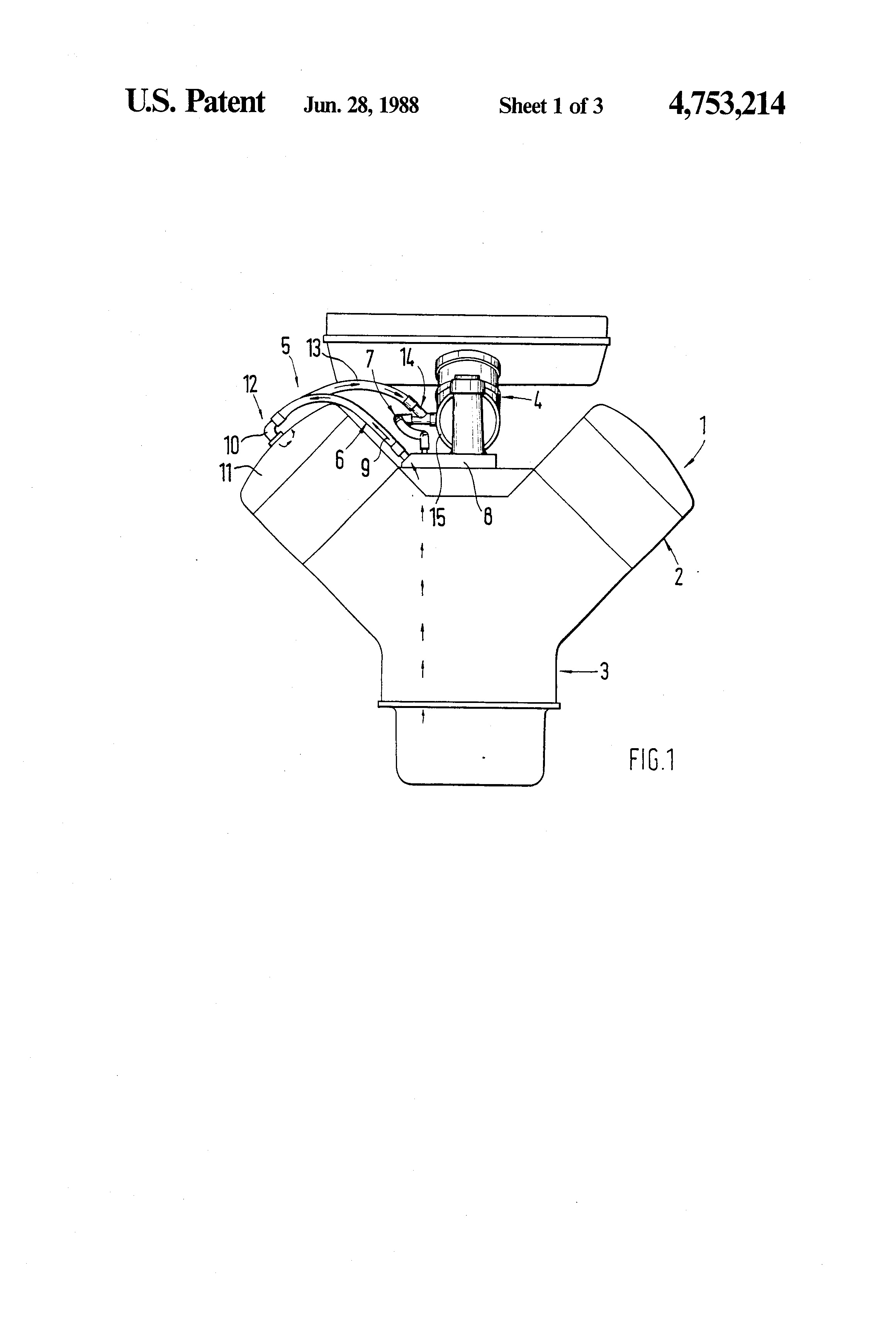
FIG. 2 is a diagrammatic view from above onto the crankcase ventilation system of FIG. 1;
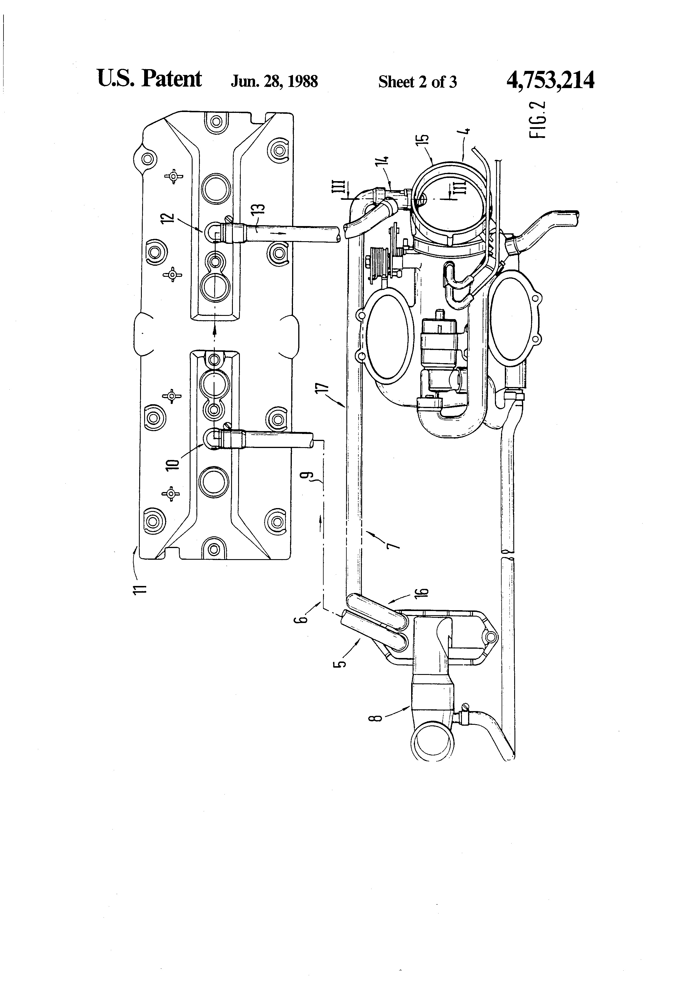
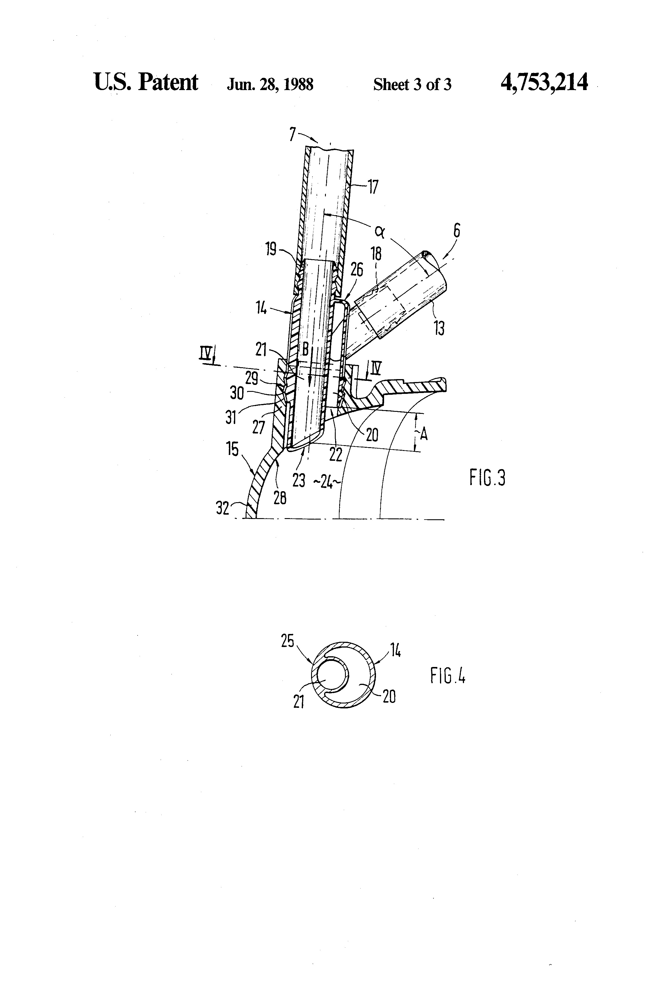
FIG. 3 is a sectional view taken along the Line III--III of FIG. 2; and
FIG. 4 is a sectional view taken along the Line IV--IV of FIG. 3.
DETAILED DESCRIPTION OF THE DRAWINGS
A multicylinder internal-combustion engine 1 for a motor vehicle comprises a cylinder head 2 and a cylinder block and crankcase 3. For the return of the crankcase gases from the cylinder block and crankcase 3 into an intake system 4 of the internal-combustion engine 1, a crankcase ventilation system is provided that is composed of a main ventilation system 6 and a safety ventilation system 7.
In the case of the main ventilation system 6, the crankcase gases (blow-by gases) move from the cylinder block and crankcase 3 into an oil filler neck 8. Subsequently, they pass through a line 9 that is connected via an angle connection 10 with a cylinder head cover 11 that penetrates it. Inside the cylinder head cover 11, between the two central cylinders, an oil separator is arranged that is not shown in detail. After flowing through the oil separator, the crankcase gases, via another angle connection 12 and a line 13 arranged outside the cylinder head cover, reach a connecting piece 14 that is arranged at an air guiding housing 15 of the intake system 4. Inside the angle connection 12, a throttle is inserted that is not shown.
When the main ventilation system 6 fails, for example, caused by icing (=closing of the throttle bore and/or of the outlet opening of the connecting piece), the excessive pressure in the cylinder block and crankcase 3 will rise because of lacking pressure balance and the safety ventilation system 7 will be actuated. In the case of the safety ventilation system 7, the crankcase gases, via an opening of the cylinder block and crankcase 3 that is not shown, will reach the oil filler neck 8. At 16, a safety valve is inserted into a connection of the oil filler neck 8 that opens at an excessive pressure of 80 to 100 mbar. When the safety valve is open, the crankcase gases, via a line 17, flow directly to the air guiding housing 15 (FIG. 2).
According to FIGS. 2 and 3, a joint connecting piece 14 having respective connecting pipe sections 18, 19 for the lines 13, 17 of the two systems 6, 7 (main ventilation system and safety ventilation system) is provided at the air guiding housing 15, in which case separate ducts 20, 21 lead away from the two connecting pipe sections 18, 19 and extend to remotely arranged outlet openings 22, 23. The two connecting pipe sections 18, 19 extend at an angle to one another. The outlet openings 22, 23 of the two ducts 20, 21, seen in flow direction B, extend at a distance A to one another and lead into the air guiding housing 15. Duct 21 of the safety ventilation system 7 that is shaped in a straight line extends as a continuation of the connecting pipe section 19 and with its free end containing the opening 23, in sections, projects into the interior space 24 of the air guiding housing 15. The cross-section of the duct 21, seen over its whole longitudinal course, is constant. The duct 20 of the main ventilation system 6 surrounds the duct 21 of the safety ventilation system 7 in sections, in which case the two ducts 20, 21 are arranged eccentrically with respect to one another. Wall sections of the interior duct 21 and of the exterior duct 20 are merged together at 25. The exterior duct 20 has an approximately crescent-shaped cross-section (FIG. 4).
The connecting pipe section 18 of the main ventilation system 6 extends at an angle to the connecting duct 20, the side 26 of the duct 20 that is opposite the outlet opening 22 being developed to be closed. The outlet opening 22 of the main ventilation system 6, seen in flow direction B, is arranged in front of the outlet opening 23 of the safety ventilation system 7, in such a way that the outlet opening 22 of the main ventilation system 6 extends in the area of a connecting pipe section 27 of the air guiding housing 15. The outlet opening 23 of the safety ventilation system 7 extends approximately in parallel to an interior limiting wall 28 of the air guiding housing 15.
The approximately Y-shaped connecting piece 14 is inserted into the molded-on connecting pipe section 27 of the air guiding housing 15 and connected with it via a locking connection 29. The locking connection 29 comprises groove-shaped molded-on parts 30 at the connecting piece 14 that engage in corresponding recesses 31 of the connecting pipe section 27. The air guiding housing 15 is formed by an air guiding scoop 32 developed in the shape of a pipe section connection that is arranged between an air mass meter and a throttle valve connection piece, namely below a throttle valve that is not shown.
Although the present invention has been described and illustrated in detail, it is to be clearly understood that the same is by way of illustration and example only, and is not to be taken by way of limitation. The spirit and scope of the present invention are to be limited only by the terms of the appended claims.
PATENT CITATIONS
Cited Patent Filing date Publication date Applicant Title
US2311036 * 27 May 1940 16 Feb 1943 Dick Wills Engine breather and ventilating system
US3059628 * 13 Dec 1960 23 Oct 1962 William J Linn Gas and fume disposal system for internal combustion engines
US3372685 * 5 Dec 1966 12 Mar 1968 Ardell T. Bestland Excessive crankcase pressure warning system and relief valve
US4011846 * 24 Mar 1975 15 Mar 1977 Did-Mor Engineering And Manufacturing Co. Anti-pollution device
DE3627376A1 * 12 Aug 1986 18 Feb 1988 Unilever Nv Bundle of a plurality of individual packs, and method for its manufacture
* Cited by examiner
NON-PATENT CITATIONS
Reference
1 * Porsche, Information Service 1985, 928S USA, Jun. 1985, pp. 30 & 31.
* Cited by examiner
REFERENCED BY
Citing Patent Filing date Publication date Applicant Title
US5140968 * 14 Feb 1992 25 Aug 1992 Navistar International Transportation Corp. Closed loop breather system for engine crankcase
US8151777 29 Oct 2008 10 Apr 2012 Toyota Jidosha Kabushiki Kaisha Intake pipe structure of internal combustion engine
CN1298968C * 15 Apr 2004 7 Feb 2007 日产自动车株式会社 Internal-combustion engine with cylinder mixing air recycle system
CN101230792B 22 Jan 2008 29 Dec 2010 通用汽车环球科技运作公司 Engine PCV system with venturi nozzle for flow regulation
CN101539044B 18 Mar 2009 30 Nov 2011 丰田自动车株式会社 用于内燃发动机的电控窜缸混合气返回装置
EP0874141A1 * 9 Apr 1998 28 Oct 1998 Daimler-Benz Aktiengesellschaft Venting device for the pipe connected to the intake manifold of a combustion engine
EP1469171A2 * 14 Apr 2004 20 Oct 2004 Nissan Motor Company, Limited Internal combustion engine with blow-by gas recirculation system
WO2009084144A1 * 29 Oct 2008 9 Jul 2009 Toyota Motor Co Ltd Intake pipe structure of internal combustion engine
* Cited by examiner
CLASSIFICATIONS
U.S. Classification 123/572
International Classification F02F7/00, F01M13/00, F02B75/22, F01M13/02
Cooperative Classification F02F7/006, F01M13/00, F02B75/22, F01M13/025
European Classification F01M13/00
LEGAL EVENTS
Date Code Event Description
10 Sep 1996 FP Expired due to failure to pay maintenance fee
Effective date: 19960703
30 Jun 1996 LAPS Lapse for failure to pay maintenance fees
6 Feb 1996 REMI Maintenance fee reminder mailed
30 Sep 1991 FPAY Fee payment
Year of fee payment: 4
12 Jun 1987 AS Assignment
Owner name: DR. ING. H.C.F. PORSCHE AKTIENGESELLSCHAFT, PORSCH
Free format text: ASSIGNMENT OF ASSIGNORS INTEREST.;ASSIGNORS:LANGLOIS, KARL;BATZILL, MANFRED;REEL/FRAME:004725/0879
Effective date: 19870604
US 4753214 A
ABSTRACT
A crankcase ventilation system for motor vehicles comprises a main ventilation system and a safety ventilation system, in which at an air guiding housing of the intake system, connecting pieces are arranged to which the lines of the two systems are connected. So that the connection between the lines of the two systems and the air guiding housing is simplified with respect to construction and also requires little space, a joint connecting piece having connecting pipe sections for the lines of both systems is provided at the air guiding housing. Separate ducts lead away from the connecting pipe sections and extend to remotely arranged outlet openings. The outlet openings of both ducts--seen in flow direction--extend at a distance from one another.
CLAIMS(15)
What is claimed:
1. A crankcase ventilation system for motor vehicles, in which the crankcase gases are returned from the cylinder block and crankcase into an air guiding housing of an intake system of an internal-combustion engine via a main ventilation system or a safety ventilation system for accommodating blockage of the main ventilation system, comprising
a main intake line connected to the main ventilation system and the crankcase,
a safety intake line connected to the safety ventilation system and the crankcase in by passing relation to the main intake line, and
a common connecting piece for connecting the air guiding housing with both the main intake line and the safety intake line.
2. A crankcase ventilation system according to claim 1, wherein said common connecting piece includes respective separate ducts which lead away from connecting pipe sections for the main intake line and the safety intake line, said separate ducts extending to remotely arranged outlet openings, and wherein outlet openings of the ducts, seen in flow direction, extend at a distance to one another and lead into the air guiding housing.
3. A crankcase ventilation system according to claim 2, wherein the connecting piece is developed to be approximately Y-shaped.
4. A crankcase ventilation system according to claim 2, wherein a duct of the safety ventilation system extends as a continuation of a pertaining connecting pipe section and has a straight shape.
5. A crankcase ventilation system according to claim 2, wherein a duct of the main ventilation system surrounds a duct of the safety ventilation system.
6. A crankcase ventilation system according to claim 5, wherein the two ducts of the main ventilation system and the safety ventilation system are arranged eccentrically with respect to one another.
7. A crankcase ventilation system according to claim 5, wherein wall sections of the ducts of the main ventilation system and the safety ventilation system rest against one another along portions thereof.
8. A crankcase ventilation system according to claim 2, wherein a outlet opening of the main ventilation system, seen in flow direction, is arranged in front of an outlet opening of the safety ventilation system.
9. A crankcase ventilation system according to claim 1, wherein a duct of the main ventilation system and an assigned connecting pipe section are placed against one another at an angle.
10. A crankcase ventilation system according to claim 2, wherein a duct of the main ventilation system is developed to be closed at the side that is opposite its outlet opening.
11. A crankcase ventilation system according to claim 2, wherein the connecting piece is inserted into a pipe section of the air guiding housing and is connected with it via a locking connection.
12. A crankcase ventilation system according to claim 2, wherein a duct of the safety ventilation system, with its free end containing an outlet opening, projects with portions thereof into the interior of the air guiding housing.
13. A crankcase ventilation system according to claim 2, wherein an end of the duct containing an outlet opening is arranged outside an interior limiting wall in the area of the pipe section.
14. A crankcase ventilation system according to claim 2, wherein the air guiding housing is formed by an air guiding scoop arranged between an air mass meter and a throttle valve pipe section.
15. A crankcase ventilation system according to claim 1, wherein said common connecting piece is a unitary one-piece molded part that includes respective main intake and safety intake ducts connecting the main intake line and the safety intake line to different outlet openings in the air guiding housing.
DESCRIPTION
BACKGROUND AND SUMMARY OF THE INVENTION
The invention relates to a crankcase ventilation system for motor vehicles, in which the crankcase gases are returned from the cylinder block and crankcase into an intake system of an internal-combustion engine via a main ventilation system or a safety ventilation system. Connecting pieces are arranged at an air guiding housing of the intake system for connecting lines of the main ventilation system and of the safety ventilation system.
In the case of a known crankcase ventilation system (Service Information 1985, Porsche 928 S, USA, Pages 30 and 31) of the initially mentioned type, two connecting pieces arranged at a spacing from one another are provided at the air guiding housing of the intake system, one connecting piece being connected with the line of the main ventilation system and the other connecting piece being connected with the line of the safety ventilation system. This crankcase ventilation system functions well, but the construction of the air guiding housing with the two connecting pieces is costly. In addition, the two connecting pieces require considerable space at the air guiding housing so that the narrow space conditions that anyhow are present particularly in the area of the intake system of a four-valve engine are limited even more.
It is an objective of the invention to take such measures at a crankcase ventilation system that the connection between the lines of the two systems and the air guiding housing is simplified with respect to construction and also requires little space.
According to the invention, this objective is achieved by providing a common connecting piece that connects both crankcase ventilation systems with the air guide housing. In certain preferred embodiments, the common connecting piece has outlet openings to the air guide housing that are spaced from one another in the vented gas flow direction. The preferred embodiments of the invention have a unitary connecting piece with a Y-shape, the arms of the y connecting respectively to the two ventilation systems.
The main advantages achieved by means of the invention are that by the arrangement of only one connecting piece for the lines of both systems, a simple and space-saving connection is established between the lines and the air guiding housing. By means of the separate ducts inside the connecting piece for the two systems and the outlet openings that are offset with respect to one another, a good functioning of the crankcase ventilation system is achieved. When the outlet opening of the main ventilation system is, for example, closed by ice, the safety ventilation system with the outlet opening that in sections projects into the inside of the air guiding housing will take over the crankcase ventilation until the closed connection of the main ventilation system in the air guiding housing has become penetrable again after the engine operating temperature or a sufficient engine compartment temperature has been reached. The connecting piece can be constructed in an easy and cost-effective way. Because of the locking connection between the connecting piece and the short pipe section of the air guiding housing in certain preferred embodiments, a rapid and easy mounting of the connecting piece is ensured.
Other objects, advantages and novel features of the present invention will become apparent from the following detailed description of the invention when considered in conjunction with the accompanying drawings.
BRIEF DESCRIPTION OF THE DRAWINGS
FIG. 1 is a frontal schematic view of an internal-combustion engine having a crankcase ventilation system constructed in accordance with a preferred embodiment of the invention;
FIG. 2 is a diagrammatic view from above onto the crankcase ventilation system of FIG. 1;
FIG. 3 is a sectional view taken along the Line III--III of FIG. 2; and
FIG. 4 is a sectional view taken along the Line IV--IV of FIG. 3.
DETAILED DESCRIPTION OF THE DRAWINGS
A multicylinder internal-combustion engine 1 for a motor vehicle comprises a cylinder head 2 and a cylinder block and crankcase 3. For the return of the crankcase gases from the cylinder block and crankcase 3 into an intake system 4 of the internal-combustion engine 1, a crankcase ventilation system is provided that is composed of a main ventilation system 6 and a safety ventilation system 7.
In the case of the main ventilation system 6, the crankcase gases (blow-by gases) move from the cylinder block and crankcase 3 into an oil filler neck 8. Subsequently, they pass through a line 9 that is connected via an angle connection 10 with a cylinder head cover 11 that penetrates it. Inside the cylinder head cover 11, between the two central cylinders, an oil separator is arranged that is not shown in detail. After flowing through the oil separator, the crankcase gases, via another angle connection 12 and a line 13 arranged outside the cylinder head cover, reach a connecting piece 14 that is arranged at an air guiding housing 15 of the intake system 4. Inside the angle connection 12, a throttle is inserted that is not shown.
When the main ventilation system 6 fails, for example, caused by icing (=closing of the throttle bore and/or of the outlet opening of the connecting piece), the excessive pressure in the cylinder block and crankcase 3 will rise because of lacking pressure balance and the safety ventilation system 7 will be actuated. In the case of the safety ventilation system 7, the crankcase gases, via an opening of the cylinder block and crankcase 3 that is not shown, will reach the oil filler neck 8. At 16, a safety valve is inserted into a connection of the oil filler neck 8 that opens at an excessive pressure of 80 to 100 mbar. When the safety valve is open, the crankcase gases, via a line 17, flow directly to the air guiding housing 15 (FIG. 2).
According to FIGS. 2 and 3, a joint connecting piece 14 having respective connecting pipe sections 18, 19 for the lines 13, 17 of the two systems 6, 7 (main ventilation system and safety ventilation system) is provided at the air guiding housing 15, in which case separate ducts 20, 21 lead away from the two connecting pipe sections 18, 19 and extend to remotely arranged outlet openings 22, 23. The two connecting pipe sections 18, 19 extend at an angle to one another. The outlet openings 22, 23 of the two ducts 20, 21, seen in flow direction B, extend at a distance A to one another and lead into the air guiding housing 15. Duct 21 of the safety ventilation system 7 that is shaped in a straight line extends as a continuation of the connecting pipe section 19 and with its free end containing the opening 23, in sections, projects into the interior space 24 of the air guiding housing 15. The cross-section of the duct 21, seen over its whole longitudinal course, is constant. The duct 20 of the main ventilation system 6 surrounds the duct 21 of the safety ventilation system 7 in sections, in which case the two ducts 20, 21 are arranged eccentrically with respect to one another. Wall sections of the interior duct 21 and of the exterior duct 20 are merged together at 25. The exterior duct 20 has an approximately crescent-shaped cross-section (FIG. 4).
The connecting pipe section 18 of the main ventilation system 6 extends at an angle to the connecting duct 20, the side 26 of the duct 20 that is opposite the outlet opening 22 being developed to be closed. The outlet opening 22 of the main ventilation system 6, seen in flow direction B, is arranged in front of the outlet opening 23 of the safety ventilation system 7, in such a way that the outlet opening 22 of the main ventilation system 6 extends in the area of a connecting pipe section 27 of the air guiding housing 15. The outlet opening 23 of the safety ventilation system 7 extends approximately in parallel to an interior limiting wall 28 of the air guiding housing 15.
The approximately Y-shaped connecting piece 14 is inserted into the molded-on connecting pipe section 27 of the air guiding housing 15 and connected with it via a locking connection 29. The locking connection 29 comprises groove-shaped molded-on parts 30 at the connecting piece 14 that engage in corresponding recesses 31 of the connecting pipe section 27. The air guiding housing 15 is formed by an air guiding scoop 32 developed in the shape of a pipe section connection that is arranged between an air mass meter and a throttle valve connection piece, namely below a throttle valve that is not shown.
Although the present invention has been described and illustrated in detail, it is to be clearly understood that the same is by way of illustration and example only, and is not to be taken by way of limitation. The spirit and scope of the present invention are to be limited only by the terms of the appended claims.
PATENT CITATIONS
Cited Patent Filing date Publication date Applicant Title
US2311036 * 27 May 1940 16 Feb 1943 Dick Wills Engine breather and ventilating system
US3059628 * 13 Dec 1960 23 Oct 1962 William J Linn Gas and fume disposal system for internal combustion engines
US3372685 * 5 Dec 1966 12 Mar 1968 Ardell T. Bestland Excessive crankcase pressure warning system and relief valve
US4011846 * 24 Mar 1975 15 Mar 1977 Did-Mor Engineering And Manufacturing Co. Anti-pollution device
DE3627376A1 * 12 Aug 1986 18 Feb 1988 Unilever Nv Bundle of a plurality of individual packs, and method for its manufacture
* Cited by examiner
NON-PATENT CITATIONS
Reference
1 * Porsche, Information Service 1985, 928S USA, Jun. 1985, pp. 30 & 31.
* Cited by examiner
REFERENCED BY
Citing Patent Filing date Publication date Applicant Title
US5140968 * 14 Feb 1992 25 Aug 1992 Navistar International Transportation Corp. Closed loop breather system for engine crankcase
US8151777 29 Oct 2008 10 Apr 2012 Toyota Jidosha Kabushiki Kaisha Intake pipe structure of internal combustion engine
CN1298968C * 15 Apr 2004 7 Feb 2007 日产自动车株式会社 Internal-combustion engine with cylinder mixing air recycle system
CN101230792B 22 Jan 2008 29 Dec 2010 通用汽车环球科技运作公司 Engine PCV system with venturi nozzle for flow regulation
CN101539044B 18 Mar 2009 30 Nov 2011 丰田自动车株式会社 用于内燃发动机的电控窜缸混合气返回装置
EP0874141A1 * 9 Apr 1998 28 Oct 1998 Daimler-Benz Aktiengesellschaft Venting device for the pipe connected to the intake manifold of a combustion engine
EP1469171A2 * 14 Apr 2004 20 Oct 2004 Nissan Motor Company, Limited Internal combustion engine with blow-by gas recirculation system
WO2009084144A1 * 29 Oct 2008 9 Jul 2009 Toyota Motor Co Ltd Intake pipe structure of internal combustion engine
* Cited by examiner
CLASSIFICATIONS
U.S. Classification 123/572
International Classification F02F7/00, F01M13/00, F02B75/22, F01M13/02
Cooperative Classification F02F7/006, F01M13/00, F02B75/22, F01M13/025
European Classification F01M13/00
LEGAL EVENTS
Date Code Event Description
10 Sep 1996 FP Expired due to failure to pay maintenance fee
Effective date: 19960703
30 Jun 1996 LAPS Lapse for failure to pay maintenance fees
6 Feb 1996 REMI Maintenance fee reminder mailed
30 Sep 1991 FPAY Fee payment
Year of fee payment: 4
12 Jun 1987 AS Assignment
Owner name: DR. ING. H.C.F. PORSCHE AKTIENGESELLSCHAFT, PORSCH
Free format text: ASSIGNMENT OF ASSIGNORS INTEREST.;ASSIGNORS:LANGLOIS, KARL;BATZILL, MANFRED;REEL/FRAME:004725/0879
Effective date: 19870604
04-04-2014, 11:50 PM
#102
Nordschleife Master
Thread Starter
Reading the patent is illuminating. What they described in the patent was implemented in the '87 S4.
The factory intent was to primarily vent from the filler neck to the valve cover and then from the valve cover to the MAF elbow. For this to work, they must have assumed that the oil filler neck always has a higher pressure than the valve cover. We should verify that assumption. If the assumption is not true, then there is trouble with the air flowing the wrong way in oil drain channels.
The connection from the oil filler neck to the MAF elbow Y was thought of as a secondary, backup, "safety" venting channel. For that to work, all that was needed the static pressure at the MAF elbow being lower than at oil filler neck. It is not necessary for the valve covers to have a lower pressure than the oil filler neck.
Inexplicably, in the GTS model they eliminated the path that was described as the main breather channel in the patent. They connected the passenger valve cover to the driver valve cover. I can only think of one logical explanation of why they did this. They intended the crankcase to vent to the valve covers thru the head oil drains. The two valve covers were connected, because under lateral g-forces one side of oil drains, but not both, could be blocked by oil. They counted on at least some of the eight large oil drains to flow enough blowby gas to the valve covers that they could then be routed to the passenger side and then to the MAF elbow. The safety vent directly from the oil filler neck to the MAF elbow remains there.
What could have motivated the change? The components aren't any cheaper in the GTS version, in fact there's one more metal valve cover elbow fitting needed which is expensive. They must have thought that the connection that they eliminated, from the oil filler neck to the passenger side valve cover was counterproductive. The only way that I can think of it being counterproductive is if they came to the conclusion that air was flowing in the wrong direction from the front of the passenger side valve cover to the oil filler neck and that air being replaced by air flowing up the drain channel. Why else would they eliminated that connection?
This leads to the interesting question why would air flow from the valve cover to the oil filler neck? The only reasons I can come up with are the following: either it's the piston pumping pulses doing something unexpected, or the crankshaft rotation pulling a low pressure to the oil filler neck at high rpms.
Anyone else with any hypotheses why they moved away from the scheme of the patent?
Also, what's up with the check valve in the y? Here's Mike Schmidt writing about the system: https://rennlist.com/forums/attachme...perform-it.doc
Mike mentions that there' a check valve in the y-piece. The patent doesn't mention it and neither of the two y-pieces I have have a check valve. Unless the check valve is the 100 millibar valve they mention. That's it I am guessing. 100 millibars is a lot, though, like 1.5 psi. It really is only a safety valve then if calibrated as the patent prescribes, and the filler neck to will only vent directly to the filler neck when the situation is pretty dire in terms of excessive crankcase pressure.
Edit: mystery solved, my spare 87 engine has a check valve in the oil filler neck. Haven't measured the cracking pressure, though.
Ok, so the mystery deepens. The factory seems to have eliminated the check valve from the GTS oil filler neck when they moved the port higher. Is this true? If it is true then, isn't the throttle closed breather flush function simply going to draw the air from MAF elbow and the crankcase doesn't get flushed with fresh air? I think I understand the factory's intent with the S4 breather system, but now the GTS system doesn't look very well though out to me. Maybe they thought that by connecting the valve covers they would get enough crank rotation induced flow in the heads and crankcase, and wanted to eliminate the check valve simply to increase the flow capacity of the system?
The factory intent was to primarily vent from the filler neck to the valve cover and then from the valve cover to the MAF elbow. For this to work, they must have assumed that the oil filler neck always has a higher pressure than the valve cover. We should verify that assumption. If the assumption is not true, then there is trouble with the air flowing the wrong way in oil drain channels.
The connection from the oil filler neck to the MAF elbow Y was thought of as a secondary, backup, "safety" venting channel. For that to work, all that was needed the static pressure at the MAF elbow being lower than at oil filler neck. It is not necessary for the valve covers to have a lower pressure than the oil filler neck.
Inexplicably, in the GTS model they eliminated the path that was described as the main breather channel in the patent. They connected the passenger valve cover to the driver valve cover. I can only think of one logical explanation of why they did this. They intended the crankcase to vent to the valve covers thru the head oil drains. The two valve covers were connected, because under lateral g-forces one side of oil drains, but not both, could be blocked by oil. They counted on at least some of the eight large oil drains to flow enough blowby gas to the valve covers that they could then be routed to the passenger side and then to the MAF elbow. The safety vent directly from the oil filler neck to the MAF elbow remains there.
What could have motivated the change? The components aren't any cheaper in the GTS version, in fact there's one more metal valve cover elbow fitting needed which is expensive. They must have thought that the connection that they eliminated, from the oil filler neck to the passenger side valve cover was counterproductive. The only way that I can think of it being counterproductive is if they came to the conclusion that air was flowing in the wrong direction from the front of the passenger side valve cover to the oil filler neck and that air being replaced by air flowing up the drain channel. Why else would they eliminated that connection?
This leads to the interesting question why would air flow from the valve cover to the oil filler neck? The only reasons I can come up with are the following: either it's the piston pumping pulses doing something unexpected, or the crankshaft rotation pulling a low pressure to the oil filler neck at high rpms.
Anyone else with any hypotheses why they moved away from the scheme of the patent?
Also, what's up with the check valve in the y? Here's Mike Schmidt writing about the system: https://rennlist.com/forums/attachme...perform-it.doc
The air can't go through the smaller diameter angle cut section of the plastic "Y" piece because of the check valve.
Edit: mystery solved, my spare 87 engine has a check valve in the oil filler neck. Haven't measured the cracking pressure, though.
Ok, so the mystery deepens. The factory seems to have eliminated the check valve from the GTS oil filler neck when they moved the port higher. Is this true? If it is true then, isn't the throttle closed breather flush function simply going to draw the air from MAF elbow and the crankcase doesn't get flushed with fresh air? I think I understand the factory's intent with the S4 breather system, but now the GTS system doesn't look very well though out to me. Maybe they thought that by connecting the valve covers they would get enough crank rotation induced flow in the heads and crankcase, and wanted to eliminate the check valve simply to increase the flow capacity of the system?
Last edited by ptuomov; 04-05-2014 at 02:51 PM. Reason: Heavily edited because of errors and new info
04-05-2014, 02:51 PM
#103
Electron Wrangler
Lifetime Rennlist
Member
Lifetime Rennlist
Member
There is no check valve on a ('94) GTS either in the Y (and I don't see how a decent one could realistically fit) or in the filler neck (on a GTS all connections are at the top and easily visible).
I think the patent describes a lot about configuration (for protection), but ultimately very little about their expectation of how it works - beyond an over basic primary & safety (some trade secrets retained?). Their explanation of the need for a safety system (icing of the orifice) seems very weak indeed... a safety is needed to cope with cases of excess blowby - period. The sizing of the primary lines here and the orifices make that a highly likely case...
I think the changes on the GTS indicate they had concluded that more blowby makes it to the passenger head via the drains Vs. via the piddly little vent tube - why wouldn't it - looking at the wide open areas involved. Maybe just on the GTS they realized this got a lot worse so made changes to compensate. But I suspect it means their evac system didn't really work that well after all - but maybe ~just about good enough for the S4 engines.
Maybe just so little flowed in that primary vent line (but I'd guess not reversed...) that they considered it would be better to use it to open a secondary relief path up the drivers drains as you say. Either way I'd say it was really too small for this purpose - might have been better to evacuate from both rear cam vents to the Y
There is an interesting section:
"Inside the cylinder head cover 11, between the two central cylinders, an oil separator is arranged that is not shown in detail."
What is this? - if it ever existed in that location - the rear oil drains would presumably bypass it anyway...?
This thing seems to be full of holes... (even literally)
Alan
Last edited by Alan; 04-06-2014 at 06:48 PM.
04-05-2014, 04:01 PM
#104
Nordschleife Master
Thread Starter
If there is no check valve in the oil filler neck, like with the GTS, what's to prevent the closed throttle circuit from drawing the air directly from the hose that connects the oil filler neck and the MAF elbow? As far as I see nothing. If so, there's not fresh air circulating in the crankcase, removing water and fuel vapors.
The early GTS, based on hearsay, has a 6mm restrictor in the valve cover elbow and a 5mm restrictor in the oil filler neck. That arrangement flows about the same as the S4 system at high crankcase pressures, assuming that the 5mm orifice and the safety check valve flow about the same.
According to hearsay, some GTS engines have no 6mm restrictor in the valve cover elbow. This will increase the flow capacity of the system, but now the gas velocity in the air-oil separator tube in the valve cover may become too high and the elbow will spew out oil. It would in my opinion be a preferable solution to increasing flow capacity to add an additional breather to the other side and retain the 6 mm restrictor on both sides.
If one drills out those elbows to vent out gas, then in my opinion one has to have another air-oil separator downstream.
Thete is no check valve on a GTS either in the Y (and I don't see how a decent one could realistically fit) or in the filler neck (on a GTS all connections are at the top and easily visible).
I think the patent describes a lot about configuration (for protection), but ultimately very little about their expectation of how it works - beyond an over basic primary & safety (some trade secrets retained?). Their explanation of the need for a safety system (icing of the orifice) seems very weak indeed... a safety is needed to cope with cases of excess blowby - period. The sizing of the primary lines here and the orifices make that a highly likely case...
I think the changes on the GTS indicate they had concluded that more blowby makes it to the passenger head via the drains Vs. via the piddly little vent tube - why wouldn't it - looking at the wide open areas involved. Maybe just on the GTS they realized this got a lot worse so made changes to compensate. But I suspect it means their evac system didn't really work that well after all - but maybe ~just about good enough for the S4 engines.
Maybe just so little flowed in that primary vent line (but I'd guess not reversed...) that they considered it would be better to use it to open a secondary relief path up the drivers drains as you say. Either way I'd say it was really too small for this purpose - might have been better to evacuate from both rear cam vents to the Y
There is an interesting section:
"Inside the cylinder head cover 11, between the two central cylinders, an oil separator is arranged that is not shown in detail."
What is this? - if it ever existed in that location - the rear oil drains would presumably bypass it anyway...?
This thing seems to be full of holes... (even literally)
Alan
04-05-2014, 06:12 PM
#105
Electron Wrangler
Lifetime Rennlist
Member
Lifetime Rennlist
Member
I concluded that a bigger evacuation vents and a better separation method was needed too...
I'd like to know if there ever was any kind of separator in the cam cover - apart from the fact that the spare volume is low - it would have been a good place to construct a wide & shallow labarinth /drainback type separator before the elbow - the breather shroud added on the GTS is actually pretty pathetic - simply what could fit easily & cheaply after the fact - a poor end of life band aid type effort.
I have a Y in my hand now - size wise it looks just like the patent diagram (I see no part number but PET says 928.110.690.01 for all GTS cars AND for all 1987-1991 too), there is no check valve both go straight through - to me there simply isn't room for a decent flow check valve integrated here - to those that say they exist please just show one? Below a picture of the GTS throttle body Y, with an LED light shining into the off-axis port - just wide open.
If there is a check valve it isn't integrated in the Y.
That there is only a restrictor (orifice) in the GTS filler neck is also pretty definitive (picture of stock GTS filler neck 928.107.303.09 PET says same for all GTS cars).
Alan
Last edited by Alan; 04-05-2014 at 06:49 PM.