When you click on links to various merchants on this site and make a purchase, this can result in this site earning a commission. Affiliate programs and affiliations include, but are not limited to, the eBay Partner Network.
Tuomo you have implied several times that you think the heads may be at a higher effective static pressure than the main crank - true? if so why? You also seem to imply that the dynamic pulses may be large in the heads - why? - due to interbay differences equalizing through the oil drains? other?
First of all, I don't know this for sure but it's one of the first things I'll test once I get on with this program. Everything below is speculation.
I think that the baffle design inside the block chimney has consequences that are unknown to most in terms of pressure that exists in the oil filler neck. The bay 1 sees relatively violent pressure pulses from the piston pumping action. In addition, the rotating crankshafts creates some pressure. The crankshaft rotation pressure is much smaller than the piston pumping pressure, but it's more consistent.
At 315 degrees, the crankshaft crank pin is pointing towards the the passenger side cylinder bank and the piston in the driver side cylinder is moving up at near its maximum velocity. This creates a massive suction pulse that will draw a big vacuum to the oil filler neck for an instant. If the conditions are such that this pulse can draw gas from either the intake tract or (worse) from the heads. The rotating crankshaft will also draw some (relative modest) vacuum at that location.
If you stare at the simulated flow fields from a similar V8 engine, it becomes pretty clear that it will be difficult to design a baffle that will get a high pressure and only little oil from the chimney.
If one goes with a design that produces a relatively low pressure and low oil, then one is better off not venting from the valve covers and not connecting the valve covers to the chimney. If one instead goes with a baffle design that produces a lot of oil but a relatively high pressure, then one might be able to connect the heads with the block chimney and to vent from the valve covers.
One more note to add. Almost all separators need a pressure differential between inlet and outlet to separate oil and air. (Pure volume based gravity separators are an exception, but those are too large for the 928 engine bay.). An impactor needs a pressure differential to accelerate the mixture. Cyclone needs it to force the oil to the wall. Coalescing filter needs it to push the mixture thru the filter element. Effective air oil separation is going to need a pressure differential of some kind, whether that comes from vacuum pump, intake manifold, Venturi jet pump, or whatever. So first thing to look for is an acceptable pressure differential somewhere in the system.
I've got some ideas of how to deal with this, but at this point they are just untested ideas.
before i left ohio last year i had a hell of an smoke screen forming on deceleration and a partial one on take off. thought the valves seals were junk or the rings took a shiz.... turns out it was my "hillbilly hot rod style" crank case evac set up. was not working causing the crankcase to pressurize and force oil in to the cylinder. so i added Colin's pump set up. at first the provent i had could not handle the discharge from the pump, but when i replaced it with this little air/oil separator.... much joy is not had. i have been happy with it.
Two new crankcase evacuation ideas for boosted cars. The first is for street cars and the second is for race cars.
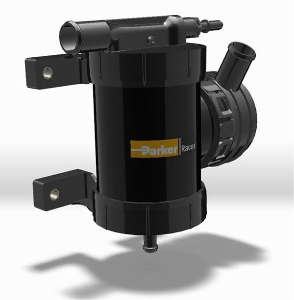
The first idea uses Parker-Racor Superimpactor. The idea in the super impactor is to use a small fraction of the boosted air to power an active air-oil separator. The best way to set this up is to pull crankcase gasses from baffled oil filler neck into the super impactor. The cleaned gasses from the super impactor will be routed to the compressor inlet. The compressed air powering the super impactor will be pulled from the intercooler bottom end tank. Finally, the separated oil will be drained back to the sump thru a check valve. A small fraction of the boosted air will be used to power the super impactor, and if a tiny bit of oil will collect into the intercooler, it will be sucked back into the super impactor as part of the drive pressure circuit flow.
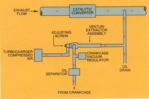
The second idea is to use the exhaust flow to evacuate the crankcase with an assist from boost. There is a slash cut tube in the exhaust downstream of the turbine (if any). There's a venturi vacuum jet pump that takes its drive pressure from the pressurized intake side and exits to the slash cut tube in the exhaust. The vacuum port of the venturi vacuum jet pump is connected to the crankcase, preferrably with a catch can or separator in between. The pressure side has an adjustment screw that will control the amount of boost leaked to the pump and thereby the vacuum generated at the vacuum port. The vacuum pulled by this method is powerful enough that a vacuum regulator may be needed.
We're about to lock down the design of the next iteration of the crankcase breather system for the turbo car. Any last minute comments, suggestions, or warnings?
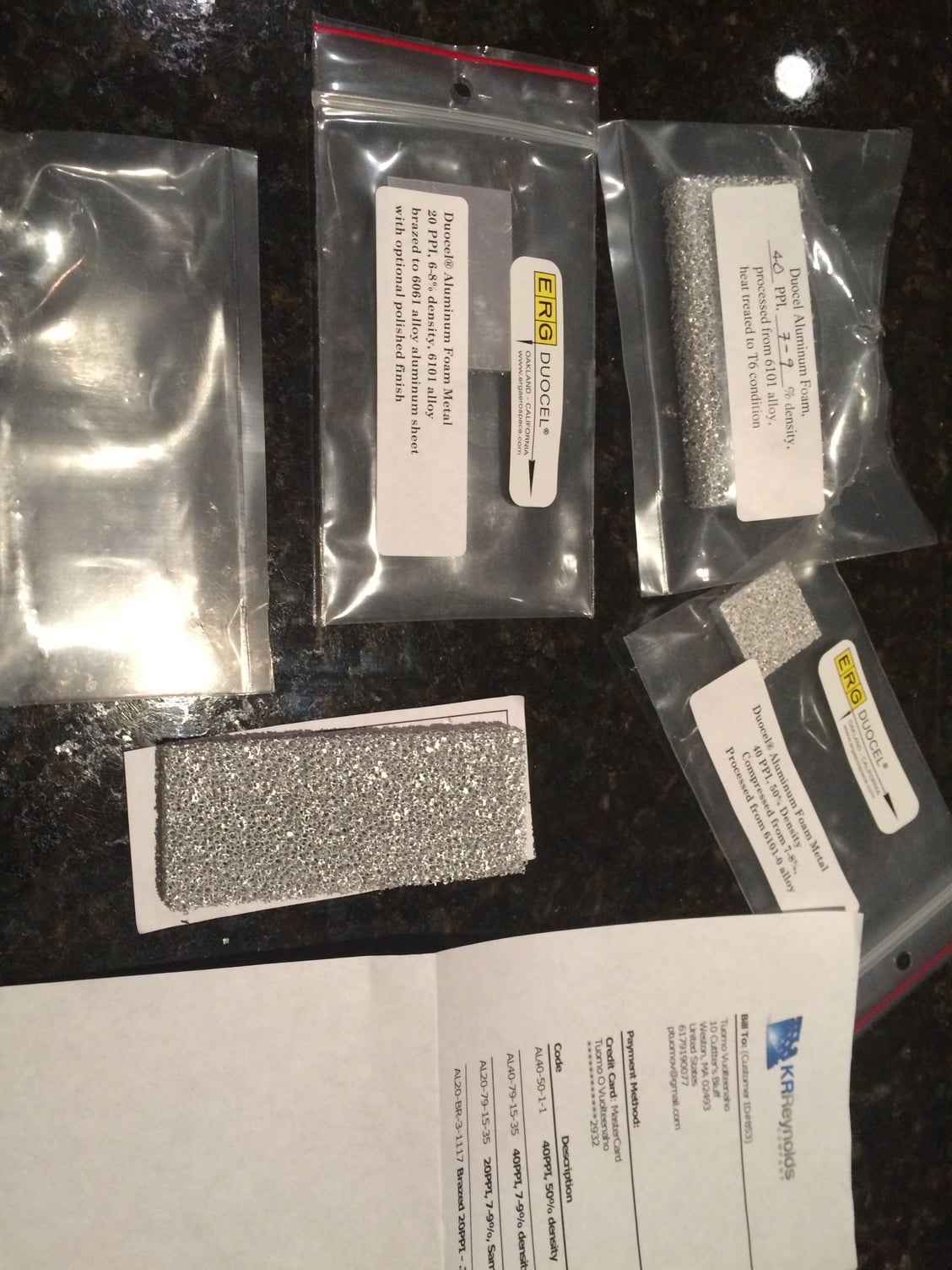
To those of you who like good separation with a reliable material and aren't prioritizing the gas flow rates, here's some interesting material:
That's duocel aluminum foam that is very durable. I have the test material and the gas flow rates as a function of area and pressure drop for different densities and cell counts. It'll work very well equalizing the flow velocities in a passage and removing larger oil droplets. It won't remove very fine droplets without centrifugal effect from a spinning disc, but those aren't the big problem for us looking to improve the pre-separator.
One person is running this configuration in his normally aspirated motor and it has helped with oil consumption, so there's some evidence for it working.
This summer, we'll get two turbo cars on the road with this breather system. We'll have the ability to both measure the blowby gas flow and the oil ejected from the system, so that'l give us some data.
One person is running this configuration in his normally aspirated motor and it has helped with oil consumption, so there's some evidence for it working.
Pleased to own up to being the guinea pig here!
I have had some oil issues with my motor ever since I purchased my late S4 in 1998. The previous owner told me "they all do that" and maybe they do but it has always intrigued me as to why some 928 S4's reportedly do not use any oil.
After my accident when I lost the S4 back in 2006[?] we partly stripped the motor to replace a couple of valves and took a close look at the bores which the main dealers felt to be perfect after a few trial measurements of the bore. Compression pressures were very even at 185 psig on my test rig and eventually I got round to doing a leakdown test and that was very positive.
After fitting my S4 motor into the GTS chassis I purchased I then made the huge mistake of trying to convert the motor to the GTS breather system setup using the filler neck from the TBF'd original GTS motor. Oil consumption then got worse so needed to do something. I could have reverted to the S4 system but I decided to go more radical. In this regard I decided to have a crack at something along the lines Louie suggested to me many years ago and purchased a Pro Vent. I also came across the baffle John Kuhn makes and placed one of those at the base of the filler chimney. I then made a 1 inch aperture in the underside of the filler neck and inserted a fitting John supplied together with a hose to take the flow from the filler neck to the Pro Vent. I also vented the cam covers into the Pro vent as well with the gas outlet open to atmosphere [not very green]. Oil consumption dropped a bit but was still way more than I was happy with.
I posted about my concerns and discussed the matter with a number of my 928 penfriends to try and work out what next. When Tuomo started posting on this matter I told him about my issues and what I had tried and then he graciously invited me to consider a trial of a system he was developing. I had most of the necessary elements in place but to achieve the design I needed to remove the inlet manifold [plumbing mods] and the driver side cam cover [to fit a 4th breather connection].
The tricky bit was making some plumbing to get the gases returned to the nozzle on the boot. I did this by splitting the gas outlet from the pro vent into two lines and running them to the stock connector on the boot. I used a mix of plumbing fitting and spare redundant hoses to make new plumbing. The end result was surprisingly tidy and not at all out of place, some of it well hidden in the vee.
Since I fitted the mod I have been plagued by a number of minor unrelated issues so not the best of guineau pigs- but have now completed some 2000 km and the oil level has seemingly not dropped. The Kuhn baffle appears to knock out most of the oil with very little [a few CC's] emanating from the pro vent and being caught in a sealed catch bottle.
Although more driving needs to be done to verify the performance of this system it certainly looks very promising indeed. Even at best conditions with the original S4 breather system and the engine driving softly it would typically consume a litre of oil over such distance and the worst I have seen is about a litre every 500km. Thus it seems quite a notable improvement has been realised.
The motor really needs a good long run before declaring victory but so far so good and I am convinced it works where my previous attempts failed.
Thanks for posting your experience, which is - if not conclusive - encouraging. We'll have two turbo cars with this system out this summer and we'll do a real stress test of this system.
The "aha" moment in the crankcase breather project was when I separated all operating modes and considered the engine oil flow and gas flow separately in each of the modes. The acceleration forces work against the stock system. Configuring the throttle closed mode to pull vapors from the rear of the engine and the WOT mode to pull vapors from the front of the engine makes the acceleration forces to work for the system in terms of separating air and oil.
Another thing that I consider important is that the in the WOT mode, the breather system must encourage gas flow from the heads to the oil pan, not the other way around. This is to improve the oil drain.
I think I also figured out what Porsche engineers were trying when they connected the valve covers to each other in their "failed" GTS design. It was to encourage oil drain in situations in which the drain channels are flooded in cornering and crankcase pressure would otherwise exceed the valve cover pressure. The purpose is roughly analogous to the inside breather channels in the modern 4-valve V8's.
In any case, the system is purely "open source" so anyone can test or use it. In my opinion, that's the only way to detect any weaknesses in my design - lay it all out on the open so it can be critiqued and tested.
Did you have any photos of how the plumbing worked out?
Originally Posted by FredR
Pleased to own up to being the guinea pig here!
I have had some oil issues with my motor ever since I purchased my late S4 in 1998. The previous owner told me "they all do that" and maybe they do but it has always intrigued me as to why some 928 S4's reportedly do not use any oil.
After my accident when I lost the S4 back in 2006[?] we partly stripped the motor to replace a couple of valves and took a close look at the bores which the main dealers felt to be perfect after a few trial measurements of the bore. Compression pressures were very even at 185 psig on my test rig and eventually I got round to doing a leakdown test and that was very positive.
After fitting my S4 motor into the GTS chassis I purchased I then made the huge mistake of trying to convert the motor to the GTS breather system setup using the filler neck from the TBF'd original GTS motor. Oil consumption then got worse so needed to do something. I could have reverted to the S4 system but I decided to go more radical. In this regard I decided to have a crack at something along the lines Louie suggested to me many years ago and purchased a Pro Vent. I also came across the baffle John Kuhn makes and placed one of those at the base of the filler chimney. I then made a 1 inch aperture in the underside of the filler neck and inserted a fitting John supplied together with a hose to take the flow from the filler neck to the Pro Vent. I also vented the cam covers into the Pro vent as well with the gas outlet open to atmosphere [not very green]. Oil consumption dropped a bit but was still way more than I was happy with.
I posted about my concerns and discussed the matter with a number of my 928 penfriends to try and work out what next. When Tuomo started posting on this matter I told him about my issues and what I had tried and then he graciously invited me to consider a trial of a system he was developing. I had most of the necessary elements in place but to achieve the design I needed to remove the inlet manifold [plumbing mods] and the driver side cam cover [to fit a 4th breather connection].
The tricky bit was making some plumbing to get the gases returned to the nozzle on the boot. I did this by splitting the gas outlet from the pro vent into two lines and running them to the stock connector on the boot. I used a mix of plumbing fitting and spare redundant hoses to make new plumbing. The end result was surprisingly tidy and not at all out of place, some of it well hidden in the vee.
Since I fitted the mod I have been plagued by a number of minor unrelated issues so not the best of guineau pigs- but have now completed some 2000 km and the oil level has seemingly not dropped. The Kuhn baffle appears to knock out most of the oil with very little [a few CC's] emanating from the pro vent and being caught in a sealed catch bottle.
Although more driving needs to be done to verify the performance of this system it certainly looks very promising indeed. Even at best conditions with the original S4 breather system and the engine driving softly it would typically consume a litre of oil over such distance and the worst I have seen is about a litre every 500km. Thus it seems quite a notable improvement has been realised.
The motor really needs a good long run before declaring victory but so far so good and I am convinced it works where my previous attempts failed.
Thanks for posting your experience, which is - if not conclusive - encouraging. We'll have two turbo cars with this system out this summer and we'll do a real stress test of this system.
Did you have any photos of how the plumbing worked out?
Tuomo,
Let me see what I can dig out photo wise- I did a couple of iterations on the gas return lines- a bit of a cut and paste job but the "untidy bits" are generally located in the vee so not really visible as it were. The only thing one really notices is the Pro vent unit and the crossover at the rear that is mostly hidden anyway.
I would like to take a trip up to Dubai [about a 1k km round trip] with opportunity to test the system a bit more robustly on the way back [if I can sort the other immediate issues out]- this motor always felt much better after a good run up there and back to blow the cobwebs out. Just have to take it steady on the way up given the state [old age] of the rear tyre that is starting to show signs of cracking on the tread blocks. Even so modern technology has caught up with us with fixed radar and hidden mobile units not to mention much more heavy traffic. Gone are the days when I could use warp drive but some good roads nonetheless!
Had the car out for a short run this afternoon and I am convinced it is also running crisper [placebo?]. I am wondering if it really has reduced the amount of oil in the combustion chamber as I suspect it has whether I can dial in a bit more advance in ST2. I found I had to run a bit less advance at full load than the stock maps but that could be down to having a fast exhaust or too much oil inducing detonation events. Either way figured I would test the system for 5k km or so before going further down that path.
It would be good to see some other analogues to compare performance.
As promised as few pics of the installation- a bit of a pot pourri of bits and pieces in my spares kit. Hopefully I can improve on this if it proves as positive as it seems at the moment.
My home brew catch bottle [sealed] only has a few cc's of oil in it. Eventually I would hope to return this directly via the dip stick tube if I can get my spare dip stick tube modified.
What I consider to be the essential elements of the system are there in your car, namely well-designed baffle in the chimney, venting from the back of the engine during deceleration, venting from the front of the engine during acceleration, connecting the valve covers of the two banks to aid oil drain during cornering, and not connecting the oil filler neck directly to the valve covers as that might create counter-productive gas circulation in the oil drains.
There's one modification to your system that might eliminate the last drops of oil from the ProVent. Currently, your oil-filler neck breather port is at the front-bottom of the filler neck. (Mine was in the same spot in the previous version.) We're moving that to the side in this new version. The reason why we're moving it to the side is that during deceleration, a small amount of oil that's in the filler neck gets thrown to the front of the neck and possible from there to the vent hose if the vent hose is connected to the front bottom. The new version will vent from the sides of the oil filler neck, a little further back than the oil filler cap. (http://cimg7.ibsrv.net/gimg/rennlist...b56f21e53.jpeg)

 03-15-2015, 11:08 AM