
S4 intake manifold facts and ideas
 02-01-2015, 07:39 PM
#181
Nordschleife Master
Thread Starter
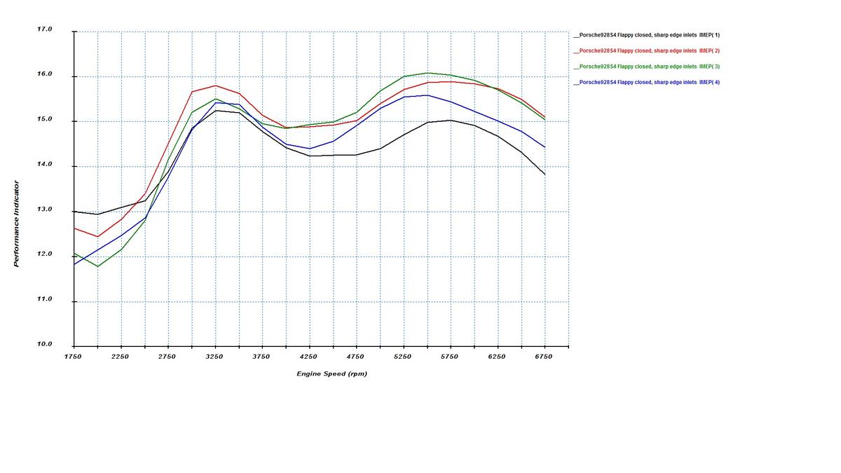
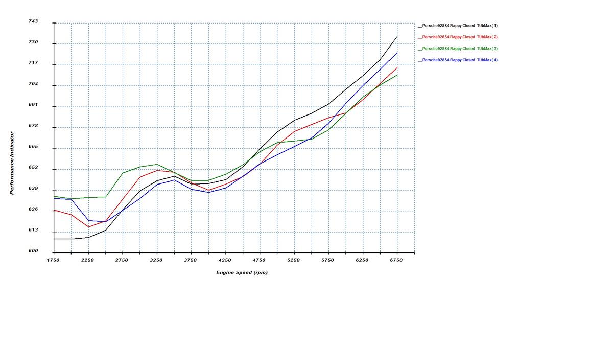
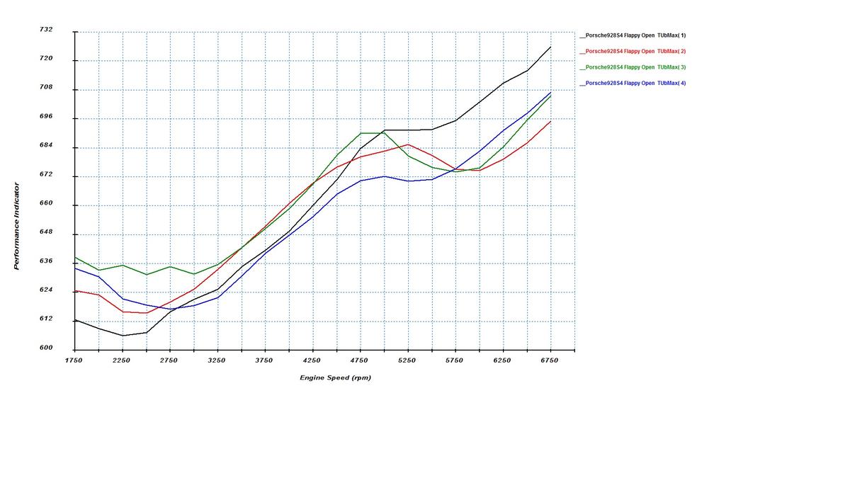
Here are some individual cylinder IMEP (think of it as gross torque) figures, both with flappy open and flappy closed for both banks.
Passenger side, flappy closed:
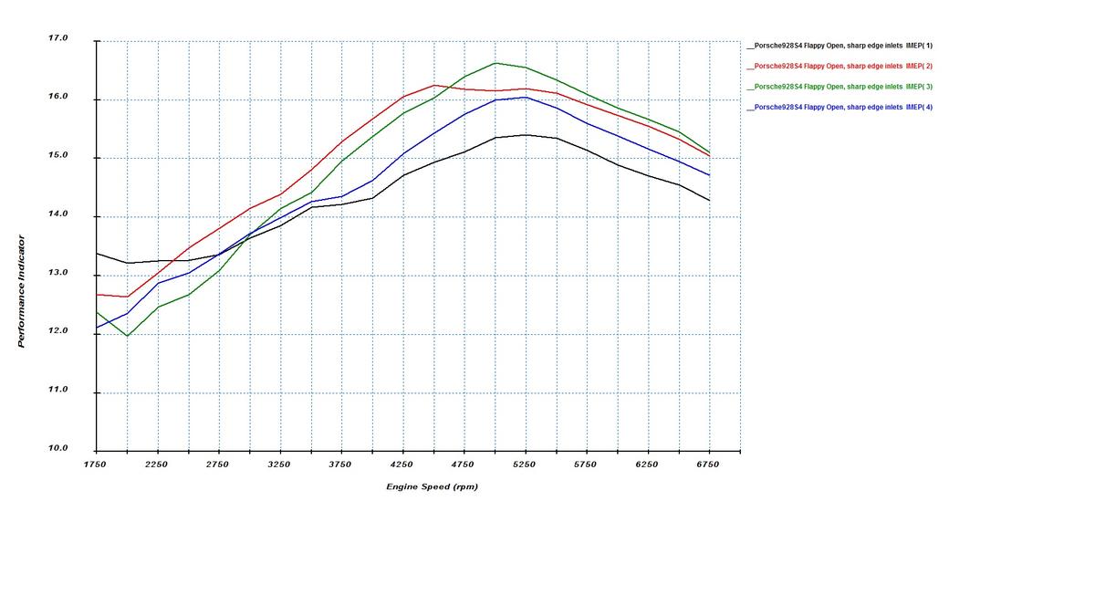
Passenger side, flappy open:
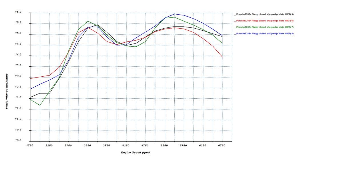
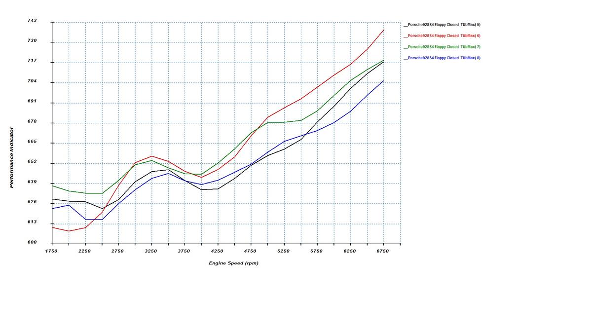
Driver side, flappy closed:
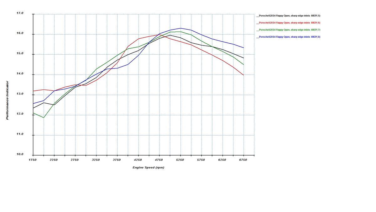
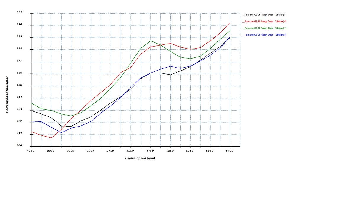
Driver side, flappy open:
The firing order is 1-3-7-2-6-5-4-8. Cylinder 3 causes 90-degree interference in cylinder 1 and 5 causes 90-degree interference with cylinder 6. The 180-degree interference is 2->3, 6->7, 8->5, 1->4.
At low rpms, the 90-degree interference helps. The exhaust pipes are too large for low rpms and therefore the velocity isn't sufficient. However, when two cylinders fire almost together into the exhaust manifold, the velocity goes up and that helps fill those cylinders. You can see 1&6 making more power than other cylinders at low rpms. Ford Coyote engine intentionally uses this effect on one of the banks by combining the two 90-degree separated cylinders.
The opposite is true for the 90-degree interference victims at high rpms. Now, the pipes are too small for two cylinders and 3 is still blowing out when 1 is at overlap. Similarly, 5 is still blowing when 6 is at overlap. At higher rpms, that hurts the power of those cylinders a lot.
At low rpms, 3, 7, 5, and 4 hurt because of 2, 6, 8, and 1 blow into those right at the overlap because of the 180-degree separation. At high rpms, event the stock manifold pipes are long enough, so the 180-degree interference isn't a big problem.
2&8 have it easy, as nobody is interfering with them. They do well at all rpms.
After accounting for these effects, one can see the expected patterns in IMEP between long runner and short runner cylinders. Eyeballing the results, the long runners (30cm + 10cm in the heads) would probably be better for this engine than the short runners (20cm + 10cm in the heads).
Another thing worth noting is that Porsche designers could have chosen to put the tight bend runners either on the passenger side or the driver side. They chose to put them in the driver side (feeding cylinders 5&8 on the driver side bank from the driver side plenum). This may have been a conscious choice. Because of the exhaust effects and runner length, the long runners for cylinders 2&3 fill really well compared to runners 1&4 at high rpms. Therefore, they probably wanted to make the runners 1&4 as straight as possible. In contrast, the long runners 6&7 don't have the same inherent top end advantage over the short runner 5&8. If one has to make the short runners really curved on one side, it's better to do that to 5&8 on the driver side. Runner 5 really takes "one for the team" in this design, being in the front with least hood clearance and not doing as well as 8 to start with...
Passenger side, flappy closed:
Passenger side, flappy open:
Driver side, flappy closed:
Driver side, flappy open:
The firing order is 1-3-7-2-6-5-4-8. Cylinder 3 causes 90-degree interference in cylinder 1 and 5 causes 90-degree interference with cylinder 6. The 180-degree interference is 2->3, 6->7, 8->5, 1->4.
At low rpms, the 90-degree interference helps. The exhaust pipes are too large for low rpms and therefore the velocity isn't sufficient. However, when two cylinders fire almost together into the exhaust manifold, the velocity goes up and that helps fill those cylinders. You can see 1&6 making more power than other cylinders at low rpms. Ford Coyote engine intentionally uses this effect on one of the banks by combining the two 90-degree separated cylinders.
The opposite is true for the 90-degree interference victims at high rpms. Now, the pipes are too small for two cylinders and 3 is still blowing out when 1 is at overlap. Similarly, 5 is still blowing when 6 is at overlap. At higher rpms, that hurts the power of those cylinders a lot.
At low rpms, 3, 7, 5, and 4 hurt because of 2, 6, 8, and 1 blow into those right at the overlap because of the 180-degree separation. At high rpms, event the stock manifold pipes are long enough, so the 180-degree interference isn't a big problem.
2&8 have it easy, as nobody is interfering with them. They do well at all rpms.
After accounting for these effects, one can see the expected patterns in IMEP between long runner and short runner cylinders. Eyeballing the results, the long runners (30cm + 10cm in the heads) would probably be better for this engine than the short runners (20cm + 10cm in the heads).
Another thing worth noting is that Porsche designers could have chosen to put the tight bend runners either on the passenger side or the driver side. They chose to put them in the driver side (feeding cylinders 5&8 on the driver side bank from the driver side plenum). This may have been a conscious choice. Because of the exhaust effects and runner length, the long runners for cylinders 2&3 fill really well compared to runners 1&4 at high rpms. Therefore, they probably wanted to make the runners 1&4 as straight as possible. In contrast, the long runners 6&7 don't have the same inherent top end advantage over the short runner 5&8. If one has to make the short runners really curved on one side, it's better to do that to 5&8 on the driver side. Runner 5 really takes "one for the team" in this design, being in the front with least hood clearance and not doing as well as 8 to start with...
Last edited by ptuomov; 02-01-2015 at 08:09 PM.
 02-01-2015, 11:23 PM
#182
Rennlist
Basic Site Sponsor
Basic Site Sponsor
And anything custom will not happen anywhere near $3,000.....never happen at $6,000! Too much time designing, modeling, fitting, building, testing, redesigning, building, retesting. I'm about 1/2 way through making a billet plenum, following the fantastic results I got with in testing the very restrictive, crude, welded version.
It's a terribly difficult task, in a very limited area, to get the needed runner lengths, combined with a decent plenum.
To even begin to make a copy of this work, I'd have to have the plenum "top" CNC made (and order 20 of them to offset the setup charges.) Even then, with the custom making of the sides, the bottom, the runners, and the cylinder head "adaptors", it would be a $10,000 manifold.
Custom stuff, unless you have unlimited time and all of the equipment required at your disposal, is terribly expensive.
__________________
greg brown

714 879 9072
GregBBRD@aol.com
Semi-retired, as of Feb 1, 2023.
The days of free technical advice are over.
Free consultations will no longer be available.
Will still be in the shop, isolated and exclusively working on project cars, developmental work and products, engines and transmissions.
Have fun with your 928's people!
greg brown
714 879 9072
GregBBRD@aol.com
Semi-retired, as of Feb 1, 2023.
The days of free technical advice are over.
Free consultations will no longer be available.
Will still be in the shop, isolated and exclusively working on project cars, developmental work and products, engines and transmissions.
Have fun with your 928's people!
02-02-2015, 04:40 PM
#183
Addict
Rennlist Member
Rennlist Member
Join Date: Feb 2004
Location: Monterey Peninsula, CA
Posts: 2,374
Likes: 0
Received 16 Likes
on
12 Posts
Here's an interesting manifold for a turbocharged 944 s2 with 16V head and 3.0L displacement. It's fabricated from a stock 944 S2 manifold and an aftermarket plenum cover originally meant for a Toyota (I think). What's remarkable about the manifold is that, once you factor out the impact of boost, it produces an almost perfectly flat normally aspirated torque curve between 2500 and 7000 rpm. I don't quite understand how the builder did it, maybe he's setting the Helmholtz peaks around the natural camshaft peak? https://rennlist.com/forums/944-turb...o-project.html rpm, TT3 torque, TT3 boost psi, Torque per abs psi, TT3 torque rescaled to ambient, Stock 16v 3L torque 2550 250 6 12.1 178 195 2740 421 19 12.5 184 197 3050 501 25 12.6 186 200 3510 507 26 12.5 183 206 4020 509 26 12.5 184 207 4530 510 26 12.5 184 206 5070 514 25 12.9 190 205 5520 518 25 13.0 192 198 6030 502 24 13.0 191 182 6500 495 23 13.1 193 160 7050 451 22 12.3 181 130
Many years ago, I posted a similar torque table chart from a supercharged mustang with an Opcon compressor.
Cheers
Sent from my iPhone using Rennlist
02-02-2015, 04:56 PM
#184
Rennlist Member
I think to gregs point, to make a full range manifold, this is true.... I got to believe, there are manifolds that are production now that can be bolted on or copied and put on the 928 with a adapter plate. sure, you might lose some of the mid or low range performance, but by definition, real "performance" is 4500rpm and higher!! 
someday, we will see a bolt on kit for the 928S4 .... I hope!
someday, we will see a bolt on kit for the 928S4 .... I hope!
02-02-2015, 09:34 PM
#185
Nordschleife Master
Thread Starter
Have you gentlemen (and ladies?) noticed one thing about the 928 S4 exhaust manifold: There are two different length primary pipes in that manifold as well! The difference isn't huge, but the variation is 15cm vs. 20cm. I hadn't thought about it before checking my eyeball measurements with the actual part.
So, the plot thickens...
Not only are the intake manifold runners of two different length, but so are the exhaust manifold primary runners. Furthermore, they are paired up systematically: All long intake runners get a short exhaust runner and all short exhaust runners get a long exhaust runner. It's almost as if it were designed that way! ;-) LOL!
I am verifying this with a computer right now, but it appears that there's some resemblance of the balance in the torque curve. With the long intake runners which boost mid range, the short exhaust stubs do less. With the short intake runners which aren't doing as much at the mid range, the longer exhaust stubs do a little more. It's a little like the current rage of redistributing income after the fact! ;-)
One piece of evidence arguing against this is that the 32V S3 already used essentially similar exhaust manifold but that engine has equal length intake runners. As a counterpoint, it seems that a lot of the S3 designs already were aware of the subsequent S4 designs.
At this point the point is of course moot: the exhaust manifold is what it is, regardless of the designers intentions.
02-03-2015, 12:10 AM
#186
Nordschleife Master
Thread Starter
Knocks have come up in a couple of posts in this thread.
Here are some predictions about knock probability for different cylinders. The below graphs plot the maximum temperature of the unburned mixture during the cycle. That's not the same as the knock probability, but at a given rpm the cylinders that have a higher max unburned mixture temp are more likely to knock at that rpm.
At high rpms, 1 & 6 are likely to knock according to this simulation model. This is because the cylinders have a lot of residual exhaust gas in them, caused by 90-degree exhaust interference. I would speculate that installing long tube headers would reduce the high rpm tendency of 1 & 6 to knock.
At mid range rpms, the long runners 2, 3, 6, 7 are likely to knock. This is mostly because they have longer runners that fill the cylinder better at mid range rpms. Here, the solution would be just to back off timing. Unfortunately, we don't have individual cylinder ignition trim, other than the knock retard.
At low rpms, 3 & 7 are most likely to knock. They are both 180-degree interference victims and they both have long runners that fill well at lower rpms.
I don't know if these predictions correlate with reality of knock logs of stock S4. My knock experience is with a turbo car and it has a very different exhaust manifold.
02-03-2015, 09:18 AM
#188
Nordschleife Master
Thread Starter
#6 is really knock prone according to the simulation with the stock intake and exhaust manifolds. Long tube headers should help a lot in reducing the #6 knocks at higher rpms, even if the long intake runner still fills very well. The largest contributor to knock is in my opinion the residual exhaust gas, and cylinder #5 blows its exhaust gas partially into #6 when #6 exhaust valve is closing.
02-03-2015, 02:49 PM
#189
Three Wheelin'
Join Date: Aug 2003
Location: DFW
Posts: 1,641
Likes: 0
Received 0 Likes
on
0 Posts
Not only are the intake manifold runners of two different length, but so are the exhaust manifold primary runners. Furthermore, they are paired up systematically: All long intake runners get a short exhaust runner and all short exhaust runners get a long exhaust runner. It's almost as if it were designed that way! ;-) LOL!
~~~~
I have always wanted to ditch the cast intake and build sliding trumpets like Mazda's insane 4-rotor Wankel rotary in the 787B LeMans winner. The V8 makes that difficult at best, more like a sliding-pipe dream for feasibility.
 02-03-2015, 09:33 PM
#190
Nordschleife Master
Thread Starter
There are all sorts of interesting things that one can study with this new sim software.
With the stock intake manifold that has unequal runners, there's a way to try different custom, unequal length headers and see how well they can compensate for the intake manifold. It's not the final answer, exhaust is hard to model, but it'll get you to the ball park I believe.
Another thing is that since Hans is making those flanges, this software will allow making "educated guesses" about how each potential manifold configuration might work. Again, it's not going to get you all the way there, but it's going to get you to a lot better starting point than just "uneducated" guessing.
The next experiment I'll run is how the manifold "should" "in theory" respond to 5/8" plenum spacers on both sides. This is from the resonance perspective, and not taking into account any changes in flow coefficients.
Last edited by ptuomov; 02-03-2015 at 11:42 PM.
02-03-2015, 11:51 PM
#191
Nordschleife Master
Thread Starter
Below is a quick run that predicts the impact of installing spacers between the intake manifold and the plenum covers. I am assuming 5/8" thickness for the spacer. As before, ignore the level and focus on changes.
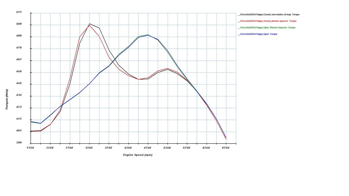
There is absolutely nothing shocking here. The only thing that the spacer does, assuming that it doesn't change the runner flow coefficients, is that it moves the flappy closed torque peaks a tiny bit down to lower rpms. There's no practically relevant impact in the flappy open mode.
This leads to the following conclusions. You can install a spacer if you want to move the flappy-closed torque peak down to a slightly lower rpm. In addition, you can install it as a part of a intake manifold porting effort. If the spacer helps you to get higher flow coefficients for the problem runners, this is additive to power (furthermore not modeled in the above software model.) What you shouldn't do, at least based on these simulations, is to install the spacers and expect 10hp more at the top end.
02-04-2015, 01:54 AM
#192
Addict
Rennlist Member
Rennlist Member
Join Date: Feb 2004
Location: Monterey Peninsula, CA
Posts: 2,374
Likes: 0
Received 16 Likes
on
12 Posts
Knocks have come up in a couple of posts in this thread. Here are some predictions about knock probability for different cylinders. The below graphs plot the maximum temperature of the unburned mixture during the cycle. That's not the same as the knock probability, but at a given rpm the cylinders that have a higher max unburned mixture temp are more likely to knock at that rpm. At high rpms, 1 & 6 are likely to knock according to this simulation model. This is because the cylinders have a lot of residual exhaust gas in them, caused by 90-degree exhaust interference. I would speculate that installing long tube headers would reduce the high rpm tendency of 1 & 6 to knock. At mid range rpms, the long runners 2, 3, 6, 7 are likely to knock. This is mostly because they have longer runners that fill the cylinder better at mid range rpms. Here, the solution would be just to back off timing. Unfortunately, we don't have individual cylinder ignition trim, other than the knock retard. At low rpms, 3 & 7 are most likely to knock. They are both 180-degree interference victims and they both have long runners that fill well at lower rpms. I don't know if these predictions correlate with reality of knock logs of stock S4. My knock experience is with a turbo car and it has a very different exhaust manifold.
(Pectel and Motec have individual cylinder trim for fueling and timing and can address the individual cylinder tuning issues that are unavailable in the LH...)
On another note, Have you run any simulations to see what the optimum length of runner and header tube would have to be in a stock 32v S4 bore/stroke/valve setup at atmospheric and also with positive pressure?
In addition, what velocity are you using for flow through the exhaust header? Was the velocity based on a 1.625" ID header?
Did you use a specific Lambda and timing for the sim?
Sent from my iPhone using Rennlist
02-04-2015, 09:10 AM
#193
Nordschleife Master
Thread Starter
On another note, Have you run any simulations to see what the optimum length of runner and header tube would have to be in a stock 32v S4 bore/stroke/valve setup at atmospheric and also with positive pressure?
In addition, what velocity are you using for flow through the exhaust header? Was the velocity based on a 1.625" ID header?
Did you use a specific Lambda and timing for the sim?
In addition, what velocity are you using for flow through the exhaust header? Was the velocity based on a 1.625" ID header?
Did you use a specific Lambda and timing for the sim?
The velocity is what it is. It'll depend on the rpm. Here's the exhaust port velocity at 6250 rpm. The units are Mach index on y and crankshaft degrees (aligned by TDC) on x:
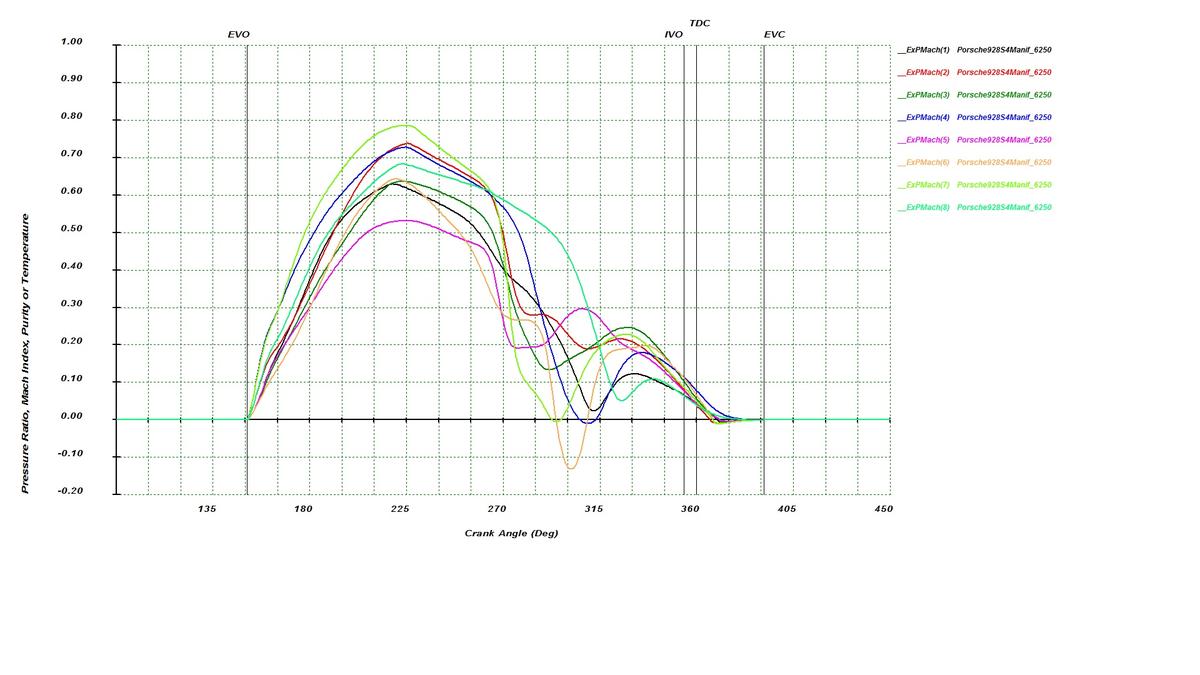
I could also plot what it's in the primary stubs, but the shape will look almost exactly the same (just adjust it for area since it's subsonic flow at that point of the port and header).
Take a look at what is happening with cylinders 5 and 6. Cylinder 5 has a pretty low velocity compared to other cylinders at the first velocity peak. Why is that? It's because cylinder 5 is blowing at the same time as cylinder 6 is trying to finish its exhaust stroke. Cylinder 6 really hurts from this, see 90 degrees later (contemporaneously in clock time) the cylinder 6 exhaust port actually shows exhaust gas flowing at negative velocity, that is, back into the cylinder. At 6250 rpm, the 90-degree interference is a big problem.
My hunch is that a properly sized stepped long-tube headers would help a lot with this problem and reduce cylinder 6 knocks significantly. Like those Greg Brown S3 headers (not his S4 headers) that were discussed in a colorful way here last year. The first pipe of those headers is and should be significantly smaller than 1 3/4" OD pipe. A 1 3/4" OD primary first step is IMO too large for even most hot rodded strokers that make under 500 hp. That's my opinion on headers, in my opinion most S4's would be better of reducing the area from the stock port into a slightly smaller primary.
Lambda and timing are determined from the combustion model. There are a couple of combustion models available. I am using one of them for no particular reason. Only when we get to the point where we can measure the cylinder pressure traces (that system is very hard to install) I can try to match the combustion more closely with a more accurate model.
02-04-2015, 11:06 AM
#194
Instructor
Join Date: Oct 2005
Location: Finland
Posts: 137
Likes: 0
Received 0 Likes
on
0 Posts
Interesting findings, now we know why the 32V engine responds nicely to exhaust changes, specially good headers.
However, I remember reading one of the David Vizard books where he mentioned that dual-plane crank engines doesn't respond to primary pipe length changes
as long as they are in range of 28 - 40 inches. The MSDS primary lengths are 32, 26, 24 & 23 inches(valve face to collector), perhaps this will be the reason
for minimal gains together with uber short collector, go figure
Kind of OT for this thread, but talked some time ago with guy who has also experience of tuning stock ECUs. He mentioned that he's using WB datalogger which is capable of high enough
WBO2 sampling frequency to catch short AFR changes at higher rpms. Sometimes he has seen very quick rich conditions due to sudden exhaust suction, this will lead to lean cylinder AFR and possible knocks.
Only way is to add some fuel there even it looks like AFR is already in correct range from ECU point of view. At least, it will save lot's of expensive dyno time and you don't need to tune using trial and error method.
02-04-2015, 11:53 AM
#195
Addict
Rennlist Member
Rennlist Member
Join Date: Feb 2004
Location: Monterey Peninsula, CA
Posts: 2,374
Likes: 0
Received 16 Likes
on
12 Posts
I am still trying to get the bone stock '87 S4 modeled right. The exhaust manifold is modeled as close to my measurements as possible. It's four 42mm diameter primariers and then pipe sections and collectors to 50mm outlet. I used a thick rope to measure the centerline lengths. The velocity is what it is. It'll depend on the rpm. Here's the exhaust port velocity at 6250 rpm. The units are Mach index on y and crankshaft degrees (aligned by TDC) on x: I could also plot what it's in the primary stubs, but the shape will look almost exactly the same (just adjust it for area since it's subsonic flow at that point of the port and header). Take a look at what is happening with cylinders 5 and 6. Cylinder 5 has a pretty low velocity compared to other cylinders at the first velocity peak. Why is that? It's because cylinder 5 is blowing at the same time as cylinder 6 is trying to finish its exhaust stroke. Cylinder 6 really hurts from this, see 90 degrees later (contemporaneously in clock time) the cylinder 6 exhaust port actually shows exhaust gas flowing at negative velocity, that is, back into the cylinder. At 6250 rpm, the 90-degree interference is a big problem. My hunch is that a properly sized stepped long-tube headers would help a lot with this problem and reduce cylinder 6 knocks significantly. Like those Greg Brown S3 headers (not his S4 headers) that were discussed in a colorful way here last year. The first pipe of those headers is and should be significantly smaller than 1 3/4" OD pipe. A 1 3/4" OD primary first step is IMO too large for even most hot rodded strokers that make under 500 hp. That's my opinion on headers, in my opinion most S4's would be better of reducing the area from the stock port into a slightly smaller primary. Lambda and timing are determined from the combustion model. There are a couple of combustion models available. I am using one of them for no particular reason. Only when we get to the point where we can measure the cylinder pressure traces (that system is very hard to install) I can try to match the combustion more closely with a more accurate model.
BTW, I think Omega has both the plug extender type and in plug pressure sensors... I think the in plug sensors were pricier than the extender ring type.
It would be interesting to see what the pressures look like across the cycles and rpm..
In my Christmas gift, I would love to see pressure, egt, lambda and timing for an equal length intake and exhaust with variances for atmospheric to about 2 bar with stock S4 and GT/S3 cams..

(I did say Christmas!!
)Cheers
Sent from my iPhone using Rennlist