
Center Console Lighting Problem: Blowing Fuse
 04-15-2012, 07:15 PM
#16
Addict
Rennlist Member
Rennlist Member
Given that the pod was one of the things being worked on, I'd definitely be suspecting a pinched BK/BL wire around the pod somewhere. There are a lot of those wires near metal parts where they could be pinched and shorted to ground. There are BK/BL wires leading to four out of five of the pod switches (to power the lamps that back-light the symbol on each switch; the main light switch's back light does not dim and is supplied by a BK wire, not a BK/BL wire).
If it comes to loosening or removing the pod, it's not as big job as you might expect. I've had my instrument cluster out at least half a dozen times (and the entire pod off once) in the last year and now have cluster removal down to about 15 minutes for removal. See Schocki's thread "15 minute instrument pod removal update and instrument light bulbs for an OK price" for instructions.
Idea: if you don't wait to keep wasting fuses, you could switch your diagnostic technique from "try something, then see if it is fixed it by re-powering and see if the fuse blows" to "use an ohmmeter (DMM in resistance mode) or a continuity tester from the BK/BL wire at the dimmer rheostat or at the "instrument cluster resister" (see below) to ground. You should see continuity (0 Ω, continuity tester light on or tone) until you find the short. Once you fix the problem, you'll see higher resistance. You should probably do this with fuse #9 removed (you do not want to power the circuit while doing this testing).
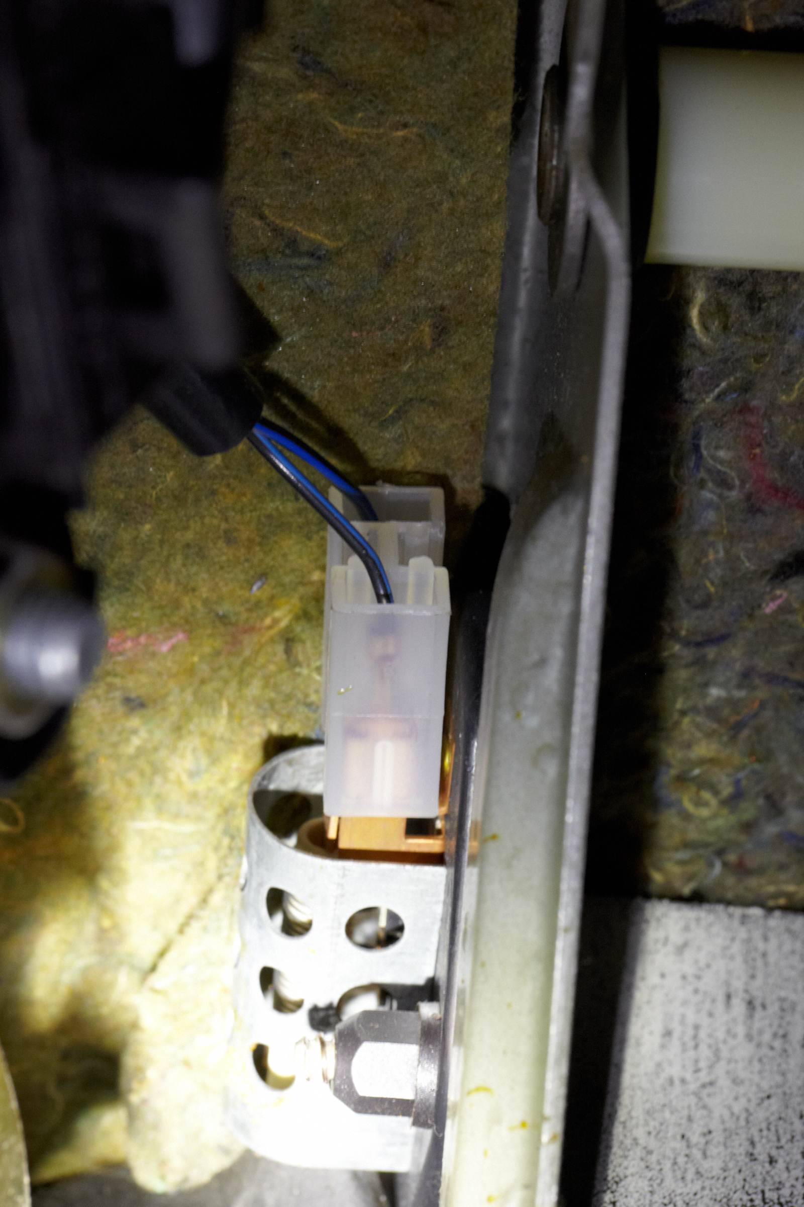
One other thing comes to mind... there's a fairly exposed resistor used to current-limit the power provided to the instrument back-lighting for the instrument cluster. That resistor has a couple of BK/BL wires attached to its connector; one is connected to the BK/BL dimmer rheostat wire, the other is connected to the instrument cluster. I suppose you could also try disconnecting it; that would be one way of further narrowing down where the problem might be. If you disconnect the connector and the fuse doesn't blow (or you're not seeing a short anymore, using the alternative diagnostic technique I mentioned above), then that would indicate a short somewhere between the resistor and the instrument cluster.
The resistor is located on the left bracket supporting the brake pedal pivot:

If it comes to loosening or removing the pod, it's not as big job as you might expect. I've had my instrument cluster out at least half a dozen times (and the entire pod off once) in the last year and now have cluster removal down to about 15 minutes for removal. See Schocki's thread "15 minute instrument pod removal update and instrument light bulbs for an OK price" for instructions.
Idea: if you don't wait to keep wasting fuses, you could switch your diagnostic technique from "try something, then see if it is fixed it by re-powering and see if the fuse blows" to "use an ohmmeter (DMM in resistance mode) or a continuity tester from the BK/BL wire at the dimmer rheostat or at the "instrument cluster resister" (see below) to ground. You should see continuity (0 Ω, continuity tester light on or tone) until you find the short. Once you fix the problem, you'll see higher resistance. You should probably do this with fuse #9 removed (you do not want to power the circuit while doing this testing).
One other thing comes to mind... there's a fairly exposed resistor used to current-limit the power provided to the instrument back-lighting for the instrument cluster. That resistor has a couple of BK/BL wires attached to its connector; one is connected to the BK/BL dimmer rheostat wire, the other is connected to the instrument cluster. I suppose you could also try disconnecting it; that would be one way of further narrowing down where the problem might be. If you disconnect the connector and the fuse doesn't blow (or you're not seeing a short anymore, using the alternative diagnostic technique I mentioned above), then that would indicate a short somewhere between the resistor and the instrument cluster.
The resistor is located on the left bracket supporting the brake pedal pivot:
Last edited by Ed Scherer; 04-15-2012 at 07:35 PM.
 04-15-2012, 07:25 PM
#17
Addict
Rennlist Member
Rennlist Member
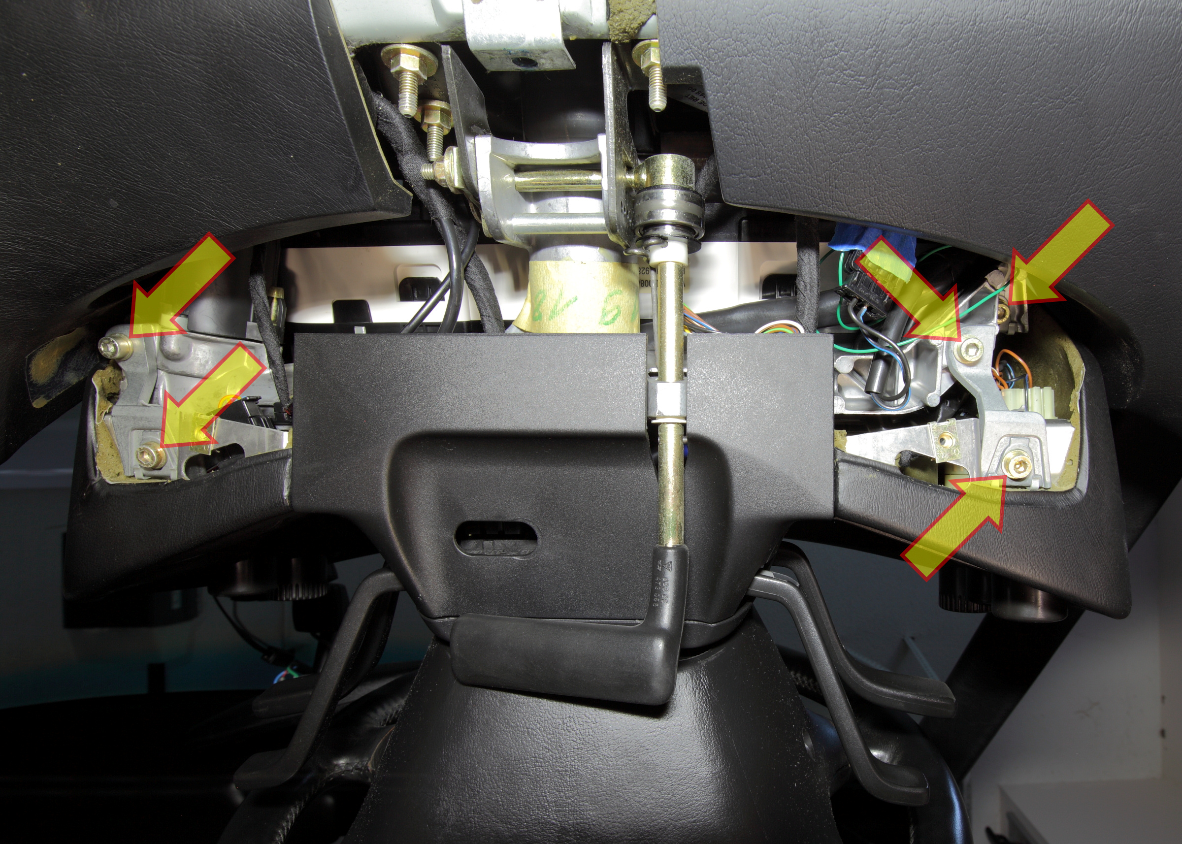
Ignore the upper-right arrow on this annotated photo; the other four arrows show the four bolts: one bolt at each end of the two brackets. IIRC, I think you need to remove the knee bloster to get this view.
I've done that--nothing obvious. One question though. Is there only one plug for the clock (with four leads)? The bulb sticks out the back and there's no direct connector for that, right? The bulb screws in and is powered by internal connections stemming from the four-wire plug, right?

Yes (I think); yes; yes.
That's because the HVAC and clock lights are dimmable; and the cigar lighter/ash tray light is not. The latter is thus still powered (if the lights are on) even if the dimmer is removed from the circuit.
04-15-2012, 07:54 PM
#18
Pro
Thread Starter
Join Date: May 2008
Location: Charlotte, NC
Posts: 580
Likes: 0
Received 0 Likes
on
0 Posts
Thanks a ton Ed. That gives me a lot to go on.
Too funny. Yes, I can ramble.
Thanks for confirming this. That's what I was thinking.
Thanks for everyone's help. I have family responsibilities for the rest of the night. Then comes the work week which can be all consuming. I may not post back until next weekend unless I can find some more time tonight to work on it.
Dan
That's three questions.
That's because the HVAC and clock lights are dimmable; and the cigar lighter/ash tray light is not. The latter is thus still powered (if the lights are on) even if the dimmer is removed from the circuit.
Thanks for everyone's help. I have family responsibilities for the rest of the night. Then comes the work week which can be all consuming. I may not post back until next weekend unless I can find some more time tonight to work on it.
Dan
04-16-2012, 03:23 PM
#19
Advanced

Join Date: Apr 2012
Posts: 98
Likes: 0
Received 0 Likes
on
0 Posts
I apologize in advance for being a "newb".
Is there a pic/ diagram for dummies for "switches and controls" for an '84 928?
I've seen a lot of advanced wiring diagrams on here (good stuff), but can't find the above.
I picked up my 1st 928 on Friday and can't seem to turn the dash lights on (the warning lamps work). I figured that the rheostat was on the headlight switch (as most), but it appears to be only a 3-position switch. My Saab 9-3 Aero Convertible has a separate control for the dimming function.
Thanks in advance for the assistance.
04-19-2012, 12:14 PM
#21
Pro
Thread Starter
Join Date: May 2008
Location: Charlotte, NC
Posts: 580
Likes: 0
Received 0 Likes
on
0 Posts
Idea: if you don't wait to keep wasting fuses, you could switch your diagnostic technique from "try something, then see if it is fixed it by re-powering and see if the fuse blows" to "use an ohmmeter (DMM in resistance mode) or a continuity tester from the BK/BL wire at the dimmer rheostat or at the "instrument cluster resister" (see below) to ground. You should see continuity (0 Ω, continuity tester light on or tone) until you find the short. Once you fix the problem, you'll see higher resistance. You should probably do this with fuse #9 removed (you do not want to power the circuit while doing this testing).
With the pod dimmer connected, the fuse will blow but the pod stays illuminated. In my mind, this means that the electricity is going through the pod dimmer, to central circuit board and fuse #9 and then passed out again towards the center console at which point it is shorting somewhere and blowing the fuse. Since the short is happening after fuse #9, the pod stays illuminated even though fuse #9 in blown.
Again, by my reasoning.... With the dimmer removed, the pod does not illuminate, the electricity does not get passed to fuse #9 and the fuse does not blow.
So, my conclusion at this point is that the short is occurring somewhere between fuse #9 and center console and therefore if fuse #9 is removed and I'm testing continuity at the dimmer switch, I'm barking up the wrong tree.
Is my thought process flawed is some way? If, not, how can I use the multimeter to help locate the short without blowing fuses. I guess I would need to take out the fuse, turn on the headlights and put one contact of the multimeter on the CE panel at the #9 fuse location and one end on the terminal at the (HVAC disconnected) and see if I get continuity. If not then I can say the short is somewhere in between? I have a multimeter and your basic light-bulb circuit tester.
Thanks,
Dan
04-19-2012, 01:53 PM
#22
Electron Wrangler
Lifetime Rennlist
Member
Lifetime Rennlist
Member
Dan just use the continuity/ohms mode instead just in place of output end of the fuse (lower) and to ground. It will be virtually 0 ohms as long as you still have a short and perhaps more like 0.5 ohms when you don't - noticeably different.
The continuity tone if used will likely sound either way since this is very low resistance - so don't rely on that.
Alan
The continuity tone if used will likely sound either way since this is very low resistance - so don't rely on that.
Alan
04-22-2012, 02:07 PM
#23
Pro
Thread Starter
Join Date: May 2008
Location: Charlotte, NC
Posts: 580
Likes: 0
Received 0 Likes
on
0 Posts
OK, so I'm having a good looking around behind the stereo and have a few questions. There's a few stray/unused wires back there that I'd like to identify. I don't think any of these will explain my short, but it's probably best to identify them before moving on...
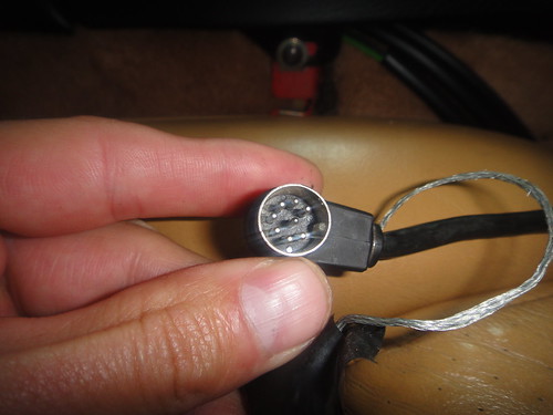
1) Suspect this is part of old stereo wiring??? Sitting loose back there.
2) Part of old stereo harness. Brown wire with yellow stripe. Suspect it should be wired to dimming function of stereo. I don't understand why it comes into the harness but then also out of the harness again. Should there be another end that I need to find that connects to the wire coming out of the harness?
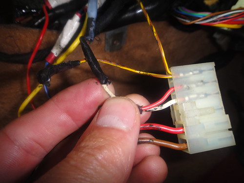
3) Brown wire coming out of same wire bundle as all the other stereo wires. It was covered in electrical tape so wasn't causing the short; just wondering what it's doing back there. Could this be for the dimming function of the stereo (not the brown and yellow stripe wire from photo #2).

4) Black wire running with antenna is taped off.
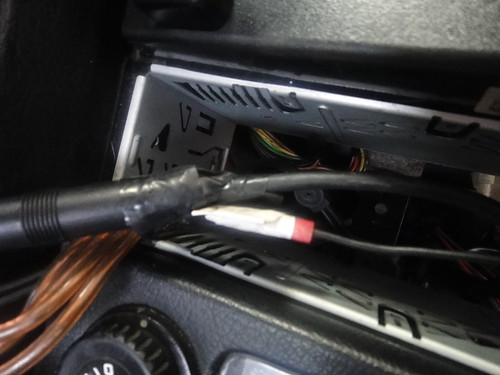
Other than those things, things seem to be in good order back there. All other wires seem to be in good condition, well insulated, not touching metal, etc...
Thanks,
Dan
1) Suspect this is part of old stereo wiring??? Sitting loose back there.
2) Part of old stereo harness. Brown wire with yellow stripe. Suspect it should be wired to dimming function of stereo. I don't understand why it comes into the harness but then also out of the harness again. Should there be another end that I need to find that connects to the wire coming out of the harness?
3) Brown wire coming out of same wire bundle as all the other stereo wires. It was covered in electrical tape so wasn't causing the short; just wondering what it's doing back there. Could this be for the dimming function of the stereo (not the brown and yellow stripe wire from photo #2).
4) Black wire running with antenna is taped off.
Other than those things, things seem to be in good order back there. All other wires seem to be in good condition, well insulated, not touching metal, etc...
Thanks,
Dan
05-05-2012, 07:17 PM
#24
Pro
Thread Starter
Join Date: May 2008
Location: Charlotte, NC
Posts: 580
Likes: 0
Received 0 Likes
on
0 Posts
bump. Still looking for help with identifying the wires in my previous post. I had the knee bolster off on the driver's side and looked at the bolts that secure the pod--no wires shorting out there and all appears to be in good order.
05-05-2012, 09:53 PM
#25
Electron Wrangler
Lifetime Rennlist
Member
Lifetime Rennlist
Member
The big plug is the head unit preamp-out to the amp under the sill cover.
The wire attached to the antenna is the amp wire needs to be opowered when the head unit is on or else your reception will be pretty crappy.
Brown/yellow is the alarm wire (protecting the radio).
Brown on a Porsche is always ground.
Alan
The wire attached to the antenna is the amp wire needs to be opowered when the head unit is on or else your reception will be pretty crappy.
Brown/yellow is the alarm wire (protecting the radio).
Brown on a Porsche is always ground.
Alan
05-11-2012, 02:22 AM
#26
Advanced
Join Date: Apr 2012
Posts: 98
Likes: 0
Received 0 Likes
on
0 Posts
I stumbled upon this as my '84's dashlights and center console lights do not work (warning lamps ann stereo lights do, however). Any suggestions would be appreciated.
As a newbie owner and a life-long fan of 928s might I add that you guys are frikkin' awesome. The tech data on this site is incredible.
As a newbie owner and a life-long fan of 928s might I add that you guys are frikkin' awesome. The tech data on this site is incredible.
05-11-2012, 10:26 AM
#27
Rennlist Member
Rennlist Site Sponsor

You are looking for a place where a black/blue wire is shorted to the body - nothing else. Look for a screw thru the wire, pinched wire, etc.
08-16-2012, 11:46 AM
#29
Instructor
Join Date: Jun 2010
Location: London, UK
Posts: 169
Likes: 0
Received 0 Likes
on
0 Posts
My '90 S4 has exactly this same problem. Was there any resolution? I'd given up on it and taken it to my friendly Porsche specialist but he can`t find the short. As Manfred hasn't reposted I assume he's fixed it.
Can you help Manfred?
Can you help Manfred?
08-16-2012, 06:46 PM
#30
Rennlist Member
Rennlist Site Sponsor
Get:
- A couple of feet of lamp cord (sometimes called zip cord) - the brown or white two-conductor wire used to hook a table lamp to the wall socket.
- A small 12-volt bulb, such as a parking light bulb.
- Two 1/4" flat male spade connectors.
Put the connectors on one end of the wire, the bulb on the other end, so that when you put power on one connector and ground the other, the bulb lights up.
Remove the fuse for the instrument lights. Plug the two connectors in where the fuse legs were. Turn the lights on. If you have a short to ground, the bulb will glow with full brightness. If you remove the short to ground, the bulb will glow dimly, as it is now in series with the instrument light bulbs. This will let you search for the short without blowing a fuse or burning the harness.

