When you click on links to various merchants on this site and make a purchase, this can result in this site earning a commission. Affiliate programs and affiliations include, but are not limited to, the eBay Partner Network.
I recently had an intermitted working speedo/odometer. So sometimes when hitting serious bumps on the road, my speedo/odometer started working for a while....
Afterwards when trying again, my speedo/odometer did not work anymore at all even when hitting bumps on the road...as if it was completely dead.
I measured directly on the rivets if I had pulse (coming from speedsensor) and 12V at the back of the plastic circuit board and it did. So there was feed....
However it did not work, even when replacing it by another speedo/odometer...
Remark : I also found on the web that there should be 12V on H1 (plug H, pin1 on CEPanel) when putting 12V contact on...but I never have 12V there...
I am totally lost now, does any one have some further analysis of what could be wrong ?????
yes the speedo clocks give lots of problems.it requires taking the head unit(clocks) out and stripping and cleaning every part of it.there are some great links on the site for it just search"speedo".mine has the speedo intermittently not working,fuel gauge reading slightly lower if the lights are on,temp gauge slightly higher if the lights are on.voltmeter reads 2 volts lower than actual all the time.this job is on the end of my jobs to do list,now i know whats going on im happy to live with mine for the short term anyway.
Had the same problem. Here is my post that I put on rennlist after fixing it. Hope it helps.
Leo.
So, a year later I finally got around to fixing the speedo: it turns out there were three problems so I was getting a bit frustrated, but perseverence won (with help from the forum of course, thanks guys!)
In summary the problems and fixes were:
1) I replaced the speedo sensor at the back of the differential, since it was missing. I measured resistance between the connectors. By moving the car just a bit by hand you can already see it switching between open/closed.
2) flexible circuit board at the back of the instrument pod: The rivets were not making good contact with the printed circuit. Rather than soldering it I put some silver paint on it (the conductive paint you can use for fixing rear window demisters as well), and then put pliers on the rivet and firmly pressed it. The rivets now are fixed and cannot move anymore. And I used the mulitmeter to measure resistance between the rivet and the corresponding pin next to it. And also between the rivet and the connector at the plug. So, problem two tackled, but still no speedo...
3) Then I followed the wires and measured connectivity between terminals T1 and T2 and the wires to the sensor at the back of the car in the spare wheel well. (plug 'T' on the CE panel, which are in alphabetial order from left to right, skip the letter 'I' since it is not there and also skip counting the three smaller plugs. T1 and T2 are the bottom left and bottom right wires) Be sure to disconnect the wires at the back otherwise you cannot individually measure each wire that runs from the front to the back of the car. Also pull out the plug 'T' when measuring.
Resistance between T1 and one of the wires at the back was zero, so that was in fine order. The other one was not. So that is problem two. To now quickly test the speedo I ran a separate wire from the back connector to the front T2 with the T plug in place. I now got an open/close signal all the way to the pod, BUT still, when driving no speedo... By now I was getting a bit frustrated. So I put it to rest and did some further thinking. I also had no intention to pull out half my interior to run a new wire from the back to the front.
So here's the alternative solution, which I thought I would share with you, and may save you all time looking for bad ground contacts at the pod: I notived I had no wire from plug H2 (which is connected to T2 and supposed to be the ground contact for the speedo. I have read other posts saying they also did not have a H2 wire. So why on earth would one have a wire running from the speedo sensor all the way to the front of the car to the CE-panel, or even to the instrument pod to be connected to the ground contact over there? One could also connect one of the speedo sensor wires to a ground contact at the back of the car. Thus avoiding all the possible bad contact in the original set up (i.e. connectors from speedo sensor to the wire running all tha way from the back of the car to plug T2 and then from T2 to H2 and to a ground contact or even further to the pod and then to the ground contact). Sure enough: this works, provided that your other ground contact in the pod are o.k. it now ALL works. I have a working speedo, with no hesitation at all!!!
And I needed it since the yearly mandatory legal check was due and without a working speedo I cannot drive the shark...
I am one happy man. At the same time I also fixed the fuel gage (bad contacts at the rear plug.), the economy indicator (not that I am using it :-).
Only thing to do now is the odometer (the little rubbery plastic wheel has disintegrated completely).
I will post the same story in one of the other posts I used so people can use it for future reference.
And thanks to the amazing photo posts on how to take out the pod, and the practice I got, I can now take out the pod in 20 minutes or so, almost blindfolded :-) and put it back in 40 minutes.
One other thing to share: to make testing easy I took the whole pod out, and with the steering wheel of, I put the instrument panel in place with the three connector plugs. Then I lifted the rear of the car (I have a two column garage bridge at home), blocked the front wheels. Then started it and in first gear slowly turned the back wheels by touching the gas pedal. Be sure the car is properly lifted so it can in no circumstance fall to the floor and send you off into your garage wall :-) This setup can then be used for some nice trial and error diagnosis without having to take the pod out over and over again.
I have been chasing a similar problem. I have cleaned every connection in the series between the cluster and the sensor and checked every ground.
Best guess if the problem was intermitent before and total now, check the edge connector that connects the speedo, etc. to the flexible circuit on the back of the cluster. The connectors inside get deformed such that they do not provide proper contact. I used a dental pick to engage each side of each terminal and carefully bend it back into the open space.
In my case I get 8 volts at the sensor connection rivet on the back side of the cluster, with a solid 12+ on the voltage supply rivet so I know the voltage drop is internal to the speedo itself. I had the entire cluster checked by PaloAlto and they say it tests good. I still have some work to do before the car gets on the road to check the speedo so I can not claim success, just a lot of knowledge about all of the connections involved.
Had the same problem. Here is my post that I put on rennlist after fixing it. Hope it helps.
Leo.
So, a year later I finally got around to fixing the speedo: it turns out there were three problems so I was getting a bit frustrated, but perseverence won (with help from the forum of course, thanks guys!)
In summary the problems and fixes were:
1) I replaced the speedo sensor at the back of the differential, since it was missing. I measured resistance between the connectors. By moving the car just a bit by hand you can already see it switching between open/closed.
2) flexible circuit board at the back of the instrument pod: The rivets were not making good contact with the printed circuit. Rather than soldering it I put some silver paint on it (the conductive paint you can use for fixing rear window demisters as well), and then put pliers on the rivet and firmly pressed it. The rivets now are fixed and cannot move anymore. And I used the mulitmeter to measure resistance between the rivet and the corresponding pin next to it. And also between the rivet and the connector at the plug. So, problem two tackled, but still no speedo...
3) Then I followed the wires and measured connectivity between terminals T1 and T2 and the wires to the sensor at the back of the car in the spare wheel well. (plug 'T' on the CE panel, which are in alphabetial order from left to right, skip the letter 'I' since it is not there and also skip counting the three smaller plugs. T1 and T2 are the bottom left and bottom right wires) Be sure to disconnect the wires at the back otherwise you cannot individually measure each wire that runs from the front to the back of the car. Also pull out the plug 'T' when measuring.
Resistance between T1 and one of the wires at the back was zero, so that was in fine order. The other one was not. So that is problem two. To now quickly test the speedo I ran a separate wire from the back connector to the front T2 with the T plug in place. I now got an open/close signal all the way to the pod, BUT still, when driving no speedo... By now I was getting a bit frustrated. So I put it to rest and did some further thinking. I also had no intention to pull out half my interior to run a new wire from the back to the front.
So here's the alternative solution, which I thought I would share with you, and may save you all time looking for bad ground contacts at the pod: I notived I had no wire from plug H2 (which is connected to T2 and supposed to be the ground contact for the speedo. I have read other posts saying they also did not have a H2 wire. So why on earth would one have a wire running from the speedo sensor all the way to the front of the car to the CE-panel, or even to the instrument pod to be connected to the ground contact over there? One could also connect one of the speedo sensor wires to a ground contact at the back of the car. Thus avoiding all the possible bad contact in the original set up (i.e. connectors from speedo sensor to the wire running all tha way from the back of the car to plug T2 and then from T2 to H2 and to a ground contact or even further to the pod and then to the ground contact). Sure enough: this works, provided that your other ground contact in the pod are o.k. it now ALL works. I have a working speedo, with no hesitation at all!!!
And I needed it since the yearly mandatory legal check was due and without a working speedo I cannot drive the shark...
I am one happy man. At the same time I also fixed the fuel gage (bad contacts at the rear plug.), the economy indicator (not that I am using it :-).
Only thing to do now is the odometer (the little rubbery plastic wheel has disintegrated completely).
I will post the same story in one of the other posts I used so people can use it for future reference.
And thanks to the amazing photo posts on how to take out the pod, and the practice I got, I can now take out the pod in 20 minutes or so, almost blindfolded :-) and put it back in 40 minutes.
One other thing to share: to make testing easy I took the whole pod out, and with the steering wheel of, I put the instrument panel in place with the three connector plugs. Then I lifted the rear of the car (I have a two column garage bridge at home), blocked the front wheels. Then started it and in first gear slowly turned the back wheels by touching the gas pedal. Be sure the car is properly lifted so it can in no circumstance fall to the floor and send you off into your garage wall :-) This setup can then be used for some nice trial and error diagnosis without having to take the pod out over and over again.
Wow, your story seems to be exactly the same as my problem... +++thanks for these elaborated solutions.
I'll give it a try and get back to you via this thread...btw : I meanwhile have intermitted speedo. So needle bounces up and down whenever I have a bad road with bumps....
I am bumping up this old thread for help with my speedometer. First a little background.
All functions and gauges of the instrument cluster work correctly except speedo/odo. It slowly died last year, registering less and less speed until nothing at all. All connections and grounds on the car are clean/tight/firmly seated.
Circuit foil is in good condition and I have soldered the rivets. Resistance from edge connector to corresponding pin is very low (0.04 ohm which is about perfect on my meter). The speedometer is supposed to feed a brown/red wire at CE panel connector H1 which goes on to the sensor at the transaxle which pulses a signal back to H2 and then back to the speedometer. My problem is that I only have 6v at H1. Then I measured directly at the edge connector and got 6v there too.
I applied 12v with jumpers to the rivets and the speedo only turns to about 40MPH. I would think that a non pulsing 12v should max it out? Is my speedometer dead?
probably your speedometer will then be faulty and in need for repair.
Luckily this is not so expensive.
My repair was about 120$ since powersupply coil inside speedo was toasted
probably your speedometer will then be faulty and in need for repair.
Luckily this is not so expensive.
My repair was about 120$ since powersupply coil inside speedo was toasted
So it does happen sometimes that the speedometer itself can go bad. I will see about getting mine tested/repaired as the next step.
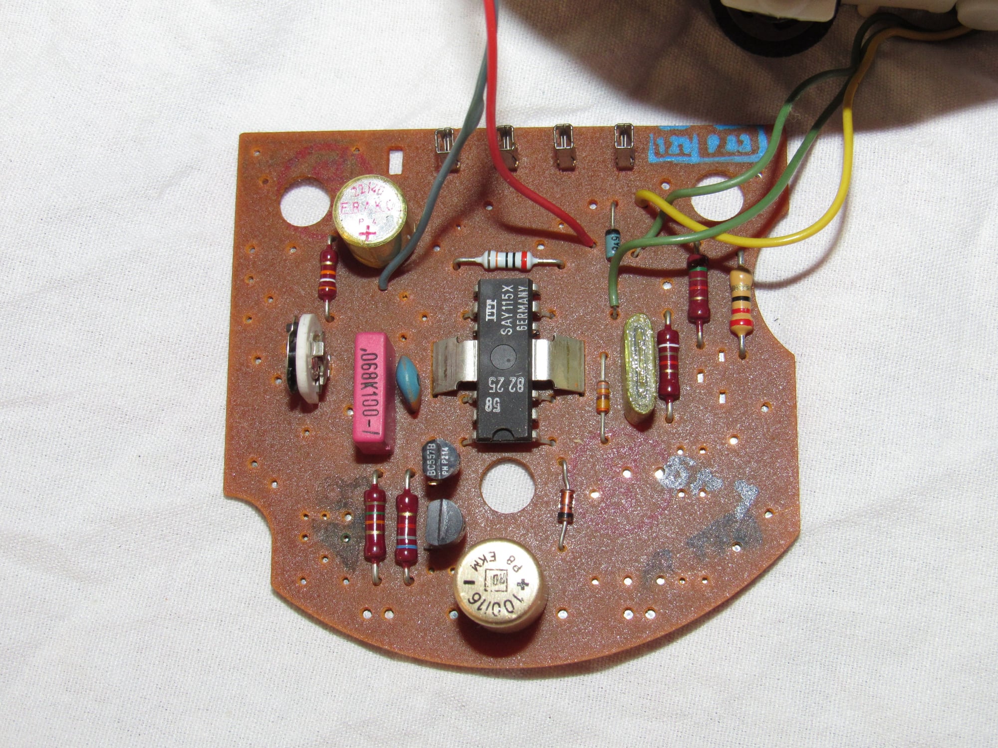
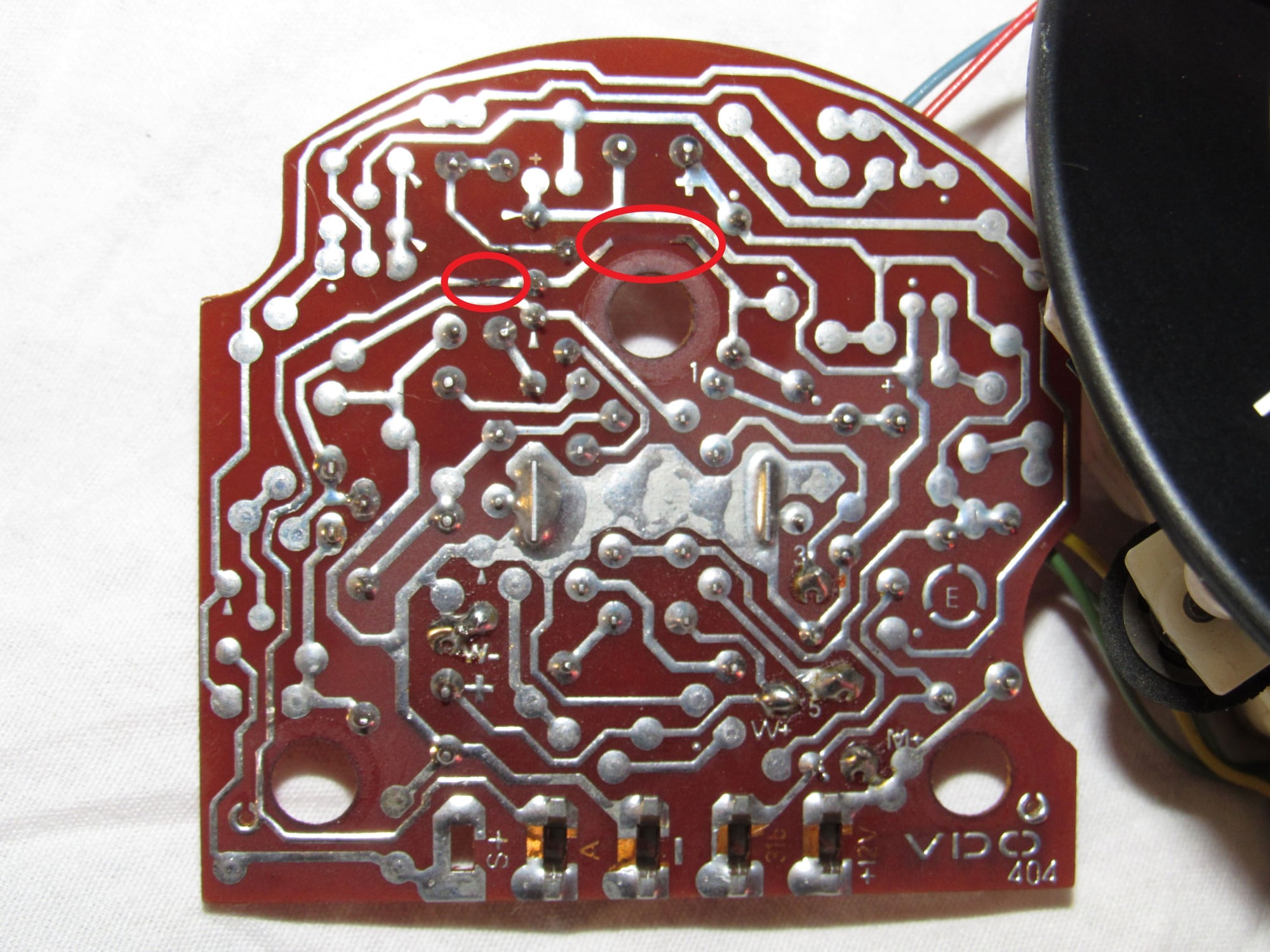
While searching for speedometer repair I came across some good information here. It seems somewhat common that the resistor and capacitors go bad. I decided to have one last look and my components look ok but I found my problem on the board itself. One of the traces is burnt through in two places. The trace comes from the "A" socket and I don't know what its function is but following it out to the edge connector of the circuit foil appears to be labelled TDM.GEB.
I received my rebuilt speedometer with a newer style control board and it still does not work. I borrowed a known working speedometer and it does not work either. I am measuring 8.08v (right or wrong) signal output from the edge connectors all the way out to the connector in the spare wheel well (no voltage drop). The way it works is a little different to what I thought. When the magnets on the differential passes near the speedo pickup sensor it closes a connection to ground, so the effect should be a pulsing of 8v to 0v repeating. There are eight magnets on the differential. I think I should be getting eight pulses per revolution of a wheel but I am only getting two or three. My speedometer slowly died after my gearbox swap and I am now beginning to suspect the magnet carrier. Has anyone heard of magnets falling out or anything weird?

 03-25-2012, 12:23 PM