
84 FUEL TANK REMOVAL PROCEDURE w/PICS
 01-07-2011, 02:08 PM
#1
Rennlist Member
Thread Starter
Join Date: Sep 2007
Location: Ridgecrest, California
Posts: 1,363
Likes: 0
Received 143 Likes
on
28 Posts
1984 FUEL TANK REMOVAL AND REPLACEMENT PROCEDURE
Here’s a step-by-step pictorial guide to removing and re-installing the fuel tank on a 1984 928. Although, I believe the steps in this procedure will apply to most 928 fuel tanks from 1980 on. I consider myself a Newbie at many of the 928 repairs and offer this detailed write up for my fellow Newbies that would like to try this procedure themselves. WARNING: this is a detailed write up with approximately 115 pictures.
First, some background that may aid in trouble shooting. California (the 1984) had developed a fuel leak at the fuel tank. It all started about a year ago on my last cross-country drive in California. After I had filled up with gas in Maryland for the return trip to California, I noticed a small drip of gasoline dripping from the bottom of the fuel tank when I got back to the hotel. Since I was leaving in the morning for the 3-day trip back, I had no time, tools or facility to look into the problem or fix it. So, I decided to chance it and press on with the plans to return home. On the way home, I checked for leaking gas whenever I stopped but didn’t see any. In fact, the rest of the way home I did not see any more leaks. Which seemed odd to have an intermittent fuel leak at the fuel tank.
After returning home to California and driving the 84 as I normally do, the leak returned with more regularity. I assumed the leak may have been coming from the bottom of the tank somewhere so I was puzzled why it was not leaking all the time. I did some more driving and observing until one day a new clue revealed itself. I had just finished filling the tank and topped it off nice and full. I had gone into the food mart at the station to get some nutritional provisions (Chips, Mountain Dew and Snowballs), when I see the leak again from under the tank but more than a few drops. Being away from home with no way to lift the car and find out where the leak was coming from, I decided to push onward once again. This time when I got home, I put the car on jack stands and had a look at the tank. Of course it was dry again so I could not see for sure where the leak was coming from but I could tell there were stains up high on the tank indicating the leak was not at the bottom of the tank but rather somewhere at the top. I checked the fuel level sending unit nut on top of the fuel tank and fuel return hose connection at the top of the tank but both were dry. Subsequently, I noticed I could produce fuel leaks on command every time I filled up. However, when I did not completely fill the tank, No Leaks!
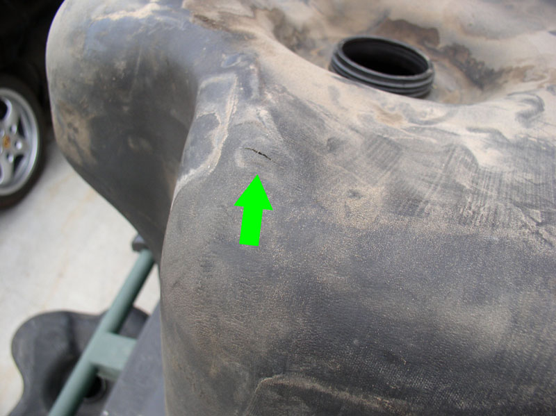
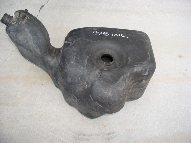
So, I went to the local gas station and filled it up and topped it off nice and full. I left the top of the fuel tank exposed in the hatch area so I could observe any leaks. Nothing at the fuel level sending unit nut or fuel return hose. However, gas was leaking at the bottom of the fuel tank again. I drove it home and put it on jack stands and had a look under the tank. Sure enough, the forward and left side (next to the battery box) of the tank was wet with gasoline. I was going to have to remove the tank to locate the leak. I just got the tank out yesterday and found the culprit – a crack in the top of the fuel tank! I’m wondering how common that is! I suspected I may have a defective tank so as a precaution, I had already ordered a used fuel tank from 928 Intl and picked it up during their Excellent � price sale last month – SO GLAD I DID! Here’s a pic of my defective tank at the crack:
PARTS-TOOLS-PREPARATION
For this job, I used the following parts:
1. Used fuel tank from 928 Intl.
Optional Parts to consider replacing while you’re in there (Using the PET Diagrams):
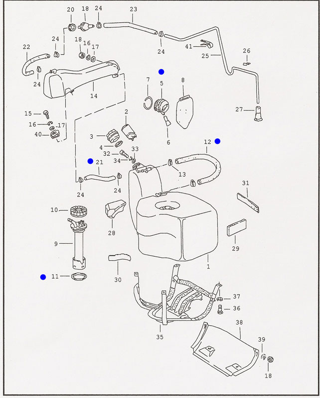
From the fuel tank diagram pictured below for an ‘84, inspect and consider replacing the item numbers with a BLUE dot next to them:
Item #5: Fuel filler grommet (928.201.333.02)
Item #11: Tank gauge gasket (928.201.327.02)
Item #12: Fuel tank vent hose (928.201.194.03)
Item #21: Vent hose (no part number but 250mm in length)
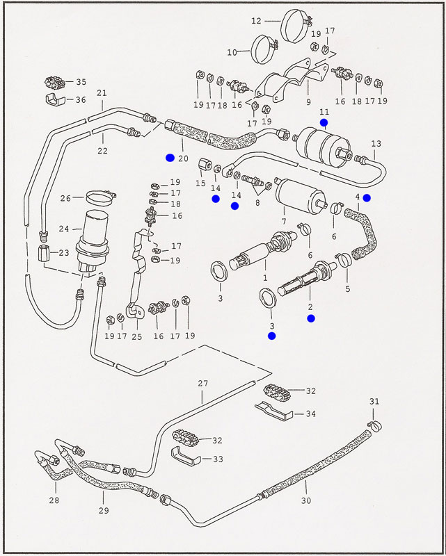
From the fuel pump diagram pictured below for an ‘84, inspect and consider replacing the item numbers with a BLUE dot next to them:
Item #2: In tank fuel filter (928.201.081.04)
Item #3: In tank fuel filter sealing ring (928.201.187.02)
Item #4: Fuel hose from tank to fuel pump (928.356.550.05)
Item #11: External fuel filter (928.110.253.06)
Item #14: Sealing rings (900.123.005.20)
Item #20: Fuel hose aft of external fuel filter (928.356.053.01)
TOOLS
There weren’t any special or custom tools required for this job. However, I did use Porken’s lift bars and the HF 6-Ton jack stands to lift the car high enough to gain clearance to remove the tank.
PREPARATION
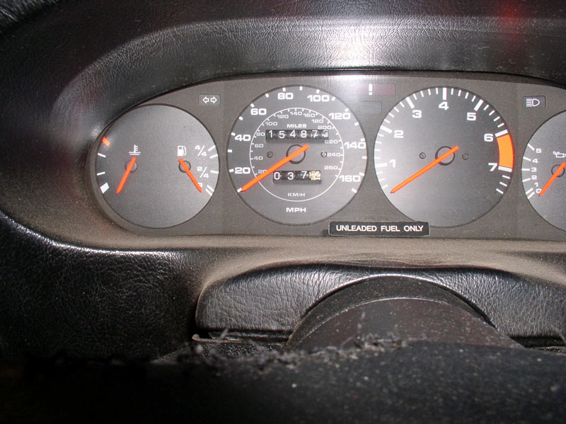
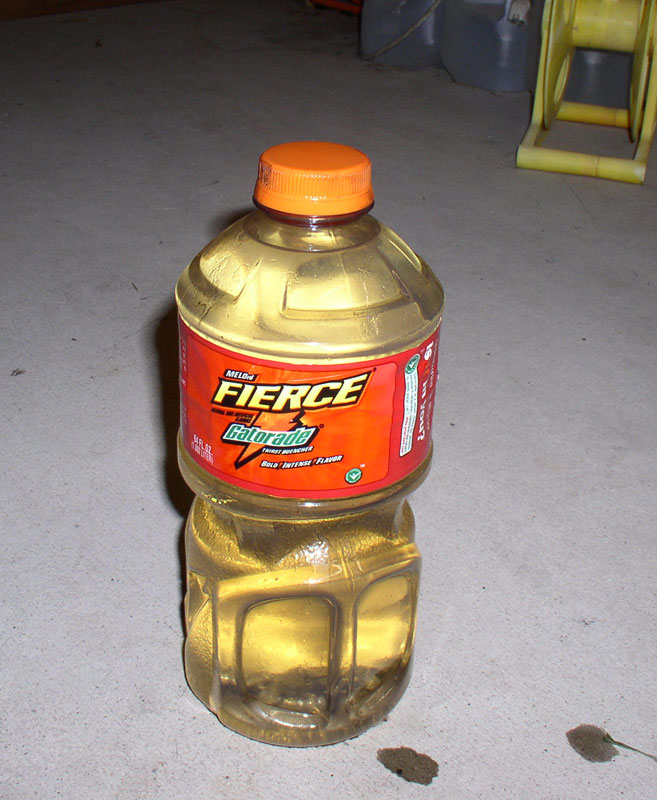
It is wise to empty the tank of gas as much as possible before starting this procedure as you will have to drain any left over fuel from the tank. I had been monitoring closely when the RED Low Fuel light would come on and how much gas the tank would take on a fill up to try and gauge how much fuel is left in the tank when the light comes on. Normally, when the light would just come on and I filled the tank, it would take about 18 gallons. Given the tank capacity is about 22 gallons, that means about 3-4 gallons should be remaining. I would hit the odometer reset button when the RED Low Fuel light would come on and monitor how many miles I could travel. I found the maximum distance I could comfortably drive without running out of gas was between 35 and 40 miles after the light came on (37 miles of city driving in this case).
When I retrieved the remaining fuel in the tank on this procedure, I recovered � gallon plus about 4 fluid oz.
I would not assume your car would do the same since the Low Fuel light may be calibrated differently but you can use the same method I did to make an educated guess how much you can drive safely to empty out most of the fuel.
Other preparation to consider is ordering parts ahead of time to minimize down time (if that’s important). If you have no record or knowledge of the Optional Parts listed previously being replaced, I would recommend ordering the parts and planning on replacing them when you have the tank out. The rubber parts on the fuel system are critical for safety and reliability and given the age of these cars it’s better to be safe than on fire!
FUEL TANK REMOVAL
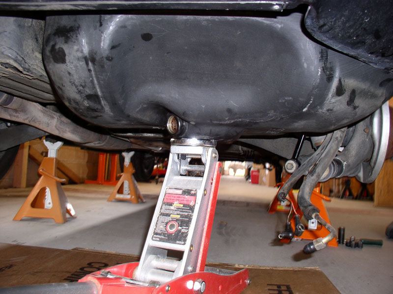
To start, I placed the 928 on lift bars and 6-Ton jack stands a maximum height I could with the floor jacks to allow maximum clearance for the tank removal.
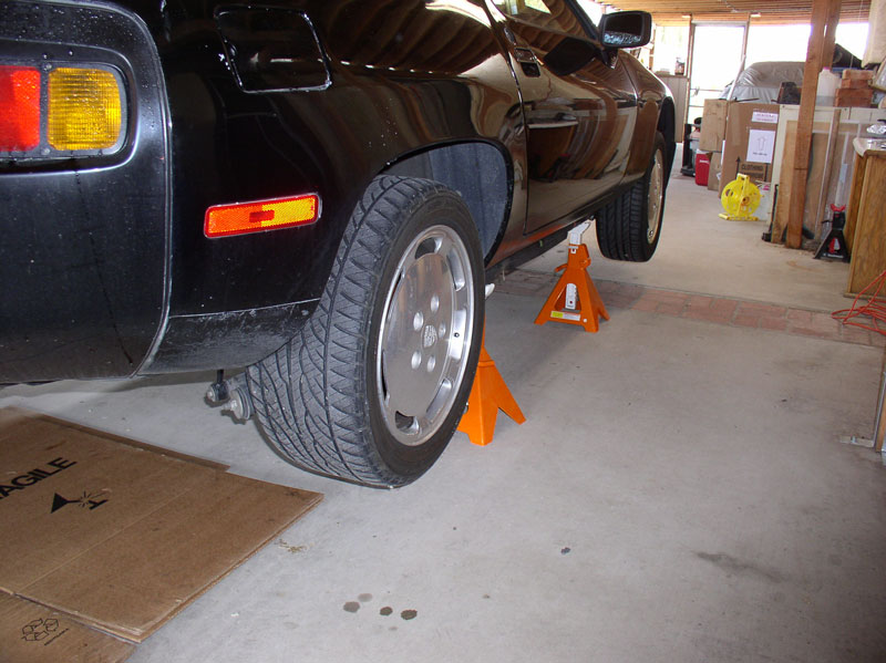
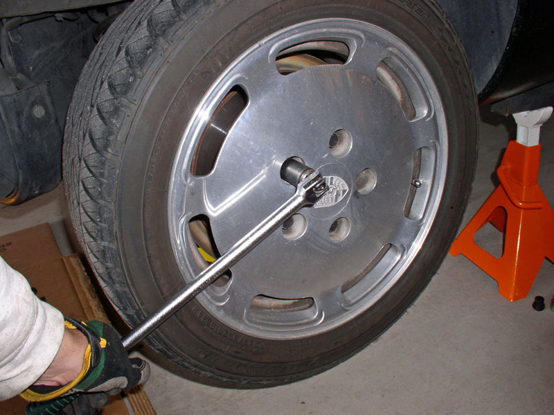
Remove the left rear wheel. I set the parking brake to keep the wheel from spinning. You could use an impact wrench or loosen the lug nuts while the car is on the ground.
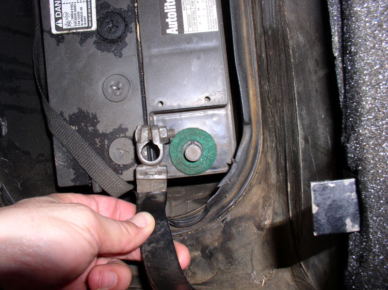
IMPORTANT: Disconnect the negative battery cable. Fire is nice to have in the winter cold months unless it’s you or your 928 that’s on fire!
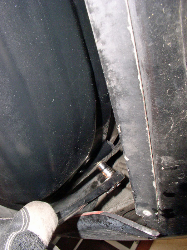
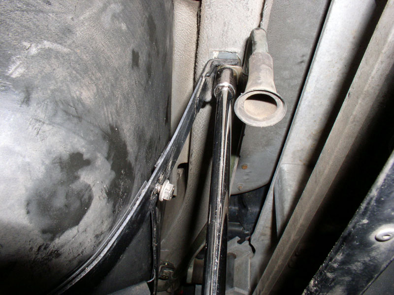
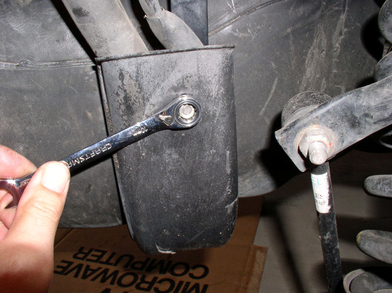
Remove the 10mm nuts that secure the fuel pump cover plate to the tank straps. There is one near the fuel vapor vent port pictured here.
And the other one at the other side of the tank near the rear bumper shock.
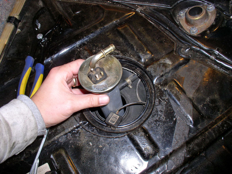
Pull the cover off the studs and pull the cover rearward to remove.
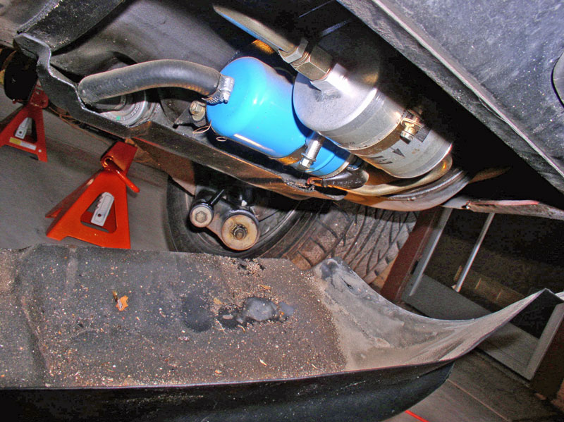
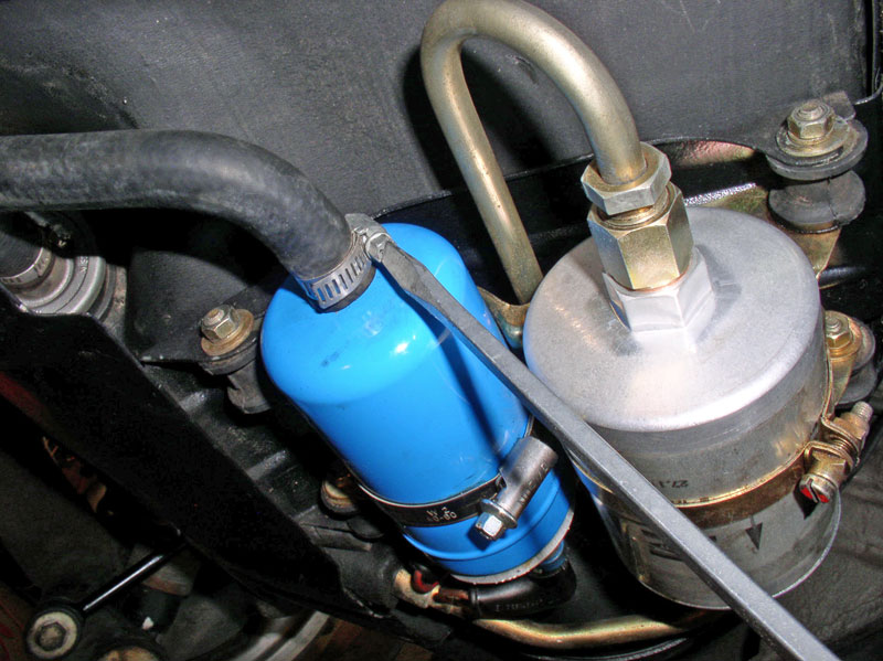
On the ’84, you will see the fuel pump (blue) and external fuel filter exposed.
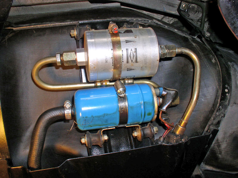
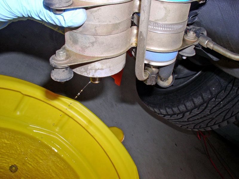
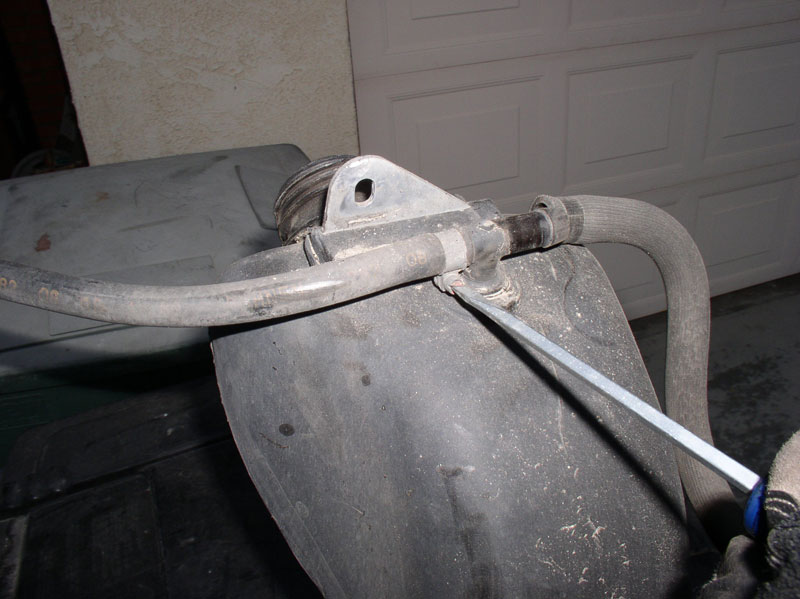
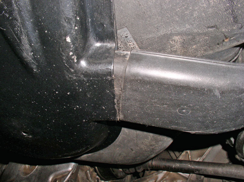
Drain the remaining fuel from the tank by loosening the clamp at the rubber hose coming from the fuel tank as shown below.
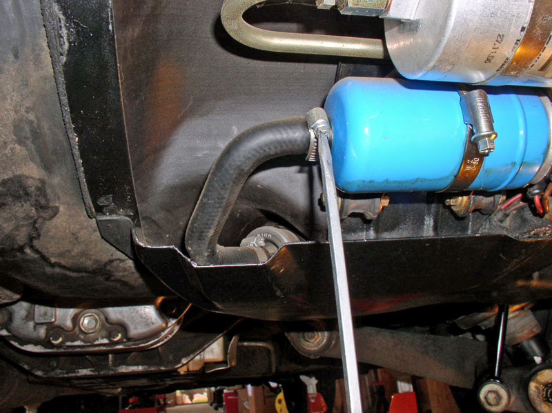
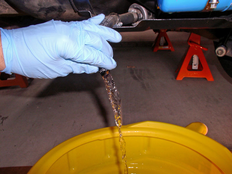
Place a suitable container for catching the fuel below the hose and pull the hose from the fuel pump and direct the fuel to the container.
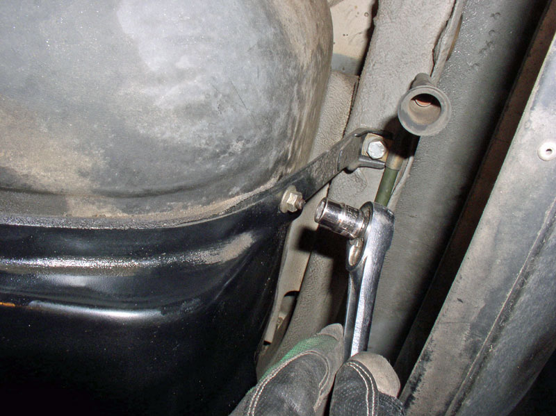
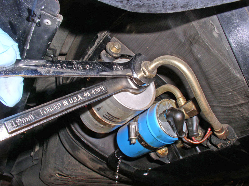
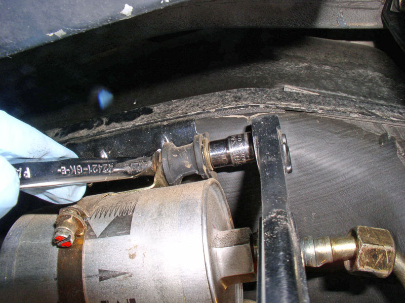
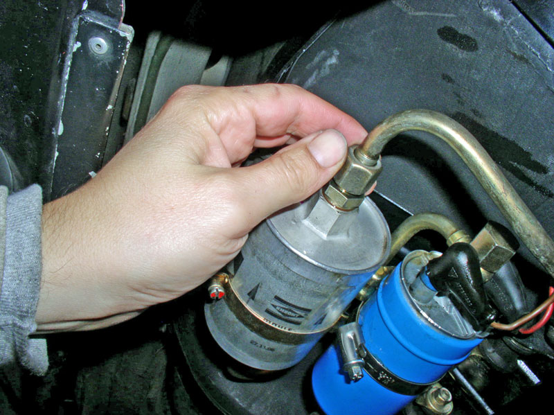
Disconnect the hard fuel line from the “Exit” end of the external fuel filter. It takes a 19mm wrench to loosen the nut and a 19mm wrench to counter hold the nut on the filter side.
Continued.....
Here’s a step-by-step pictorial guide to removing and re-installing the fuel tank on a 1984 928. Although, I believe the steps in this procedure will apply to most 928 fuel tanks from 1980 on. I consider myself a Newbie at many of the 928 repairs and offer this detailed write up for my fellow Newbies that would like to try this procedure themselves. WARNING: this is a detailed write up with approximately 115 pictures.
First, some background that may aid in trouble shooting. California (the 1984) had developed a fuel leak at the fuel tank. It all started about a year ago on my last cross-country drive in California. After I had filled up with gas in Maryland for the return trip to California, I noticed a small drip of gasoline dripping from the bottom of the fuel tank when I got back to the hotel. Since I was leaving in the morning for the 3-day trip back, I had no time, tools or facility to look into the problem or fix it. So, I decided to chance it and press on with the plans to return home. On the way home, I checked for leaking gas whenever I stopped but didn’t see any. In fact, the rest of the way home I did not see any more leaks. Which seemed odd to have an intermittent fuel leak at the fuel tank.
After returning home to California and driving the 84 as I normally do, the leak returned with more regularity. I assumed the leak may have been coming from the bottom of the tank somewhere so I was puzzled why it was not leaking all the time. I did some more driving and observing until one day a new clue revealed itself. I had just finished filling the tank and topped it off nice and full. I had gone into the food mart at the station to get some nutritional provisions (Chips, Mountain Dew and Snowballs), when I see the leak again from under the tank but more than a few drops. Being away from home with no way to lift the car and find out where the leak was coming from, I decided to push onward once again. This time when I got home, I put the car on jack stands and had a look at the tank. Of course it was dry again so I could not see for sure where the leak was coming from but I could tell there were stains up high on the tank indicating the leak was not at the bottom of the tank but rather somewhere at the top. I checked the fuel level sending unit nut on top of the fuel tank and fuel return hose connection at the top of the tank but both were dry. Subsequently, I noticed I could produce fuel leaks on command every time I filled up. However, when I did not completely fill the tank, No Leaks!
So, I went to the local gas station and filled it up and topped it off nice and full. I left the top of the fuel tank exposed in the hatch area so I could observe any leaks. Nothing at the fuel level sending unit nut or fuel return hose. However, gas was leaking at the bottom of the fuel tank again. I drove it home and put it on jack stands and had a look under the tank. Sure enough, the forward and left side (next to the battery box) of the tank was wet with gasoline. I was going to have to remove the tank to locate the leak. I just got the tank out yesterday and found the culprit – a crack in the top of the fuel tank! I’m wondering how common that is! I suspected I may have a defective tank so as a precaution, I had already ordered a used fuel tank from 928 Intl and picked it up during their Excellent � price sale last month – SO GLAD I DID! Here’s a pic of my defective tank at the crack:
PARTS-TOOLS-PREPARATION
For this job, I used the following parts:
1. Used fuel tank from 928 Intl.
Optional Parts to consider replacing while you’re in there (Using the PET Diagrams):
From the fuel tank diagram pictured below for an ‘84, inspect and consider replacing the item numbers with a BLUE dot next to them:
Item #5: Fuel filler grommet (928.201.333.02)
Item #11: Tank gauge gasket (928.201.327.02)
Item #12: Fuel tank vent hose (928.201.194.03)
Item #21: Vent hose (no part number but 250mm in length)
From the fuel pump diagram pictured below for an ‘84, inspect and consider replacing the item numbers with a BLUE dot next to them:
Item #2: In tank fuel filter (928.201.081.04)
Item #3: In tank fuel filter sealing ring (928.201.187.02)
Item #4: Fuel hose from tank to fuel pump (928.356.550.05)
Item #11: External fuel filter (928.110.253.06)
Item #14: Sealing rings (900.123.005.20)
Item #20: Fuel hose aft of external fuel filter (928.356.053.01)
TOOLS
There weren’t any special or custom tools required for this job. However, I did use Porken’s lift bars and the HF 6-Ton jack stands to lift the car high enough to gain clearance to remove the tank.
PREPARATION
It is wise to empty the tank of gas as much as possible before starting this procedure as you will have to drain any left over fuel from the tank. I had been monitoring closely when the RED Low Fuel light would come on and how much gas the tank would take on a fill up to try and gauge how much fuel is left in the tank when the light comes on. Normally, when the light would just come on and I filled the tank, it would take about 18 gallons. Given the tank capacity is about 22 gallons, that means about 3-4 gallons should be remaining. I would hit the odometer reset button when the RED Low Fuel light would come on and monitor how many miles I could travel. I found the maximum distance I could comfortably drive without running out of gas was between 35 and 40 miles after the light came on (37 miles of city driving in this case).
When I retrieved the remaining fuel in the tank on this procedure, I recovered � gallon plus about 4 fluid oz.
I would not assume your car would do the same since the Low Fuel light may be calibrated differently but you can use the same method I did to make an educated guess how much you can drive safely to empty out most of the fuel.
Other preparation to consider is ordering parts ahead of time to minimize down time (if that’s important). If you have no record or knowledge of the Optional Parts listed previously being replaced, I would recommend ordering the parts and planning on replacing them when you have the tank out. The rubber parts on the fuel system are critical for safety and reliability and given the age of these cars it’s better to be safe than on fire!
FUEL TANK REMOVAL
To start, I placed the 928 on lift bars and 6-Ton jack stands a maximum height I could with the floor jacks to allow maximum clearance for the tank removal.
Remove the left rear wheel. I set the parking brake to keep the wheel from spinning. You could use an impact wrench or loosen the lug nuts while the car is on the ground.
IMPORTANT: Disconnect the negative battery cable. Fire is nice to have in the winter cold months unless it’s you or your 928 that’s on fire!
Remove the 10mm nuts that secure the fuel pump cover plate to the tank straps. There is one near the fuel vapor vent port pictured here.
And the other one at the other side of the tank near the rear bumper shock.
Pull the cover off the studs and pull the cover rearward to remove.
On the ’84, you will see the fuel pump (blue) and external fuel filter exposed.
Drain the remaining fuel from the tank by loosening the clamp at the rubber hose coming from the fuel tank as shown below.
Place a suitable container for catching the fuel below the hose and pull the hose from the fuel pump and direct the fuel to the container.
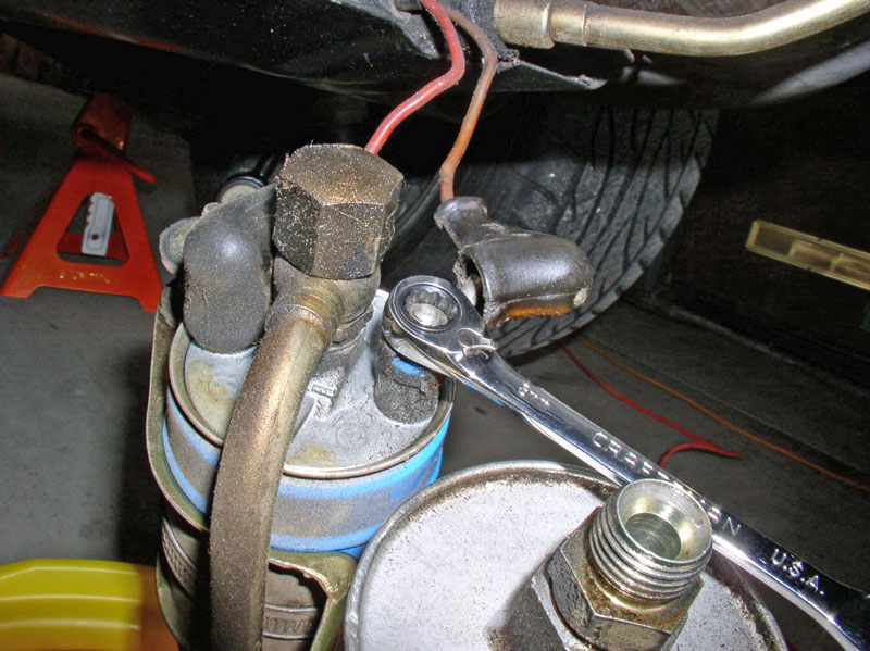
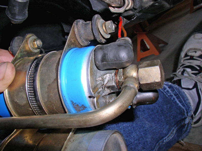
Disconnect the hard fuel line from the “Exit” end of the external fuel filter. It takes a 19mm wrench to loosen the nut and a 19mm wrench to counter hold the nut on the filter side.
Continued.....
Last edited by Dwayne; 01-08-2011 at 01:20 PM.
 01-07-2011, 02:15 PM
#2
Rennlist Member
Thread Starter
Join Date: Sep 2007
Location: Ridgecrest, California
Posts: 1,363
Likes: 0
Received 143 Likes
on
28 Posts
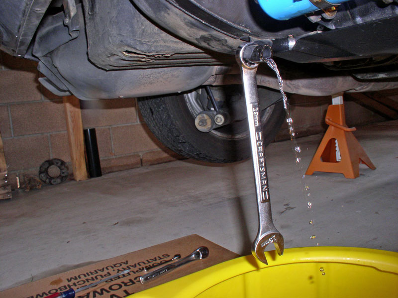
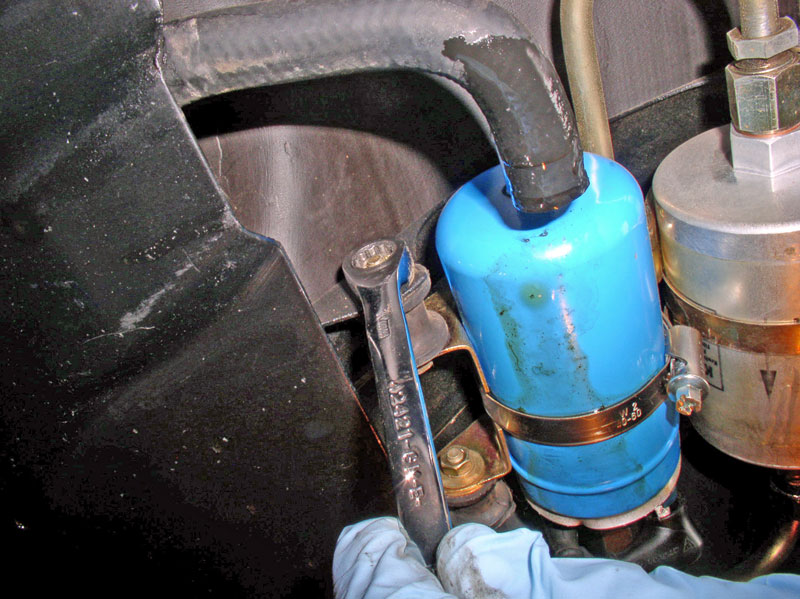
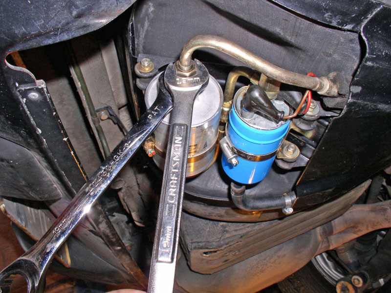
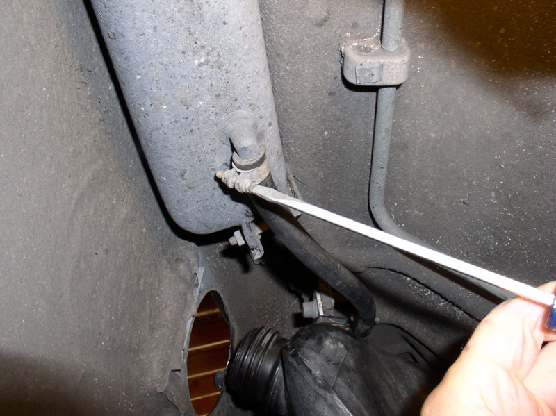
It may take some time for the fuel to empty as it dribbles out. I found it handy to hang my 19mm wrench on the hose to hold it in a downward angle to allow the fuel to escape out the hose rather than dribble back under the strap plate.
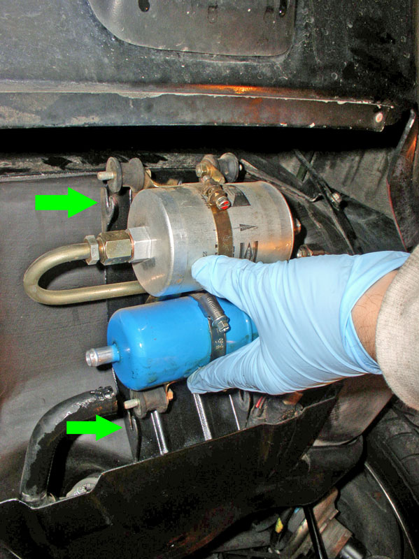
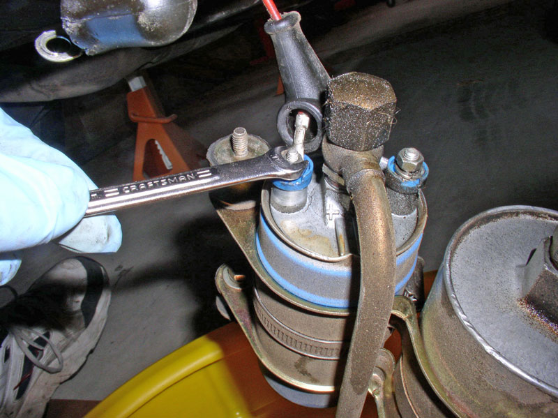
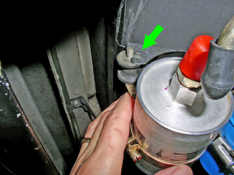
Remove the fuel pump and filter mounting bracket next. You will only need to remove the OUTWARD facing 10mm nuts. There are 4 of them � two on the right�.
�.and two on the left.
You will notice the bracket has slots that allow the bracket to slide on out when the OUTWARD nuts are removed as pictured below.
Tip the filter and pump to drain any residual fuel.
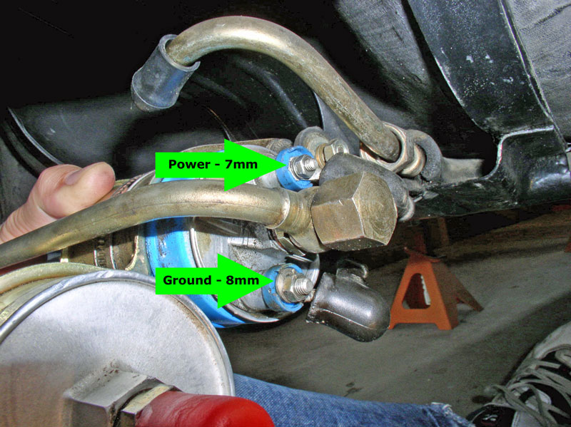
Remove the electrical wires from the fuel pump. The ground wire (brown) takes an 8mm wrench.
The power lead takes a 7mm wrench. This helps keep the wires from being attached to the wrong terminals.
The assembly should be fully detached at this point. Here�s what it should look like from the rear side exposing the bracket.
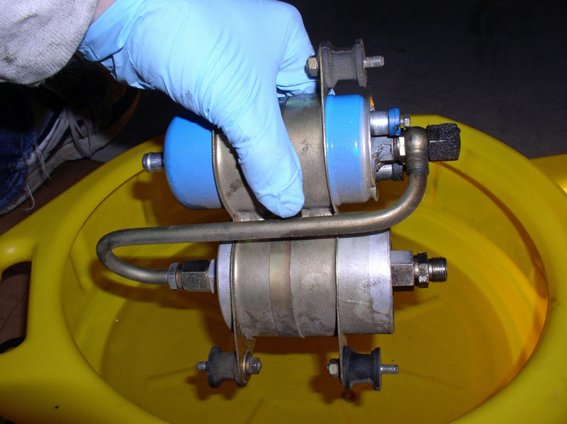
And the outward facing side.
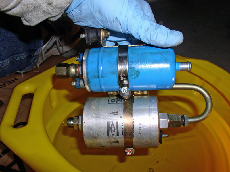
Cap the fuel filter side to prevent dirt from entering the filter unless you are replacing the filter. Also cap the exposed side of the fuel pump.
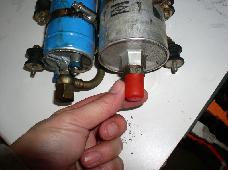
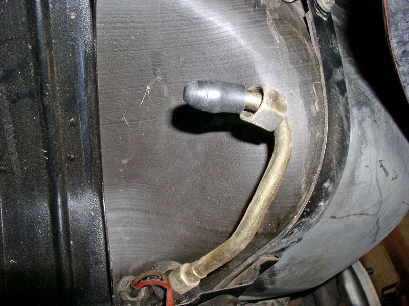
Also cap the hard fuel line at the �Exit� side of the fuel filter as shown.
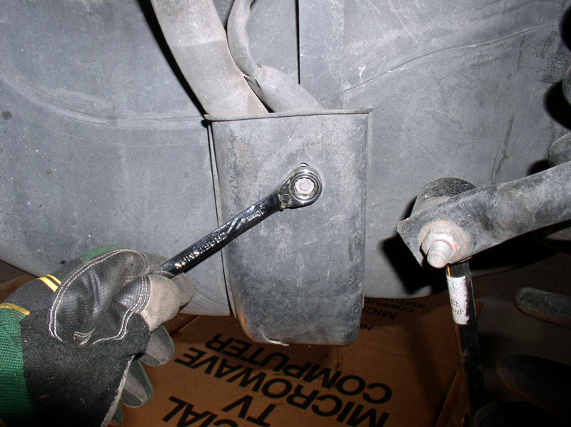
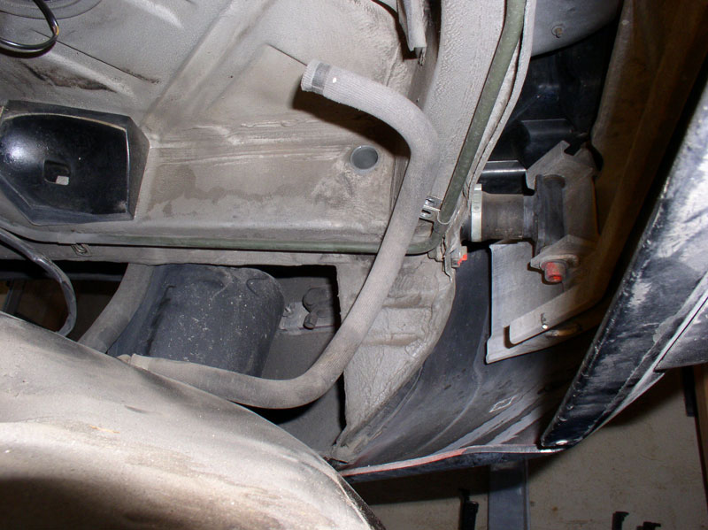
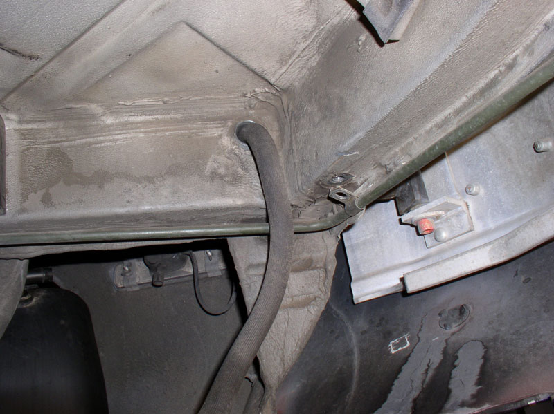
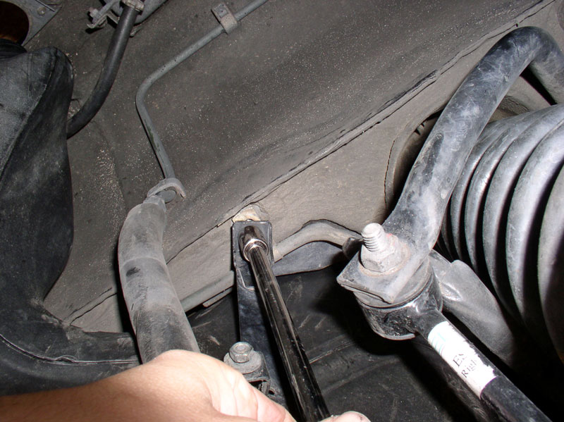
At the wheel well, remove the 10mm nut that secures the plastic cover over the wiring harness and fuel line.
Remove the cover.
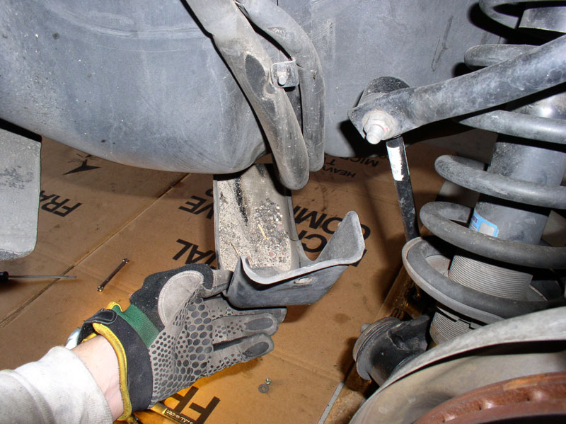
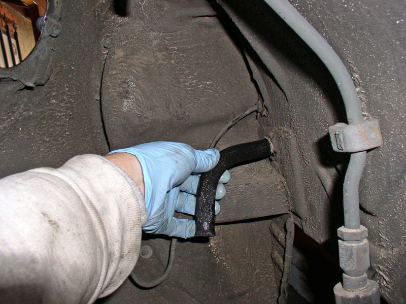
Also, loosen the clamp on the vent hose at the compensating tank.
And disconnect the hose.

Continued....
Remove the fuel pump and filter mounting bracket next. You will only need to remove the OUTWARD facing 10mm nuts. There are 4 of them � two on the right�.
�.and two on the left.
You will notice the bracket has slots that allow the bracket to slide on out when the OUTWARD nuts are removed as pictured below.
Tip the filter and pump to drain any residual fuel.
Remove the electrical wires from the fuel pump. The ground wire (brown) takes an 8mm wrench.
The power lead takes a 7mm wrench. This helps keep the wires from being attached to the wrong terminals.
The assembly should be fully detached at this point. Here�s what it should look like from the rear side exposing the bracket.
And the outward facing side.
Cap the fuel filter side to prevent dirt from entering the filter unless you are replacing the filter. Also cap the exposed side of the fuel pump.
Also cap the hard fuel line at the �Exit� side of the fuel filter as shown.
At the wheel well, remove the 10mm nut that secures the plastic cover over the wiring harness and fuel line.
Remove the cover.
Also, loosen the clamp on the vent hose at the compensating tank.
And disconnect the hose.
Continued....
01-07-2011, 02:23 PM
#3
Rennlist Member
Thread Starter
Join Date: Sep 2007
Location: Ridgecrest, California
Posts: 1,363
Likes: 0
Received 143 Likes
on
28 Posts
In the hatch area, remove the protective cover over the fuel level sending unit access port.
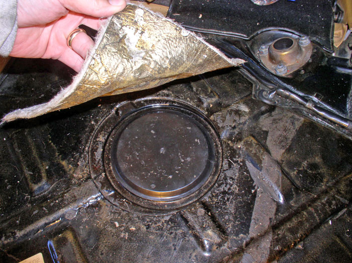
Remove the plastic lid.
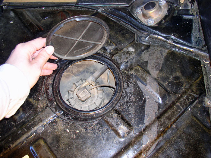
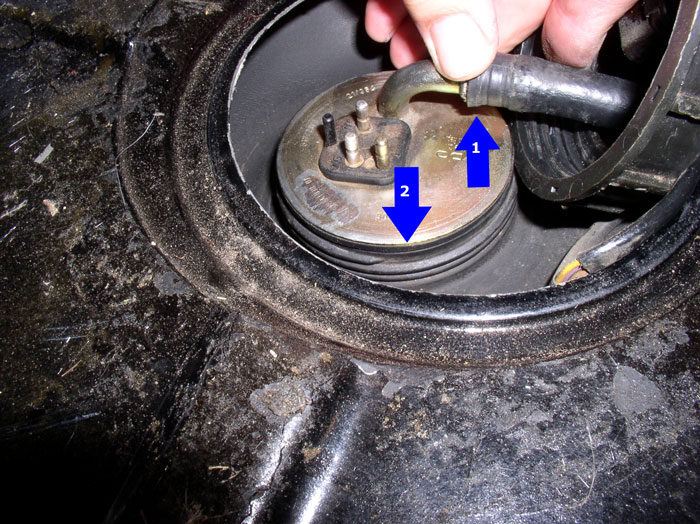
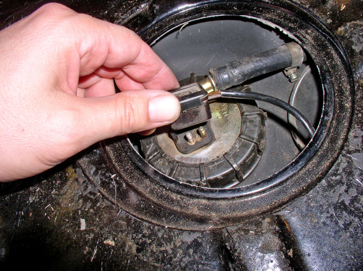
Unplug the wire connector to the fuel level sending unit. The plug is keyed so it will only go on one way.
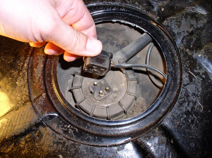
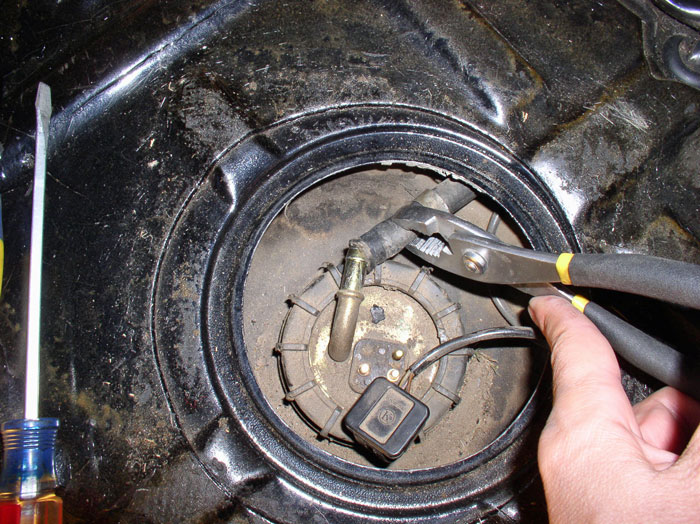
Loosen the fuel return hose clamp.
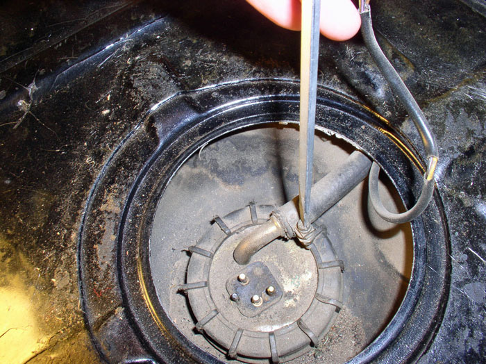
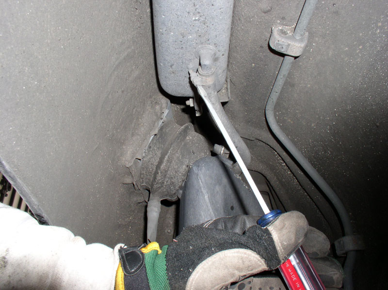
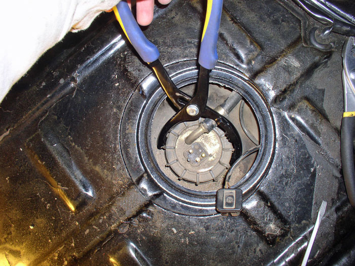
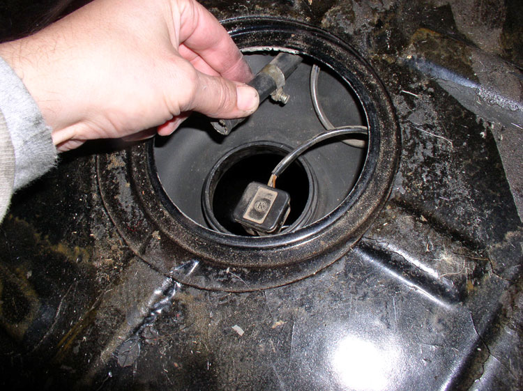
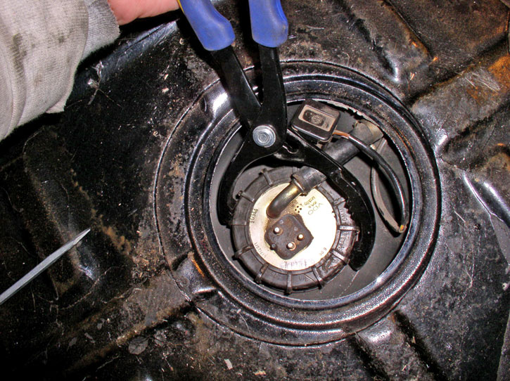
I used a pair of Oil Filter pliers to loosen the fuel level sending unit plastic nut.
With the fuel level sending unit loose enough to rotate, I found it�s easier to disconnect the fuel return hose from the unit.
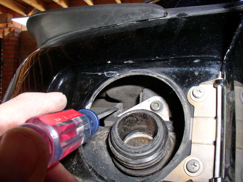
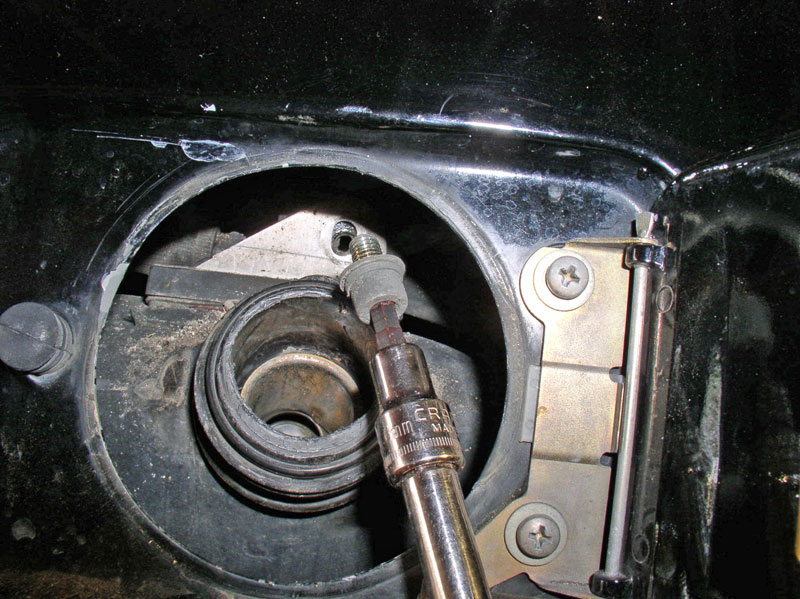
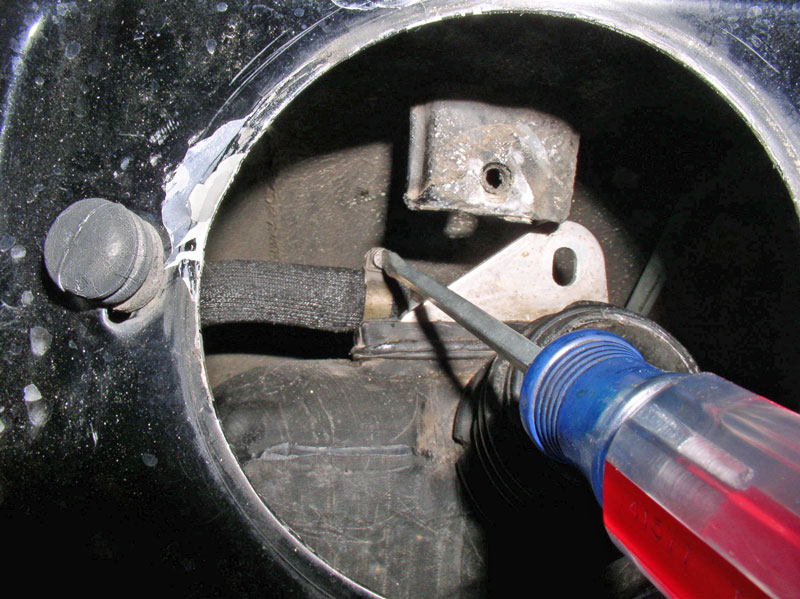
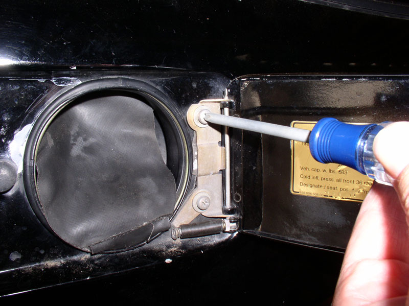
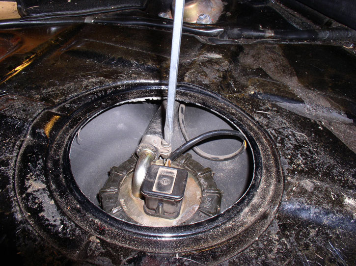
Using a screwdriver, carefully pry out the locking ring to the fuel filler grommet.
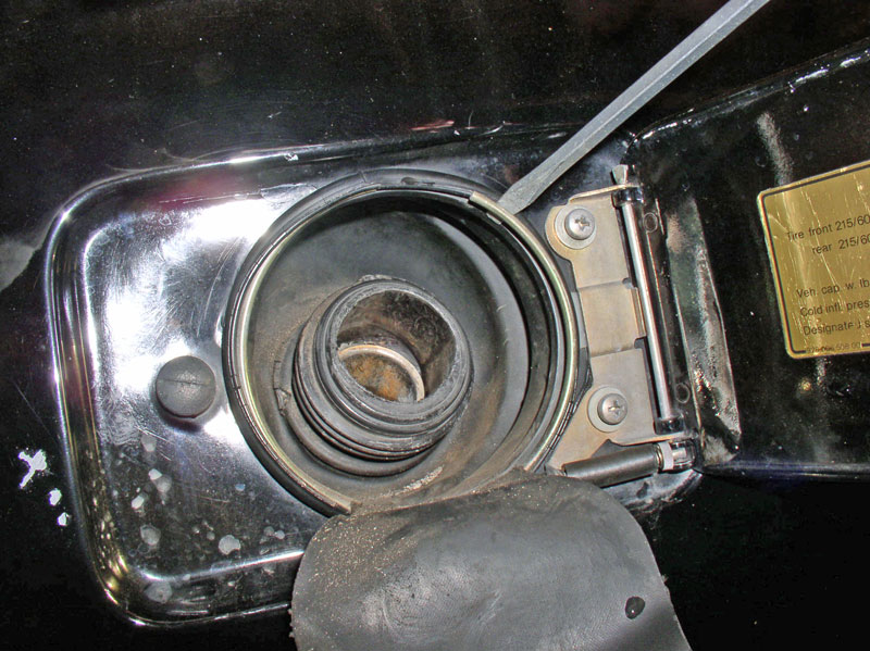
The ring should come out with the gas filler �flap� attached.
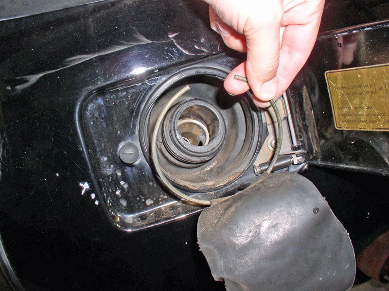
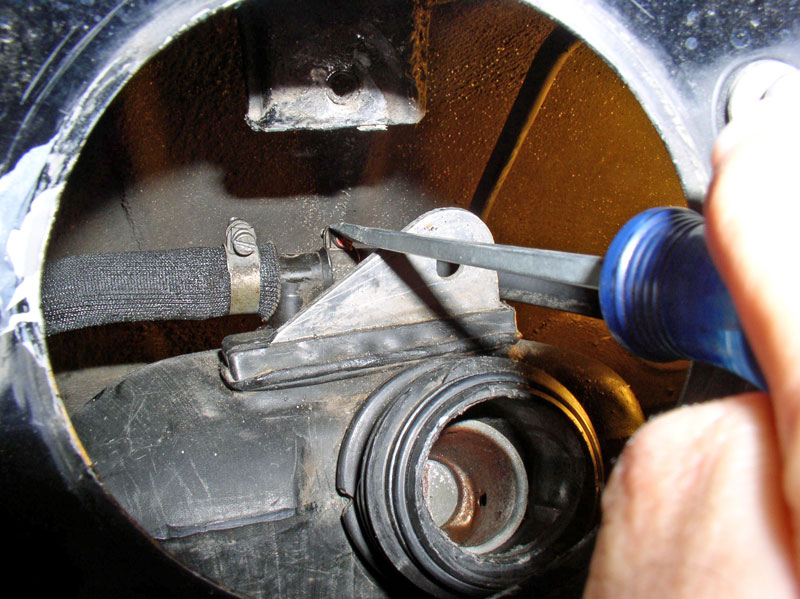
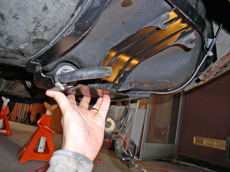
Remove the drain spigot attachment from underneath the fuel filler grommet.
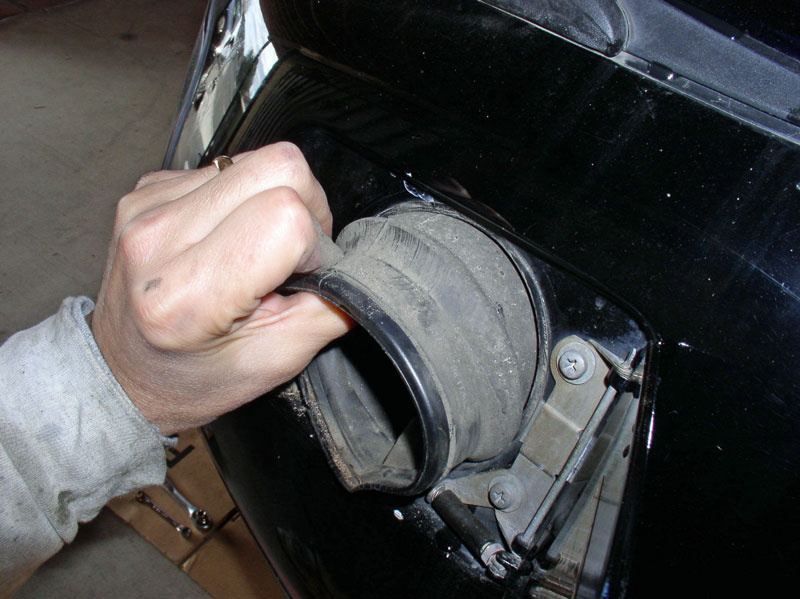
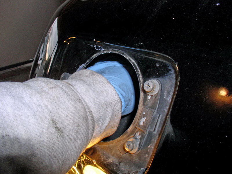
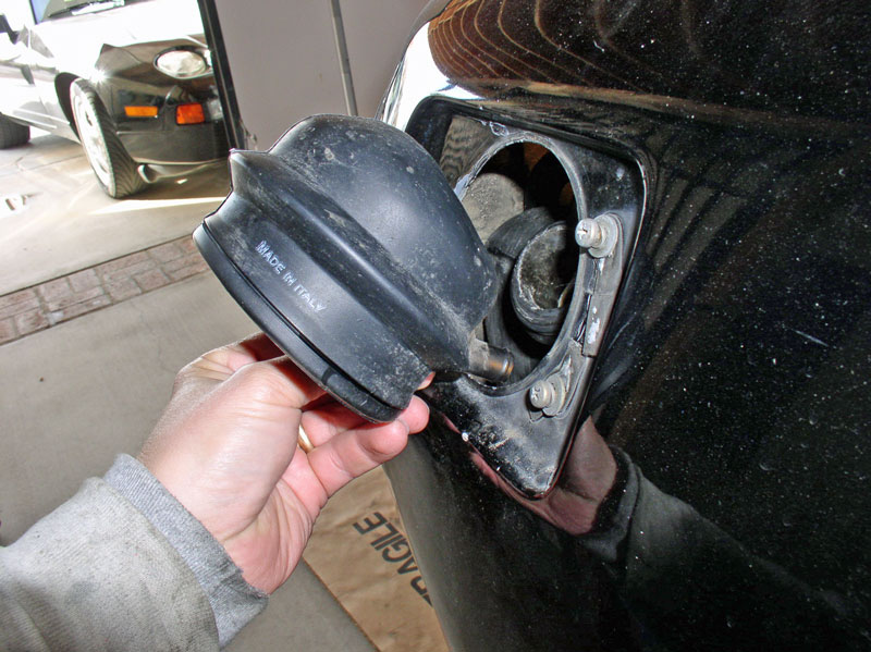
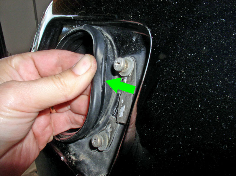
Pull out the fuel filler grommet while detaching it from the fuel tank filler opening. I found I could reach around the fender and help separate the grommet from the fuel tank with one hand while pulling on the grommet from the filler door (as pictured below) with the other hand.
Following this procedure leaves the vent hose intact vs cutting the hose (an option). The vent hose is routed through the body framing so the tank can not be removed unless the hose is disconnected or cut. If you are replacing the hose, cutting it may be the easier approach and cutting the hose will reduce the risk of breaking the plastic connectors on the fuel tank while you�re wrestling the hose off these connectors. When the grommet is removed, you will see the 6mm Allen head bolt that secures the fuel tank filler to the body of the car and you�ll notice the hose clamp for the larger vent hose to the left. Loosen the vent hose clamp and slide the clamp back. We won�t be disconnecting the hose yet. I found dropping the tank a few inches first provided enough room to get my hand in there to grasp the hose and disconnect it.
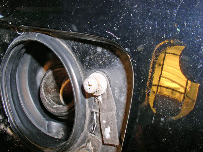
Remove the 6mm Allen head bolt.
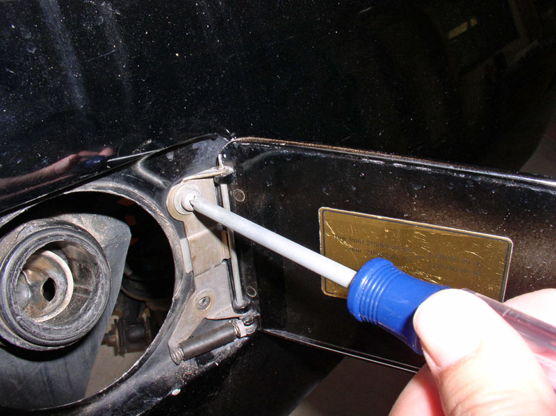
Although it was not entirely necessary, I decided to remove the fuel filler door to allow maximum access. It was easy since it involved only removing the 2 Phillips screws as shown.
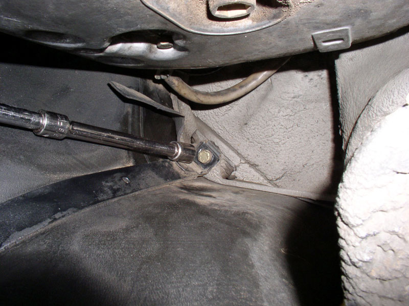
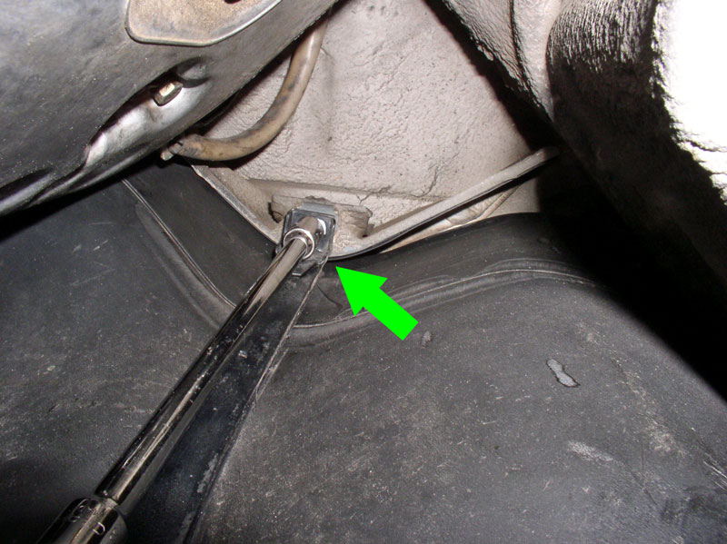
Next, remove the four 13mm fuel tank strap bolts. One is located at the rear near the vapor exit port as shown below.
The other rear bolt is located near the left rear bumper shock.
Continued....
Remove the plastic lid.
Unplug the wire connector to the fuel level sending unit. The plug is keyed so it will only go on one way.
Loosen the fuel return hose clamp.
I used a pair of Oil Filter pliers to loosen the fuel level sending unit plastic nut.
With the fuel level sending unit loose enough to rotate, I found it�s easier to disconnect the fuel return hose from the unit.
Using a screwdriver, carefully pry out the locking ring to the fuel filler grommet.
The ring should come out with the gas filler �flap� attached.
Remove the drain spigot attachment from underneath the fuel filler grommet.
Pull out the fuel filler grommet while detaching it from the fuel tank filler opening. I found I could reach around the fender and help separate the grommet from the fuel tank with one hand while pulling on the grommet from the filler door (as pictured below) with the other hand.
Following this procedure leaves the vent hose intact vs cutting the hose (an option). The vent hose is routed through the body framing so the tank can not be removed unless the hose is disconnected or cut. If you are replacing the hose, cutting it may be the easier approach and cutting the hose will reduce the risk of breaking the plastic connectors on the fuel tank while you�re wrestling the hose off these connectors. When the grommet is removed, you will see the 6mm Allen head bolt that secures the fuel tank filler to the body of the car and you�ll notice the hose clamp for the larger vent hose to the left. Loosen the vent hose clamp and slide the clamp back. We won�t be disconnecting the hose yet. I found dropping the tank a few inches first provided enough room to get my hand in there to grasp the hose and disconnect it.
Remove the 6mm Allen head bolt.
Although it was not entirely necessary, I decided to remove the fuel filler door to allow maximum access. It was easy since it involved only removing the 2 Phillips screws as shown.
Next, remove the four 13mm fuel tank strap bolts. One is located at the rear near the vapor exit port as shown below.
The other rear bolt is located near the left rear bumper shock.
Continued....
01-07-2011, 02:30 PM
#4
Rennlist Member
Thread Starter
Join Date: Sep 2007
Location: Ridgecrest, California
Posts: 1,363
Likes: 0
Received 143 Likes
on
28 Posts
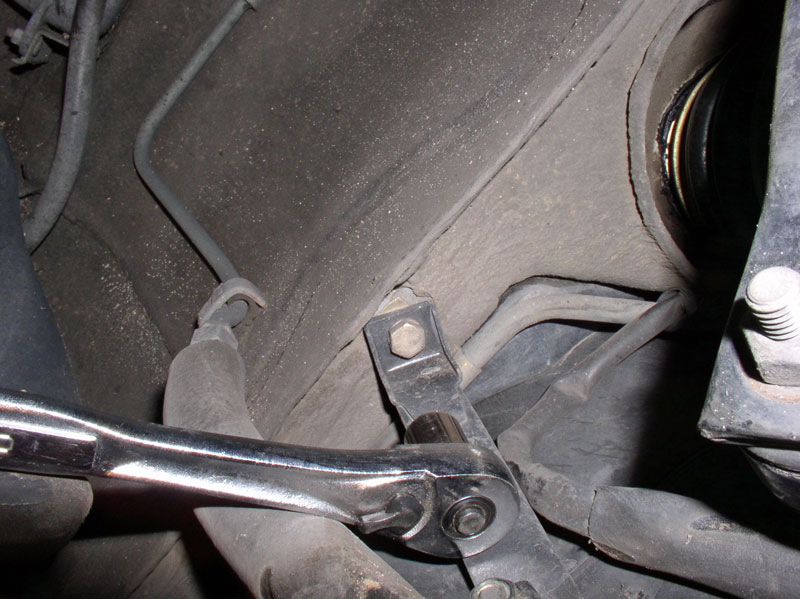
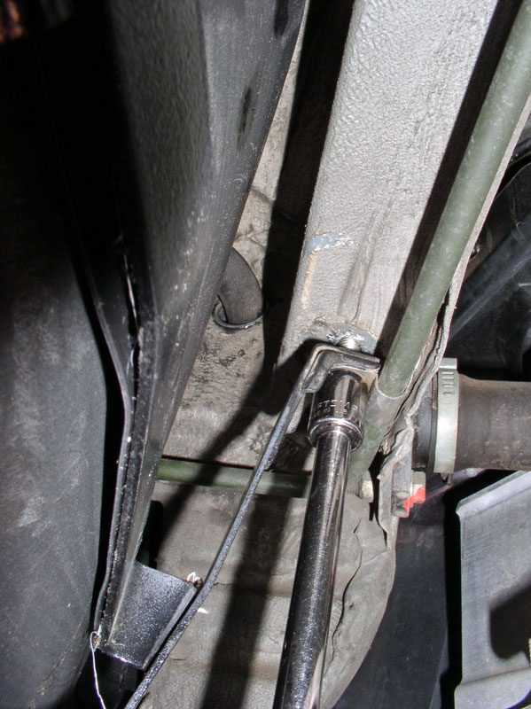
Another one on the forward side of the tank just in front of the transmission.
And the last one located at the rear wheel well near the rear shock.
With the 4 bolts removed the strap should pull down easily. The fuel tank is very light when all the fuel is emptied and the pumps, filter and brackets are removed so I did not need to support the tank when the strap was removed. It actually stayed in place.
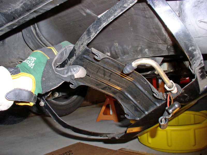
When the strap is down, you will need to pull the wiring harness and rubber fuel line out from under the strap shown below.
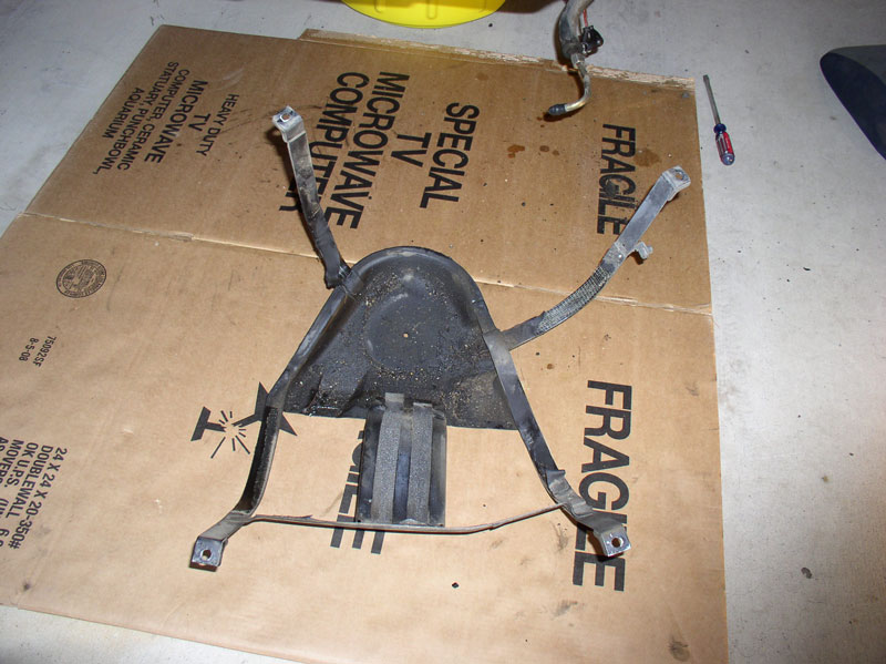
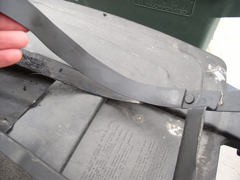
The strap should be fully disconnected now. Notice the strap has thin rubber padding installed on each leg and on the fuel pump/filter backing. If your padding is deteriorated, it can be replaced with similar foam padding with adhesive backing available at Home Depot or I heard you can use segments of a tire inner tube.
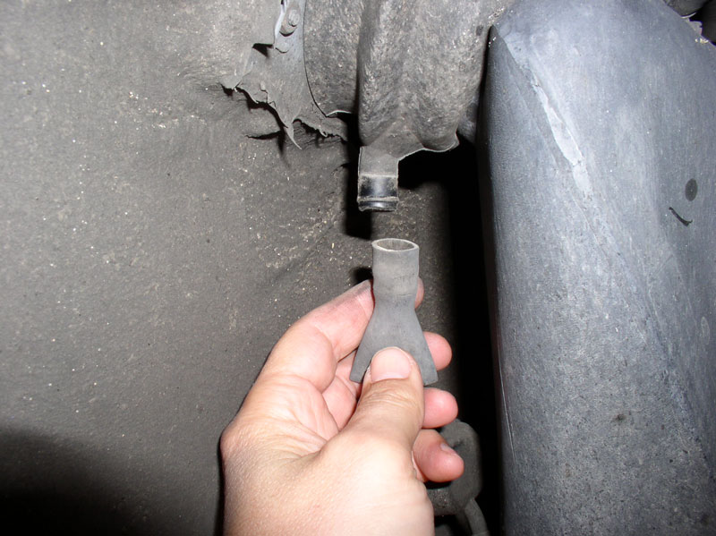
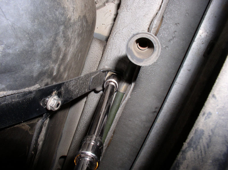
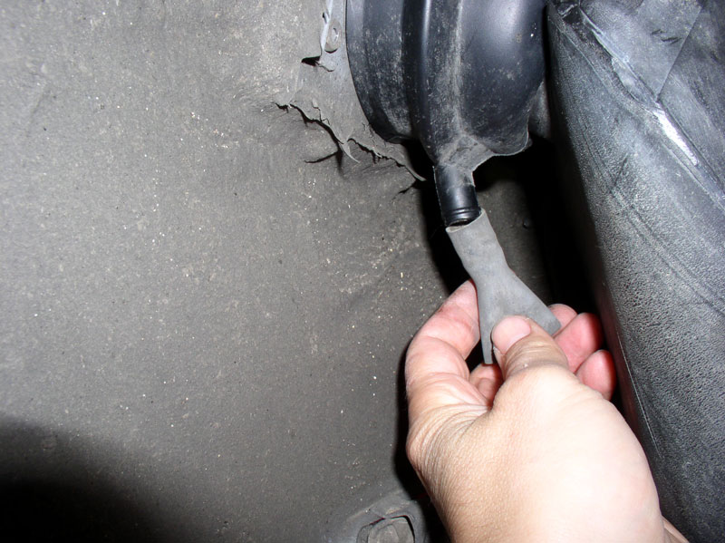
Next, pull down slightly on the tank and it should easily drop to one side. It will be hung up by the vent hose running through the body frame.
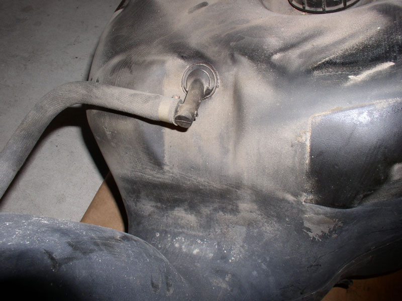
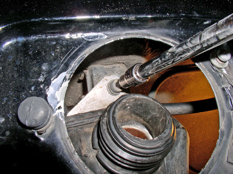
From the gas filler port, you should have good access to the vent hose connection.
I reached in and grasp the hose, twisted it to break it free and pulled and twisted to remove it.
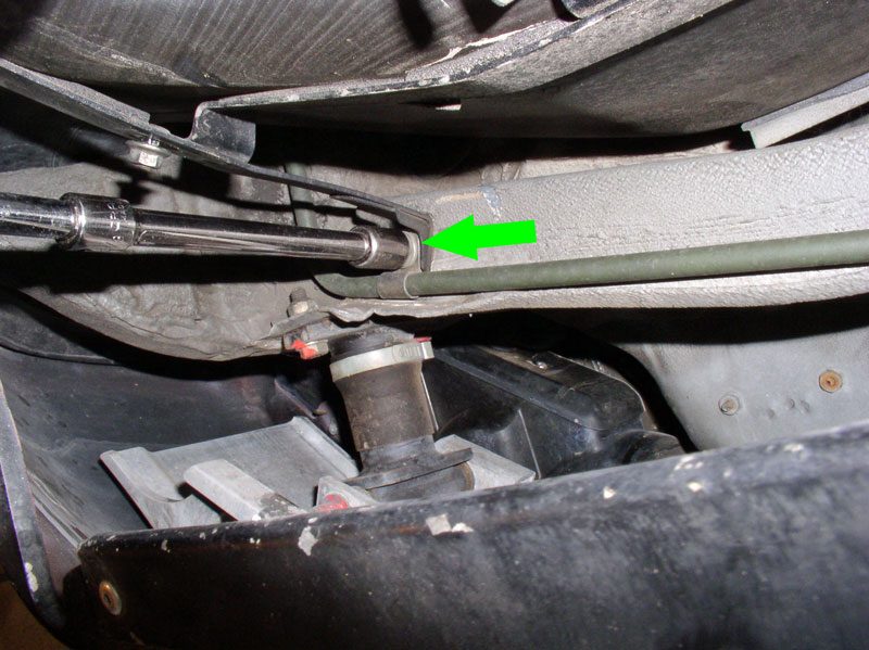
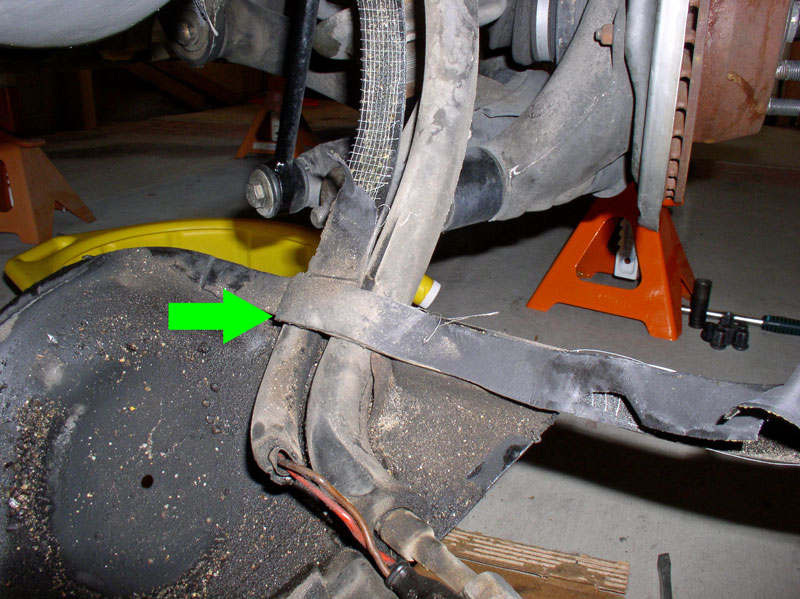
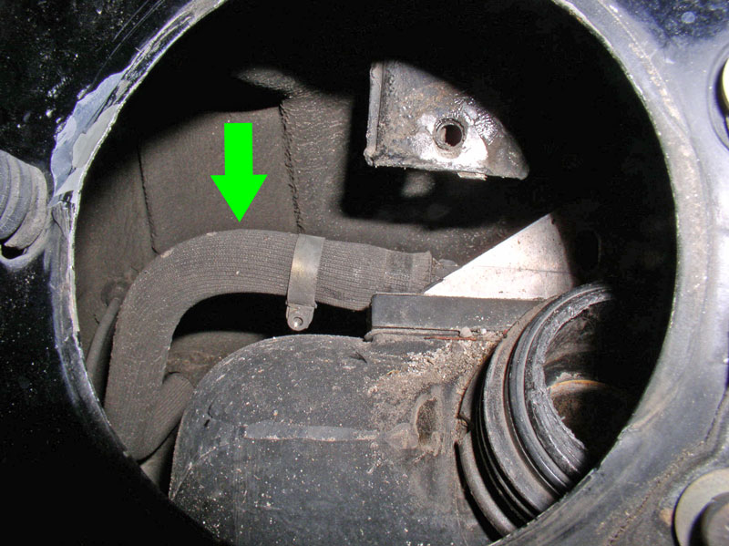
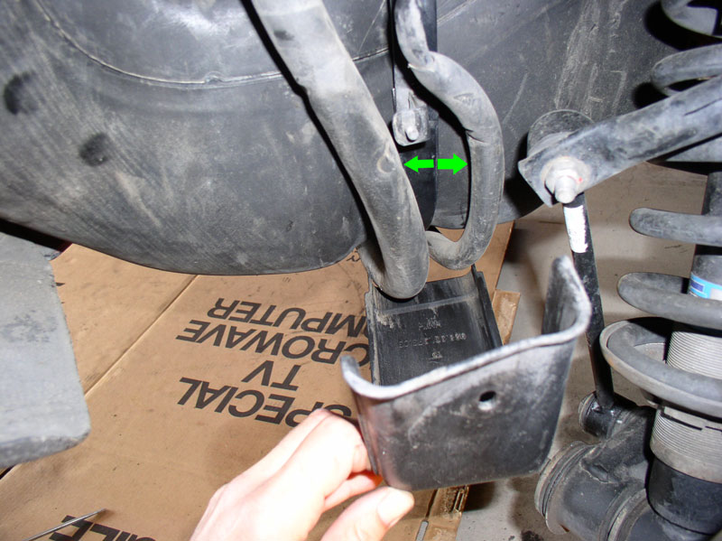
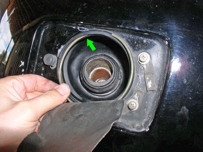
If you choose the �Cut the hose� option, you should be able to see the hose exposed while the tank is partially lowered. Use a pair of hose snips to cut the hose here at the green arrow.
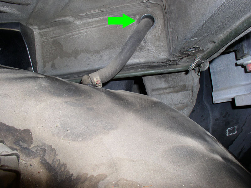
If you choose to save the hose, simply pull the hose through the body frame port.
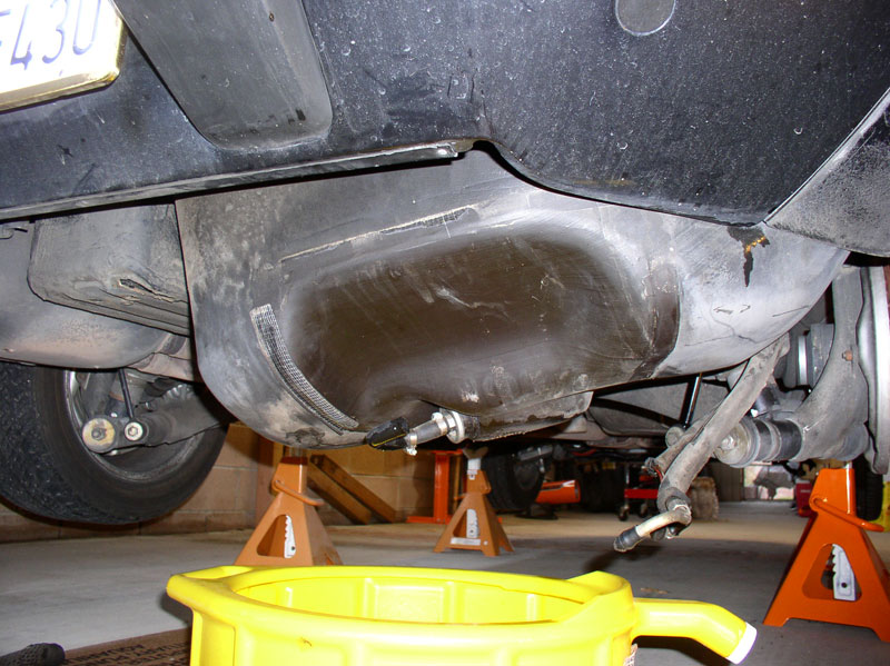
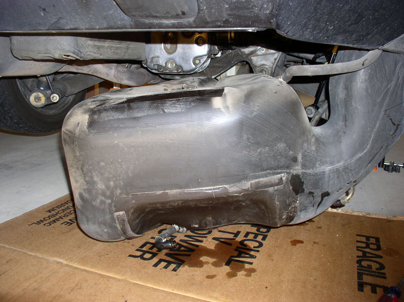
Continue lowering and maneuvering the tank down.
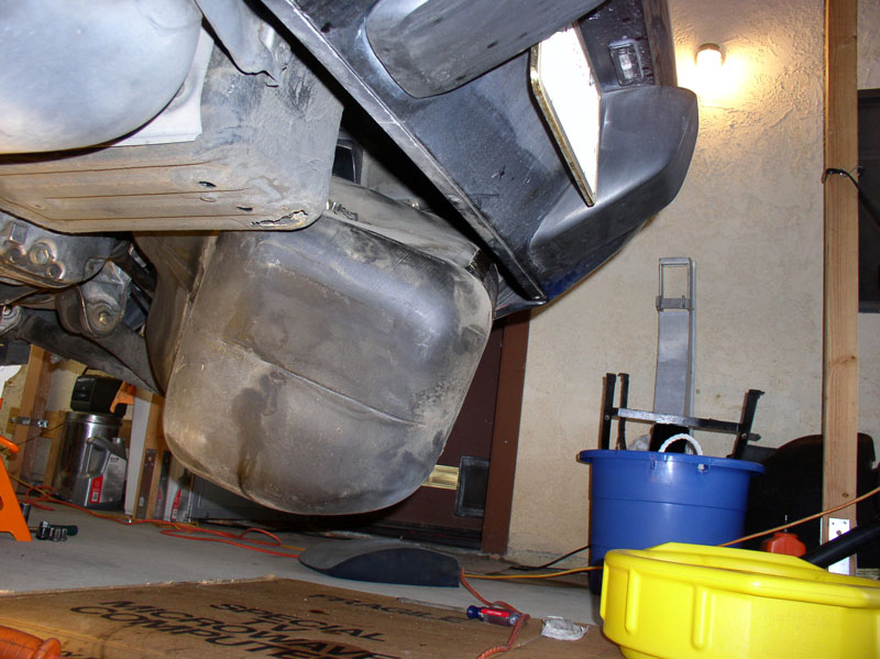
Until it is down and free from the body.
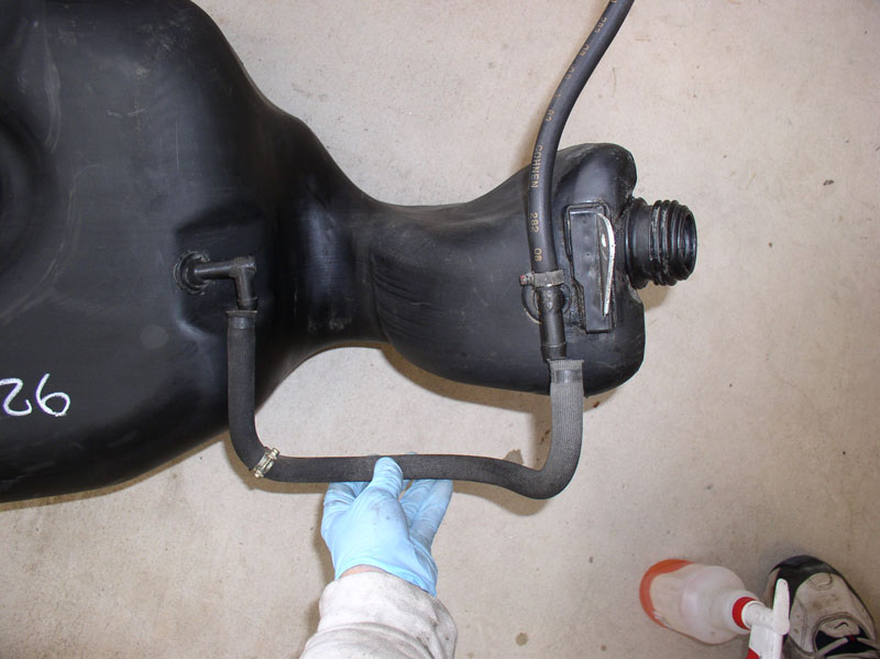
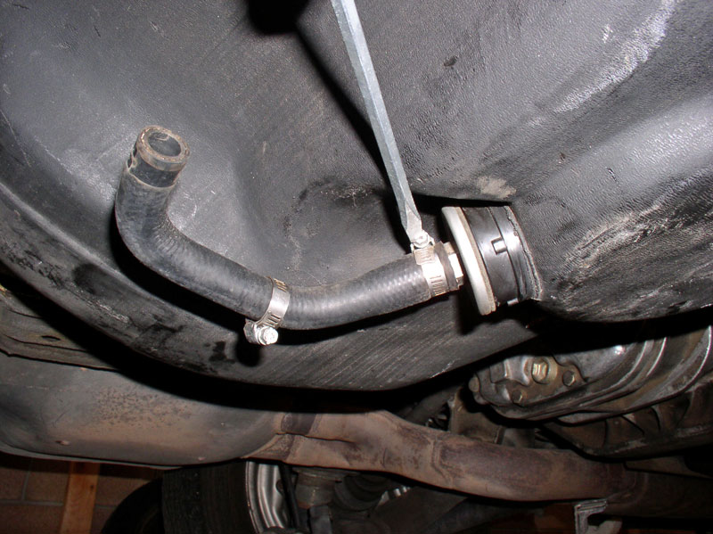
I was very anxious at this point to discover the source of the leak. I understand it is common for the vent hose pictured below to age, disintegrate and be the source of fuel leaks. Also the plastic connector at the tank may break or crack and be a source of leak. Mine was bone dry. In addition, when I observed gas coming down the outside of the tank, it wasn�t in this vicinity.
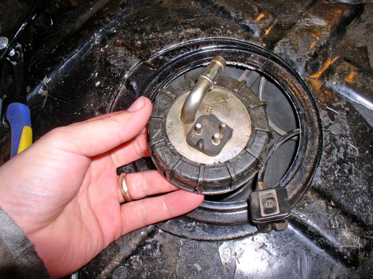
At the fuel level sender unit, I noticed staining but it was dry as well.
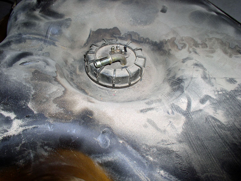
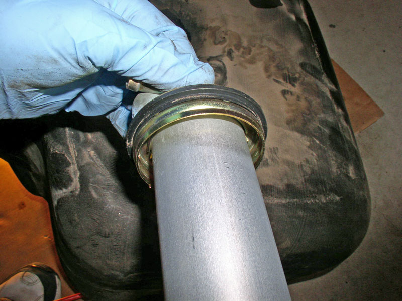
I finished removing the plastic nut and pulled the sending unit out and inspected the gasket. Looked great! I was pretty sure the gasket was not a problem because I did not see any fuel leaking around the gasket when I observed fuel was leaking at the bottom of the tank.
Continued....
And the last one located at the rear wheel well near the rear shock.
With the 4 bolts removed the strap should pull down easily. The fuel tank is very light when all the fuel is emptied and the pumps, filter and brackets are removed so I did not need to support the tank when the strap was removed. It actually stayed in place.
When the strap is down, you will need to pull the wiring harness and rubber fuel line out from under the strap shown below.
The strap should be fully disconnected now. Notice the strap has thin rubber padding installed on each leg and on the fuel pump/filter backing. If your padding is deteriorated, it can be replaced with similar foam padding with adhesive backing available at Home Depot or I heard you can use segments of a tire inner tube.
Next, pull down slightly on the tank and it should easily drop to one side. It will be hung up by the vent hose running through the body frame.
From the gas filler port, you should have good access to the vent hose connection.
I reached in and grasp the hose, twisted it to break it free and pulled and twisted to remove it.
If you choose the �Cut the hose� option, you should be able to see the hose exposed while the tank is partially lowered. Use a pair of hose snips to cut the hose here at the green arrow.
If you choose to save the hose, simply pull the hose through the body frame port.
Continue lowering and maneuvering the tank down.
Until it is down and free from the body.
I was very anxious at this point to discover the source of the leak. I understand it is common for the vent hose pictured below to age, disintegrate and be the source of fuel leaks. Also the plastic connector at the tank may break or crack and be a source of leak. Mine was bone dry. In addition, when I observed gas coming down the outside of the tank, it wasn�t in this vicinity.
At the fuel level sender unit, I noticed staining but it was dry as well.
I finished removing the plastic nut and pulled the sending unit out and inspected the gasket. Looked great! I was pretty sure the gasket was not a problem because I did not see any fuel leaking around the gasket when I observed fuel was leaking at the bottom of the tank.
Continued....
01-07-2011, 02:43 PM
#6
Rennlist Member
Thread Starter
Join Date: Sep 2007
Location: Ridgecrest, California
Posts: 1,363
Likes: 0
Received 143 Likes
on
28 Posts
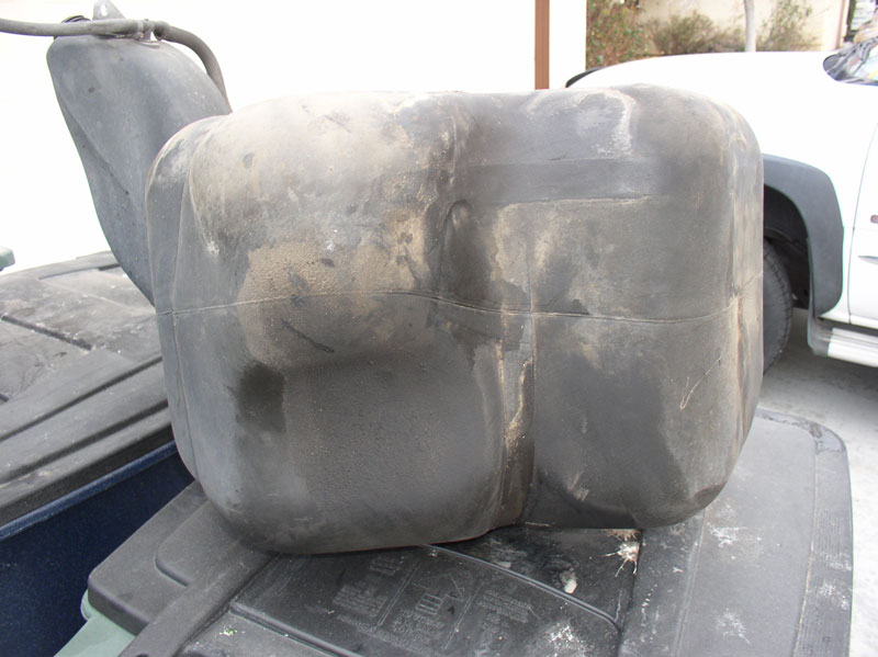
The front side of the tank looked dry too without any signs of staining.
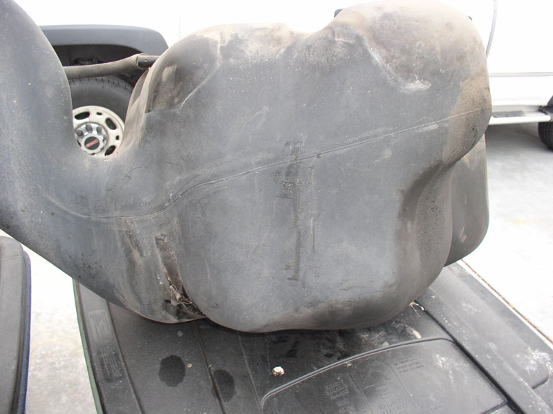
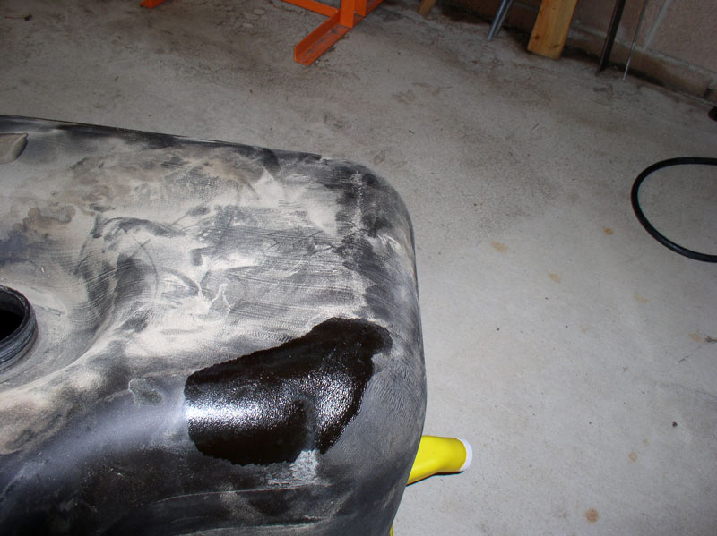
The front corner, however showed signs of fuel staining.
Since it was only leaking when the fuel tank was filled to capacity, I focused my search at the top and SURPRISE! A crack had developed in the top of the tank. This looked like a naturally occurring split and did not resemble something you would expect to find from drilling through the hatch floor. There were no signs of drilling through the hatch floor. This tank failure seems odd to me and I’m curious if it’s common?

To test my theory that this was the source of the leak. I left about a cup of fuel in the tank and turned it upside down to see if any fuel would come through. Sure enough!
Now I was REALLY glad I bought that spare used fuel tank from 928 Intl.!!
RE-INSTALLING THE FUEL TANK
Now’s the time to inspect your hoses and replace as needed. I had replaced the fuel hoses, pump, filters, gaskets about 2 years ago but I did not replace the vent hoses. I looked these over and they seemed to be in great shape so decided to continue using them. I transferred these to the new tank.
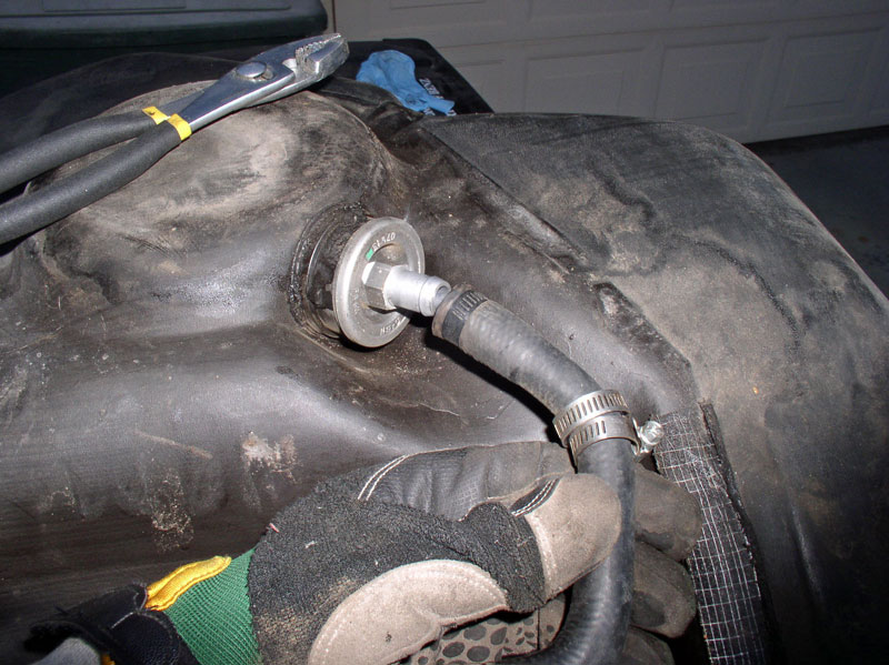
I removed the fuel hose (still fairly new)….
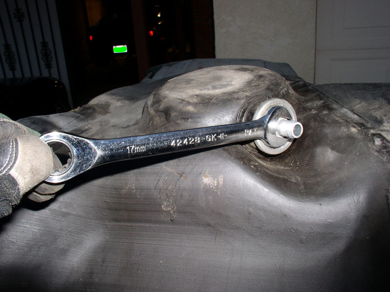
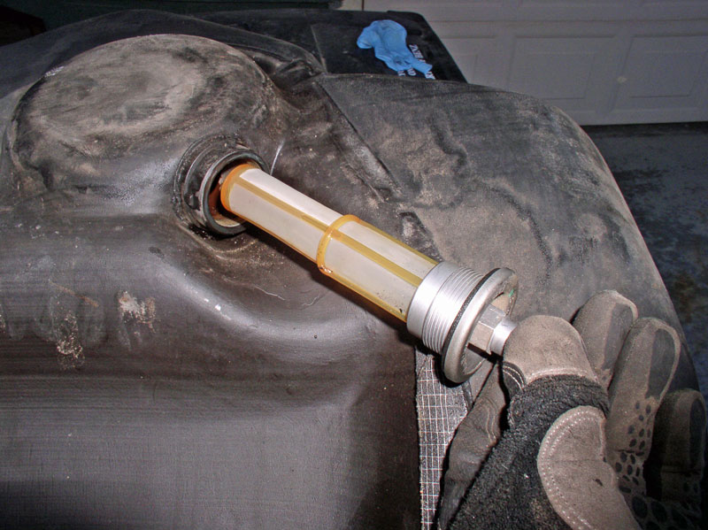
…and the internal fuel filter (using a 17mm wrench).
I planned to transfer these to the new tank.
Continued....
The front corner, however showed signs of fuel staining.
Since it was only leaking when the fuel tank was filled to capacity, I focused my search at the top and SURPRISE! A crack had developed in the top of the tank. This looked like a naturally occurring split and did not resemble something you would expect to find from drilling through the hatch floor. There were no signs of drilling through the hatch floor. This tank failure seems odd to me and I’m curious if it’s common?
To test my theory that this was the source of the leak. I left about a cup of fuel in the tank and turned it upside down to see if any fuel would come through. Sure enough!
Now I was REALLY glad I bought that spare used fuel tank from 928 Intl.!!
RE-INSTALLING THE FUEL TANK
Now’s the time to inspect your hoses and replace as needed. I had replaced the fuel hoses, pump, filters, gaskets about 2 years ago but I did not replace the vent hoses. I looked these over and they seemed to be in great shape so decided to continue using them. I transferred these to the new tank.
I removed the fuel hose (still fairly new)….
…and the internal fuel filter (using a 17mm wrench).
I planned to transfer these to the new tank.
Continued....
Last edited by Dwayne; 01-08-2011 at 01:21 PM.
01-08-2011, 01:38 PM
#7
Rennlist Member
Thread Starter
Join Date: Sep 2007
Location: Ridgecrest, California
Posts: 1,363
Likes: 0
Received 143 Likes
on
28 Posts
After cleaning the gravel and grime from the fuel tank strap, I noticed the foam padding had deteriorated and needed to be replaced. I found a suitable replacement that seems to work well � Rubber Mastic Tape in the 1� wide variety. The tape I used is about 1.65mm thick which seemed to be adequate.
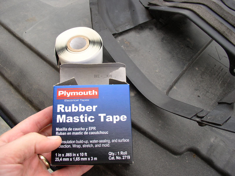
The 1� width was perfect for matching the width of the straps. The tape has adhesive on one side that helps hold it in place while positioning the strap onto the fuel tank.
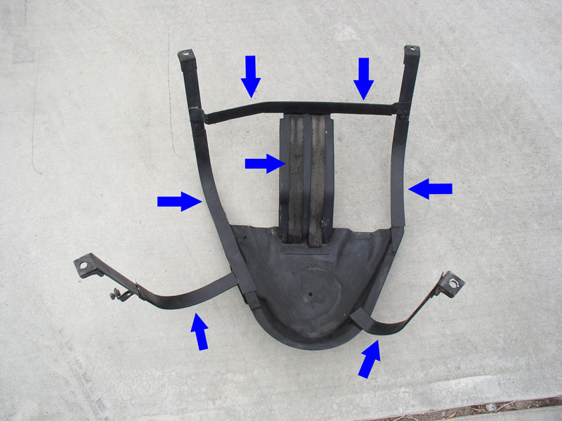
I cut lengths of tape to match the lengths of the existing foam (as determined by the left over adhesive residue on the straps) and applied it to all the areas indicated by the BLUE arrows in the picture below with the exception of the two center foam strips. For some reason, these were still in great shape so I left those alone.
Under the rear hatch floor, there was another area where the foam padding had fallen off. I cleaned the surface area and applied a strip of the Rubber Mastic Tape there as well.
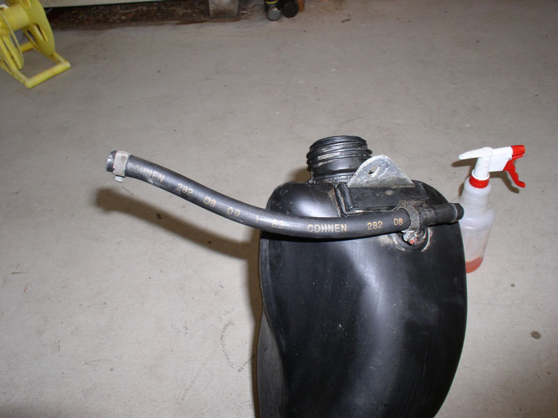
Next, I cleaned and prepared the new fuel tank for installation. I attached the short vent hose and oriented the hose so the �curve� was oriented toward the car body when installed as this is where the canister connection is. Orient the hose clamp at the tank so the screw head will be accessible from the tank filler hole as shown below. I did not tighten the hose clamp at this time as I thought I might need to rotate the hose once the tank was in place.
You will need to attach the larger vent hose at one of the two connection ports. I believe the easier route to go is to connect the vent hose to the connection port at the main tank and leave the hose end at the filler neck to be connected after the tank is installed and the house routed through the body frame. Position the hose as it would be when finally installed as pictured below�..
�.then tighten the hose clamp at the main tank as pictured here.
You have the option of installing the internal fuel tank filter and rubber hose that attaches to it while the tank is out of the car. I believe this is easier as you can simply turn the tank upside down and put the filter and hose in with no trouble. However, in this procedure, I installed the tank next and installed the in-tank filter and hose after the tank was in position which was still very easy � either way works. Next, I positioned the fuel tank under the rear of the car and used a floor jack to help hold the tank in place while I maneuvered the vent hose through the body frame.
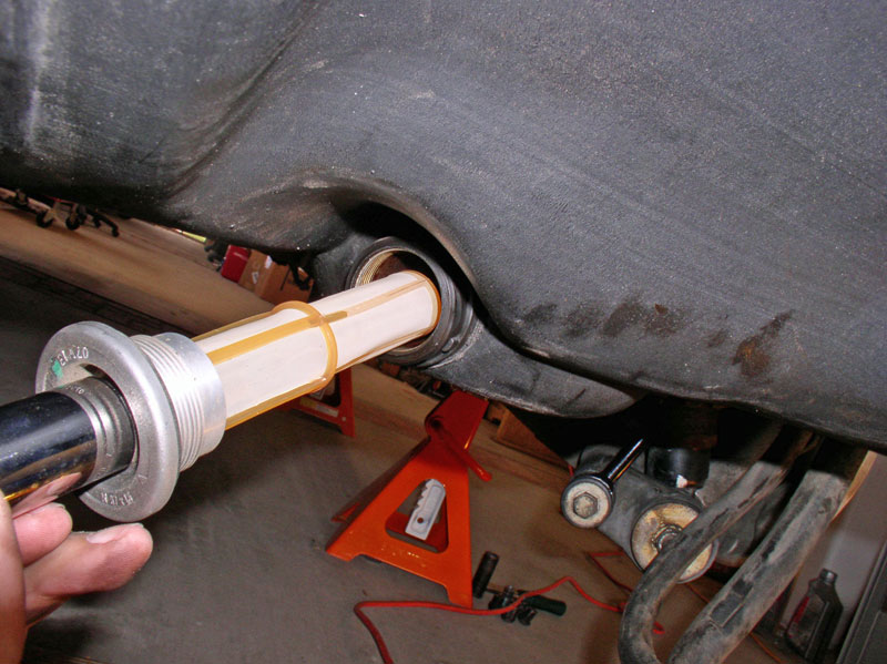
Leave enough room between the fuel tank and body so you can thread the vent hose through the port in the body frame as pictured below.
As you raise the tank up into position, keep threading the hose through the hole and go to the wheel well and pull the hose through. You can try applying some lubricant to the hose to help it slide through the body frame. I decided to try some left over �Personnel Lubricant� I had from Constantine�s Super Bearing Kit since it is water based and shouldn't harm the hose. The vent hose has a textured, fabric outer skin so the lubricant didn�t help as much as I thought but I believe it did make it easier.
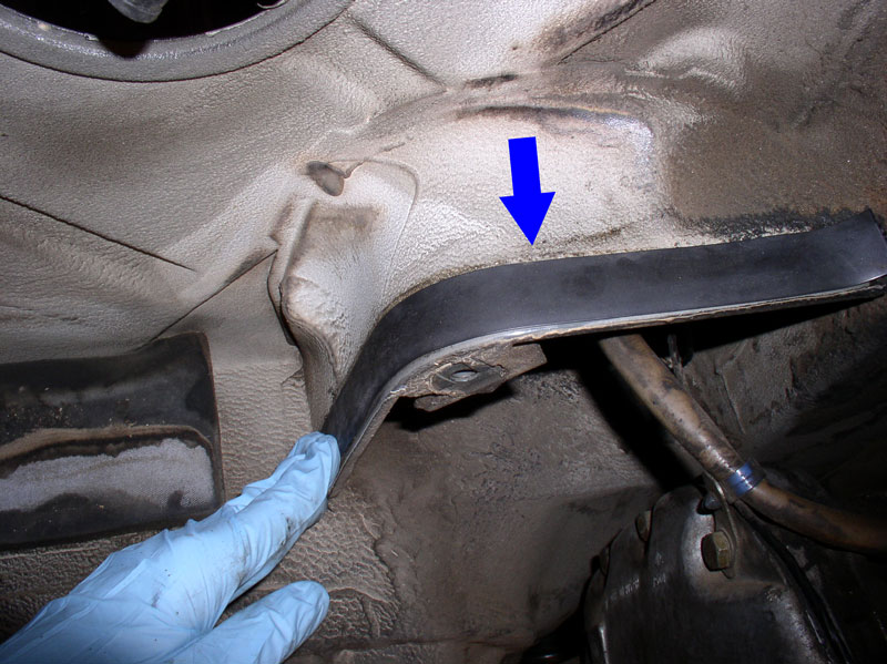
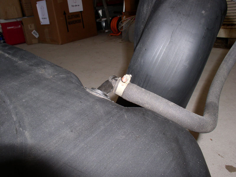
When the hose is in position, the first bend of the hose should be at the body frame and should look like the picture below.
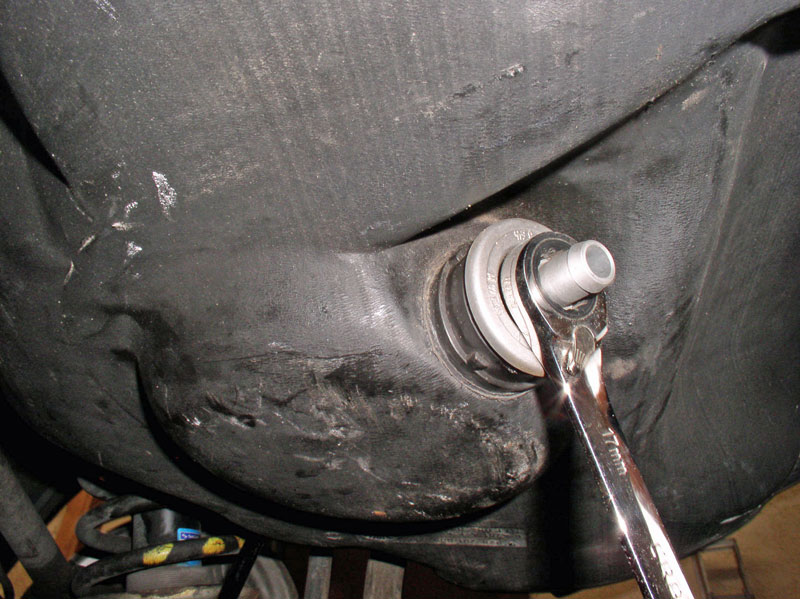
From the gas filler port, the fuel tank is still maneuverable and I found it easy to reach inside and grasp the hose with one hand and reach through the wheel well at the same time to hold the fuel tank filler neck and slide the hose onto the connection port. Ensure the clamp is oriented so the screw head is accessible from the gas filler port as pictured below. Tighten the hose clamp.
Also tighten the smaller vent hose clamp as shown below.
Install the 6mm Allen head bolt and tighten as shown.
Down below, I installed the internal fuel filter. The gasket on the filter threads was still in great shape as I replaced it a couple of years ago.
Continued....
The 1� width was perfect for matching the width of the straps. The tape has adhesive on one side that helps hold it in place while positioning the strap onto the fuel tank.
I cut lengths of tape to match the lengths of the existing foam (as determined by the left over adhesive residue on the straps) and applied it to all the areas indicated by the BLUE arrows in the picture below with the exception of the two center foam strips. For some reason, these were still in great shape so I left those alone.
Under the rear hatch floor, there was another area where the foam padding had fallen off. I cleaned the surface area and applied a strip of the Rubber Mastic Tape there as well.
Next, I cleaned and prepared the new fuel tank for installation. I attached the short vent hose and oriented the hose so the �curve� was oriented toward the car body when installed as this is where the canister connection is. Orient the hose clamp at the tank so the screw head will be accessible from the tank filler hole as shown below. I did not tighten the hose clamp at this time as I thought I might need to rotate the hose once the tank was in place.
You will need to attach the larger vent hose at one of the two connection ports. I believe the easier route to go is to connect the vent hose to the connection port at the main tank and leave the hose end at the filler neck to be connected after the tank is installed and the house routed through the body frame. Position the hose as it would be when finally installed as pictured below�..
�.then tighten the hose clamp at the main tank as pictured here.
You have the option of installing the internal fuel tank filter and rubber hose that attaches to it while the tank is out of the car. I believe this is easier as you can simply turn the tank upside down and put the filter and hose in with no trouble. However, in this procedure, I installed the tank next and installed the in-tank filter and hose after the tank was in position which was still very easy � either way works. Next, I positioned the fuel tank under the rear of the car and used a floor jack to help hold the tank in place while I maneuvered the vent hose through the body frame.
Leave enough room between the fuel tank and body so you can thread the vent hose through the port in the body frame as pictured below.
As you raise the tank up into position, keep threading the hose through the hole and go to the wheel well and pull the hose through. You can try applying some lubricant to the hose to help it slide through the body frame. I decided to try some left over �Personnel Lubricant� I had from Constantine�s Super Bearing Kit since it is water based and shouldn't harm the hose. The vent hose has a textured, fabric outer skin so the lubricant didn�t help as much as I thought but I believe it did make it easier.
When the hose is in position, the first bend of the hose should be at the body frame and should look like the picture below.
From the gas filler port, the fuel tank is still maneuverable and I found it easy to reach inside and grasp the hose with one hand and reach through the wheel well at the same time to hold the fuel tank filler neck and slide the hose onto the connection port. Ensure the clamp is oriented so the screw head is accessible from the gas filler port as pictured below. Tighten the hose clamp.
Also tighten the smaller vent hose clamp as shown below.
Install the 6mm Allen head bolt and tighten as shown.
Down below, I installed the internal fuel filter. The gasket on the filter threads was still in great shape as I replaced it a couple of years ago.
Continued....
Trending Topics
01-08-2011, 01:47 PM
#8
Rennlist Member
Thread Starter
Join Date: Sep 2007
Location: Ridgecrest, California
Posts: 1,363
Likes: 0
Received 143 Likes
on
28 Posts
Tighten the filter using a 17mm wrench or deep socket.
Install the fuel supply hose oriented as pictured below and tighten the clamp.
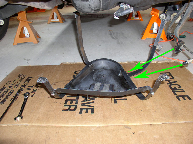
Next, position the tank strap under the fuel tank. You will need to �thread� the fuel pump wiring harness and the fuel supply line into the bottom of the strap plate. There�s an opening indicated by the green arrows below. Thread the harness and fuel line into the plate first while the strap unit is maneuverable.
Then position the tank strap onto the fuel tank as shown below.
While holding the tank strap unit in place with one hand, use the other hand to begin installing the 13mm bolts. I used a long socket extension and started with one of the easier bolts to install � the bolt at the rear of the differential casing. I did not tighten the bolt at this point, just threaded it most of the way to help keep the strap in place while the other bolts are installed.
I installed the bolt at the opposite corner next � the one at the rear corner near the rear bumper shock. This bolt has the added green hard line bracket installed with the bolt. The hard line bracket is placed on top of the strap leg as shown below.
Then came the other rear strap leg. Same routine with the green hard line bracket � placed on top of the strap leg.
The final 13mm bolt is installed next. This time the hard line bracket is placed under the strap leg as shown below.
Before tightening all the strap bolts down, I checked the fuel sending unit port to ensure both wiring harness and fuel return line were accessible. Then I returned to the strap bolts and torqued each one down to 17 ftlbs.
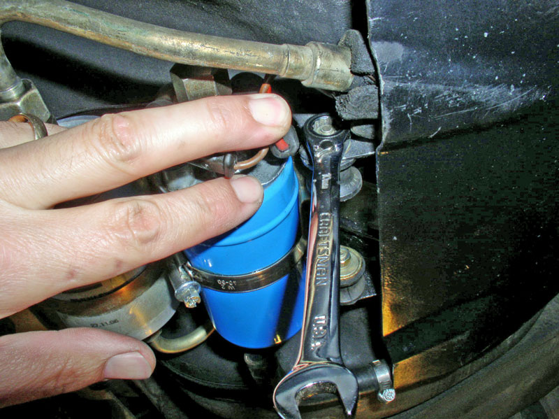
Hold the fuel pump and external fuel filter assembly up next to the wiring harness leads and install the power lead (RED) onto the smaller post and install the 7mm nut but don�t tighten yet. Install the ground lead (BROWN) to the larger post and install the 8mm nut but don�t tighten yet. Next, orient the fuel pump and filter assembly into its installed position on the fuel tank strap bracket and orient the leads so they are not in a bind when the pump and filter is installed. Then tighten the 7mm and 8mm nuts to lock the leads into position.
Continued...
Install the fuel supply hose oriented as pictured below and tighten the clamp.
Next, position the tank strap under the fuel tank. You will need to �thread� the fuel pump wiring harness and the fuel supply line into the bottom of the strap plate. There�s an opening indicated by the green arrows below. Thread the harness and fuel line into the plate first while the strap unit is maneuverable.
Then position the tank strap onto the fuel tank as shown below.
While holding the tank strap unit in place with one hand, use the other hand to begin installing the 13mm bolts. I used a long socket extension and started with one of the easier bolts to install � the bolt at the rear of the differential casing. I did not tighten the bolt at this point, just threaded it most of the way to help keep the strap in place while the other bolts are installed.
I installed the bolt at the opposite corner next � the one at the rear corner near the rear bumper shock. This bolt has the added green hard line bracket installed with the bolt. The hard line bracket is placed on top of the strap leg as shown below.
Then came the other rear strap leg. Same routine with the green hard line bracket � placed on top of the strap leg.
The final 13mm bolt is installed next. This time the hard line bracket is placed under the strap leg as shown below.
Before tightening all the strap bolts down, I checked the fuel sending unit port to ensure both wiring harness and fuel return line were accessible. Then I returned to the strap bolts and torqued each one down to 17 ftlbs.
Hold the fuel pump and external fuel filter assembly up next to the wiring harness leads and install the power lead (RED) onto the smaller post and install the 7mm nut but don�t tighten yet. Install the ground lead (BROWN) to the larger post and install the 8mm nut but don�t tighten yet. Next, orient the fuel pump and filter assembly into its installed position on the fuel tank strap bracket and orient the leads so they are not in a bind when the pump and filter is installed. Then tighten the 7mm and 8mm nuts to lock the leads into position.
Continued...
01-08-2011, 01:57 PM
#9
Rennlist Member
Thread Starter
Join Date: Sep 2007
Location: Ridgecrest, California
Posts: 1,363
Likes: 0
Received 143 Likes
on
28 Posts
Install the protective boots over the fuel pump terminals.
Then slide the fuel pump and filter assembly into the mounting bracket on the fuel tank strap as shown.
Install the flat washer, then the lock washer and the 10mm nut and tighten the four mounting nuts.
One of the nuts is tucked away next to the fuel line and wiring harness but is still accessible with a gear wrench and holding the wiring aside.
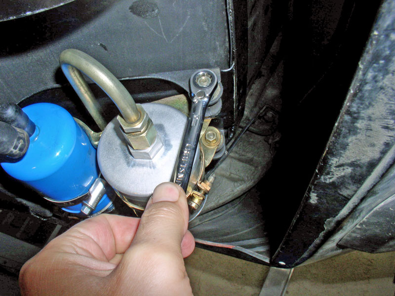
Position the fuel hard line that exits from the fuel filter onto the filter output port. Before installing the nut, I ensured the hard line end was seated properly in the receiving end of the filter then slid the nut down and threaded it.
Tighten the 19mm nut on the hard line as shown. Counter hold the filter side with a second 19mm wrench.
Install the fuel supply hose on the input side of the fuel pump as shown and tighten the hose clamp.
At the wheel well, position the wiring harness and fuel line so that one is on either side of the cover plate mounting stud as indicated by the green arrows below. Then place the plastic cover into position�.
�.ensuring the end of the cover slides into the fuel tank strap bottom plate as shown below.
Install and tighten the 10mm nut.
Install the vent hose on the canister port and tighten the hose clamp.
At the fuel door, position the fuel filler grommet into the filler port with the drain tube pointing down.
You will notice a groove molded into the grommet that is positioned over the lip of the fuel port opening.
When the grommet is installed properly, it is fully seated against the body as shown below.
Install the drain tube extension.
Continued....
Then slide the fuel pump and filter assembly into the mounting bracket on the fuel tank strap as shown.
Install the flat washer, then the lock washer and the 10mm nut and tighten the four mounting nuts.
One of the nuts is tucked away next to the fuel line and wiring harness but is still accessible with a gear wrench and holding the wiring aside.
Position the fuel hard line that exits from the fuel filter onto the filter output port. Before installing the nut, I ensured the hard line end was seated properly in the receiving end of the filter then slid the nut down and threaded it.
Tighten the 19mm nut on the hard line as shown. Counter hold the filter side with a second 19mm wrench.
Install the fuel supply hose on the input side of the fuel pump as shown and tighten the hose clamp.
At the wheel well, position the wiring harness and fuel line so that one is on either side of the cover plate mounting stud as indicated by the green arrows below. Then place the plastic cover into position�.
�.ensuring the end of the cover slides into the fuel tank strap bottom plate as shown below.
Install and tighten the 10mm nut.
Install the vent hose on the canister port and tighten the hose clamp.
At the fuel door, position the fuel filler grommet into the filler port with the drain tube pointing down.
You will notice a groove molded into the grommet that is positioned over the lip of the fuel port opening.
When the grommet is installed properly, it is fully seated against the body as shown below.
Install the drain tube extension.
Continued....
01-08-2011, 02:07 PM
#10
Rennlist Member
Thread Starter
Join Date: Sep 2007
Location: Ridgecrest, California
Posts: 1,363
Likes: 0
Received 143 Likes
on
28 Posts
Insert the gas cap cover flap ring into the groove on the inside of the grommet as shown.
 ]
]
Install the fuel door. Test fit the door to ensure it is aligned properly when it�s closed. The mounting bracket has some adjustment under the Phillips screws to ensure the gaps between the edge of the door and the cut out in the body are all consistent when the door is shut.
Lower the fuel level sending unit into the tank.
Install the plastic nut over the top before attaching the hose or electrical harness.
Ensure the fuel level sending unit gasket is seated at the top of the unit and is not distorted in any way. I found it easier to connect the fuel return hose to the fuel level sending unit when the unit was not yet set in place � more maneuverable. Therefore, I installed the hose first then I positioned the sending unit into the tank opening and pressed it down in to place. It was a snug fit but it snapped into place. Ensure the gasket is flush all around � I did this by touch. Installing the hose before securing the plastic nut does make it slightly more difficult to get the nut started because the plastic nut will rub against the hose at first when tightening but after a half a turn, it all clear.
Tighten down the fuel level sending unit plastic nut. I used a pair of oil filter pliers.
Install the wiring harness plug. It is keyed so it will only go on one way.
Tighten the fuel return hose clamp.
I would recommend leaving the cover off the fuel level sender access hole and leaving the cover off the fuel pump and filter under the fuel tank so you can check for leaks.
Now you are ready to put some fuel into the tank and check for leaks. I had exactly 5 gallons of fresh gas standing by in a can. Since I had drained the tank, I was curious exactly how much gas the empty tank would take � would it be 22 gallons as advertised? I added about a gallon at first then waited a few minutes. I then inspected underneath the tank at the fuel pump and filter � everything was dry. I proceeded to add the remaining gas in the can � 5 gallons total. Still no leaks.
At this point, I decided to start the car and check for leaks. I started the car and let it run a couple of minutes and checked for leaks at the pump/filter and at the fuel return line in the rear hatch area. Still no leaks.
I re-installed the right rear wheel and lowered the car. Started it up and drove to the nearby (1 mile away) gas station and filled up the tank and topped it off. It took exactly 17 gallons. Plus the 5 I put in before made 22 exactly. I checked again for leaks at the fuel pump/filter and the fuel return line. No leaks. Drove the car home and checked again. Still no leaks. It is so nice to be able to fill up the tank and not have gas dripping! Problem solved!!
After these checks, you can re-install the fuel pump cover and the fuel level sending unit covers in the hatch area and button thing up.
CONGRATULATIONS! You�re Done eliminating that pesky fuel leak and helped reduce the risk of toasting your 928!
Please feel free to post comments or recommendations. I welcome feedback that would improve the quality of this post. THANKS for reading!
]Install the fuel door. Test fit the door to ensure it is aligned properly when it�s closed. The mounting bracket has some adjustment under the Phillips screws to ensure the gaps between the edge of the door and the cut out in the body are all consistent when the door is shut.
Lower the fuel level sending unit into the tank.
Install the plastic nut over the top before attaching the hose or electrical harness.
Ensure the fuel level sending unit gasket is seated at the top of the unit and is not distorted in any way. I found it easier to connect the fuel return hose to the fuel level sending unit when the unit was not yet set in place � more maneuverable. Therefore, I installed the hose first then I positioned the sending unit into the tank opening and pressed it down in to place. It was a snug fit but it snapped into place. Ensure the gasket is flush all around � I did this by touch. Installing the hose before securing the plastic nut does make it slightly more difficult to get the nut started because the plastic nut will rub against the hose at first when tightening but after a half a turn, it all clear.
Tighten down the fuel level sending unit plastic nut. I used a pair of oil filter pliers.
Install the wiring harness plug. It is keyed so it will only go on one way.
Tighten the fuel return hose clamp.
I would recommend leaving the cover off the fuel level sender access hole and leaving the cover off the fuel pump and filter under the fuel tank so you can check for leaks.
Now you are ready to put some fuel into the tank and check for leaks. I had exactly 5 gallons of fresh gas standing by in a can. Since I had drained the tank, I was curious exactly how much gas the empty tank would take � would it be 22 gallons as advertised? I added about a gallon at first then waited a few minutes. I then inspected underneath the tank at the fuel pump and filter � everything was dry. I proceeded to add the remaining gas in the can � 5 gallons total. Still no leaks.
At this point, I decided to start the car and check for leaks. I started the car and let it run a couple of minutes and checked for leaks at the pump/filter and at the fuel return line in the rear hatch area. Still no leaks.
I re-installed the right rear wheel and lowered the car. Started it up and drove to the nearby (1 mile away) gas station and filled up the tank and topped it off. It took exactly 17 gallons. Plus the 5 I put in before made 22 exactly. I checked again for leaks at the fuel pump/filter and the fuel return line. No leaks. Drove the car home and checked again. Still no leaks. It is so nice to be able to fill up the tank and not have gas dripping! Problem solved!!
After these checks, you can re-install the fuel pump cover and the fuel level sending unit covers in the hatch area and button thing up.
CONGRATULATIONS! You�re Done eliminating that pesky fuel leak and helped reduce the risk of toasting your 928!
Please feel free to post comments or recommendations. I welcome feedback that would improve the quality of this post. THANKS for reading!
The following users liked this post:
Hey_Allen (07-22-2019)
01-08-2011, 02:33 PM
#11
Rennlist Member
I did this job a year and a half ago. You make me want to do it again just to follow your write-up. Gretch, please put this in the DIY as soon as you can.
Great job as always Dwayne. Thank you.
Great job as always Dwayne. Thank you.
Last edited by robot808; 01-12-2011 at 09:52 PM.
 01-08-2011, 03:38 PM
#13
Burning Brakes
What a timely thread!!!!! My fuel pump has been noisy with this big humming. I was about to buy a replacement fuel pump and replace it myself. With a few more of these excellent threads from Dwayne, I might as well quit my job and rebuild the 928 full time!!!
Many thanks to Dwayne.
Steve
Many thanks to Dwayne.
Steve
03-20-2011, 02:48 PM
#14
Rennlist Member
Hey Dwayne You rock! Thanks for taking all the pictures and the time to describe the whole procedure. I finished mine this weekend. It is nice to be able to fill my tank and not leave a half gallon on the driveway!
03-20-2011, 06:19 PM
#15
Team Owner
Great write up Dwayne your very thorough.
IMHO I did see one thing to add to your parts to buy list, and that is part #13 in the second PET picture, the short metal hose from pump to filter.
NOTE it is very common to have the cap nut overtightened to seal a dripping sealing ring when this happens the hose end will crush slightly this will then deform the end and make the leak worse. the only remedy is to use new sealing rings and replace the short metal hose,
Anytime i do a fuel filter / pump replacement I get one of these hoses to make this a do it once and forget it job,
otherwise you put everything back together only to find that after the tank is filled you now have a leaking pump fitting and 20 gallons of gas behind it


