
Torque Tube, Torque Converter Bearing Replacement Procedure w/pics
 12-20-2010, 11:53 AM
#61
Rennlist Member
Thread Starter
Join Date: Sep 2007
Location: Ridgecrest, California
Posts: 1,363
Likes: 0
Received 143 Likes
on
28 Posts
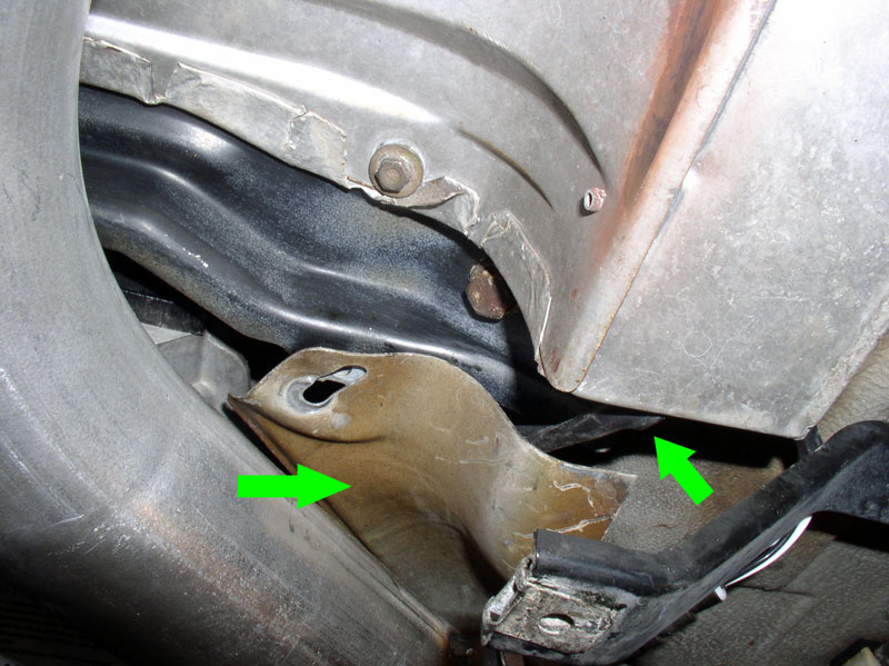
Next, I loosened the lower 19mm bolts that contain the support bracket for the exhaust manifold. I found it was easier to install the X-Pipe to the exhaust manifold if the support bracket could move freely. See picture below.
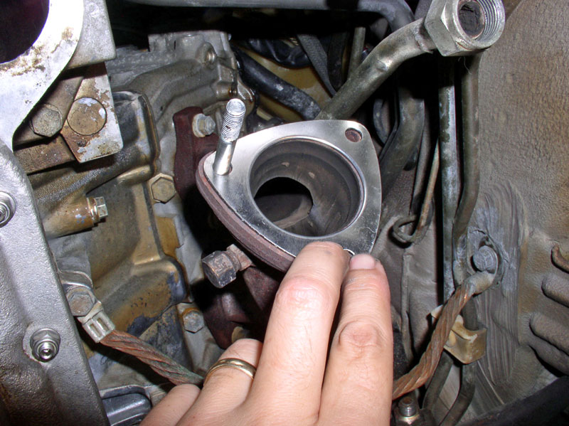
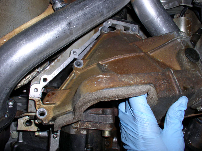
I applied anti-seize to the threads of the bolts for the exhaust manifold-to-X Pipe connection. Position the exhaust manifold gasket as shown in the picture below and insert the bolts to help hold the gasket in place while you attach the X-Pipe.
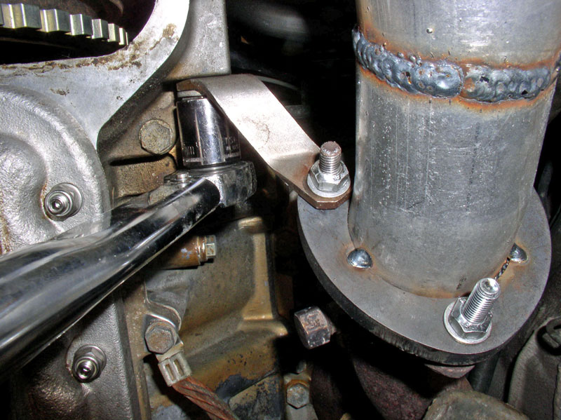
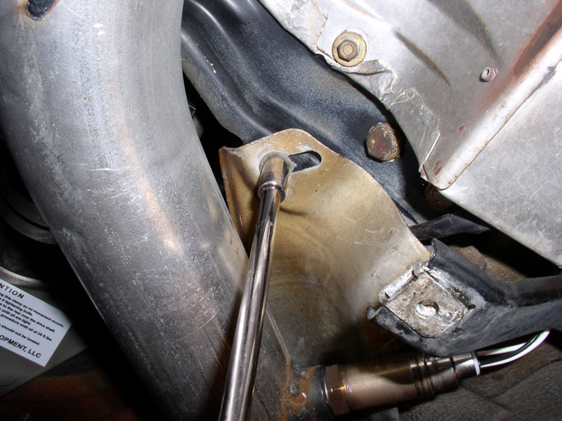
Maneuver the X-Pipe into position so the bolt threads are exposed and install the locknuts. On the right side (passenger side) the manifold support bracket is positioned on the Nut side of the X-Pipe flange as shown in the picture below. The manifold support bracket on the left side (driver�s side) is installed on the bolt head side of the exhaust manifold. When the X-Pipe locknuts are tightened down, torque both of the 19mm lower bell housing bolts to 77 Nm or 56 ftlbs.
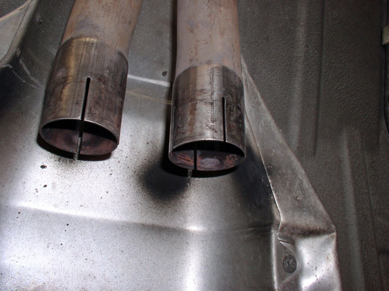
I cleaned the factory exhaust connections with some fine grit sandpaper in preparation for the catalytic converter installation.
First, install the catalytic converter over the rear exhaust pipe and slide it far enough on to the pipe�..
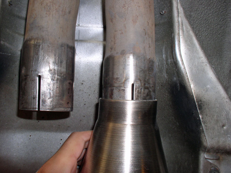
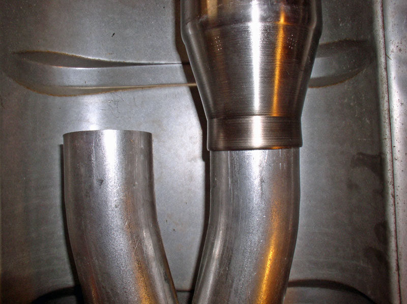
�.to allow enough clearance to slide the front end of the catalytic converter over the X-Pipe as shown below. Center the catalytic converter over the X-Pipe and factory exhaust so that an equal amount of overlap exists on the connections.
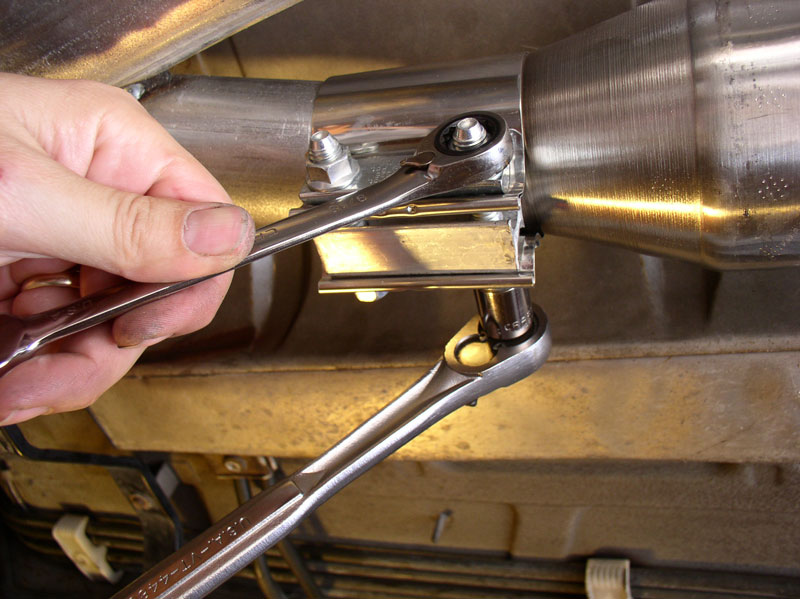
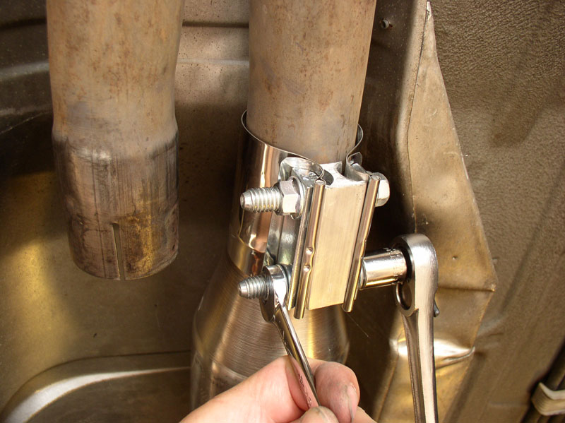
Install the supplied clamps and tighten them down. I started with the forward clamp.
For the rear connection, install the supplied heat resistant woven cloth in accordance with the supplied instructions. I found it a little tricky to hold the cloth in place, keeping it straight, while placing the clamp into position.
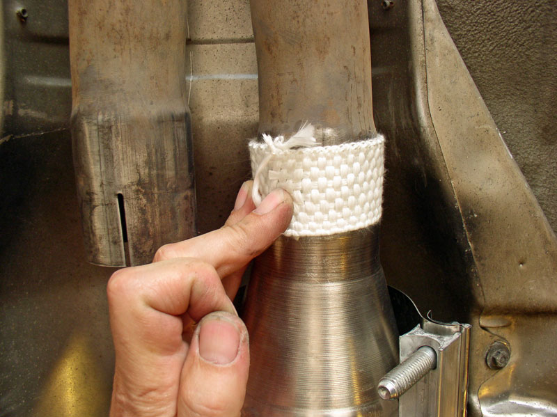
Once the cloth and clamp are in position, tighten the clamp down.
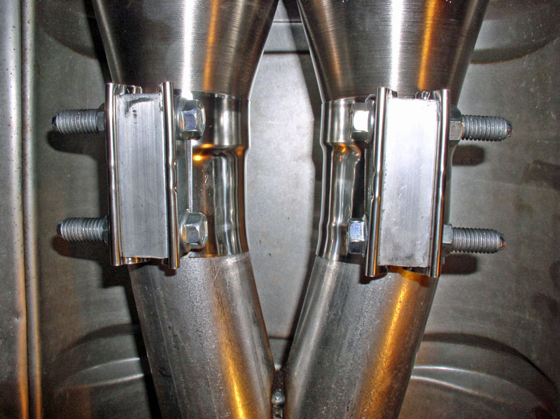
Repeat for the other side. When the clamps are installed properly, the metal band should take the shape of the contour lines of the connection as shown below.
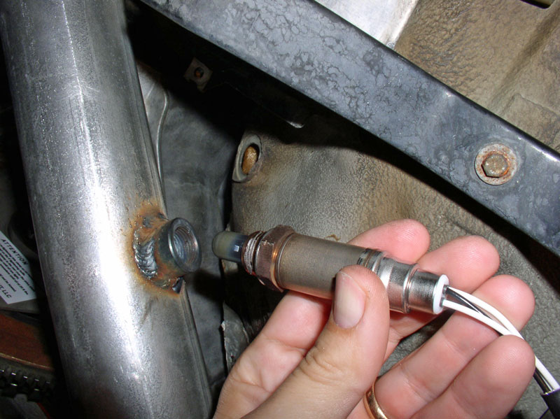
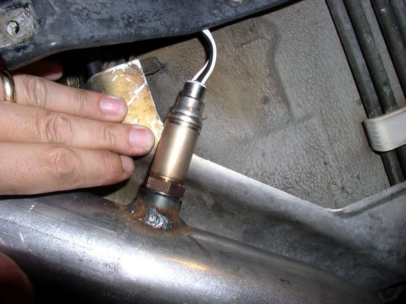
Next, I installed the O2 sensor. I installed a new sensor with factory harness since the previous one had a cracked harness and a spliced connection. The new O2 sensor already came with anti-seize applied to the threads.
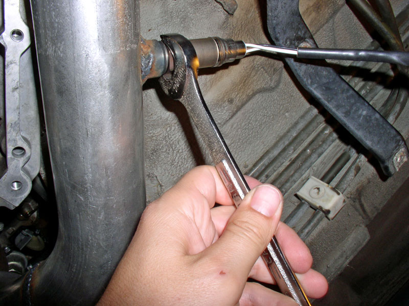
I tightened the O2 sensor down with a 22mm wrench.
I applied some silicone lubricant to the floorboard sealing grommet to aid installation and proper seating of the grommet.
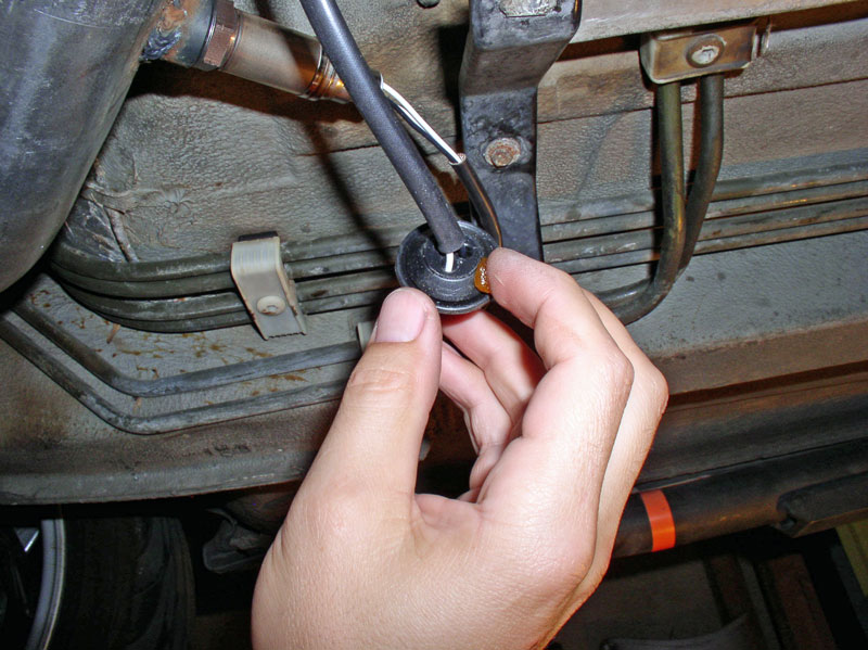
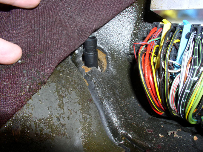
Feed the end of the O2 sensor harness through the access hole in the floorboard as shown.
On the inside of the car at the Central Electric Board, pick up the end of the O2 harness�..
Continued....
I applied anti-seize to the threads of the bolts for the exhaust manifold-to-X Pipe connection. Position the exhaust manifold gasket as shown in the picture below and insert the bolts to help hold the gasket in place while you attach the X-Pipe.
Maneuver the X-Pipe into position so the bolt threads are exposed and install the locknuts. On the right side (passenger side) the manifold support bracket is positioned on the Nut side of the X-Pipe flange as shown in the picture below. The manifold support bracket on the left side (driver�s side) is installed on the bolt head side of the exhaust manifold. When the X-Pipe locknuts are tightened down, torque both of the 19mm lower bell housing bolts to 77 Nm or 56 ftlbs.
I cleaned the factory exhaust connections with some fine grit sandpaper in preparation for the catalytic converter installation.
First, install the catalytic converter over the rear exhaust pipe and slide it far enough on to the pipe�..
�.to allow enough clearance to slide the front end of the catalytic converter over the X-Pipe as shown below. Center the catalytic converter over the X-Pipe and factory exhaust so that an equal amount of overlap exists on the connections.
Install the supplied clamps and tighten them down. I started with the forward clamp.
For the rear connection, install the supplied heat resistant woven cloth in accordance with the supplied instructions. I found it a little tricky to hold the cloth in place, keeping it straight, while placing the clamp into position.
Once the cloth and clamp are in position, tighten the clamp down.
Repeat for the other side. When the clamps are installed properly, the metal band should take the shape of the contour lines of the connection as shown below.
Next, I installed the O2 sensor. I installed a new sensor with factory harness since the previous one had a cracked harness and a spliced connection. The new O2 sensor already came with anti-seize applied to the threads.
I tightened the O2 sensor down with a 22mm wrench.
I applied some silicone lubricant to the floorboard sealing grommet to aid installation and proper seating of the grommet.
Feed the end of the O2 sensor harness through the access hole in the floorboard as shown.
On the inside of the car at the Central Electric Board, pick up the end of the O2 harness�..
Continued....
 12-20-2010, 11:56 AM
#62
Rennlist Member
Thread Starter
Join Date: Sep 2007
Location: Ridgecrest, California
Posts: 1,363
Likes: 0
Received 143 Likes
on
28 Posts
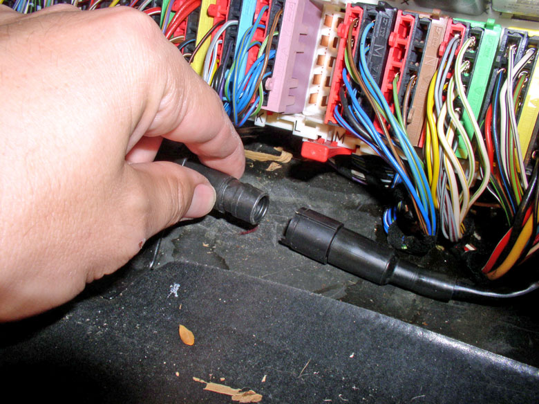
�.and attach it to the connector shown below. The connector is keyed so it will only fit one way.
Press in the sealing grommet so that it is fully seated. Even with the silicone lubricant, it was a bit of a challenge given the confined spaces. I believe it would have been better to install the grommet before the X-Pipe was installed.
Next, I maneuvered the right (passenger side) forward heat shield into place and positioned the O2 sensor harness so that it was behind the heat shield as much as possible for heat protection.
Secure the heat shield into position using the two 8mm screws.
Lastly, I checked the O2 sensor clearance with the heat shield. In my case, the heat shield was lightly touching the O2 sensor. When the engine is running, the exhaust system will vibrate and move while the heat shield won�t. Therefore, I depressed the heat shield to provide some extra clearance between the sensor and shield.
Congratulations, the exhaust system is installed!
12-20-2010, 12:21 PM
#63
Rennlist Member
Thread Starter
Join Date: Sep 2007
Location: Ridgecrest, California
Posts: 1,363
Likes: 0
Received 143 Likes
on
28 Posts
CH17 WRAP UP
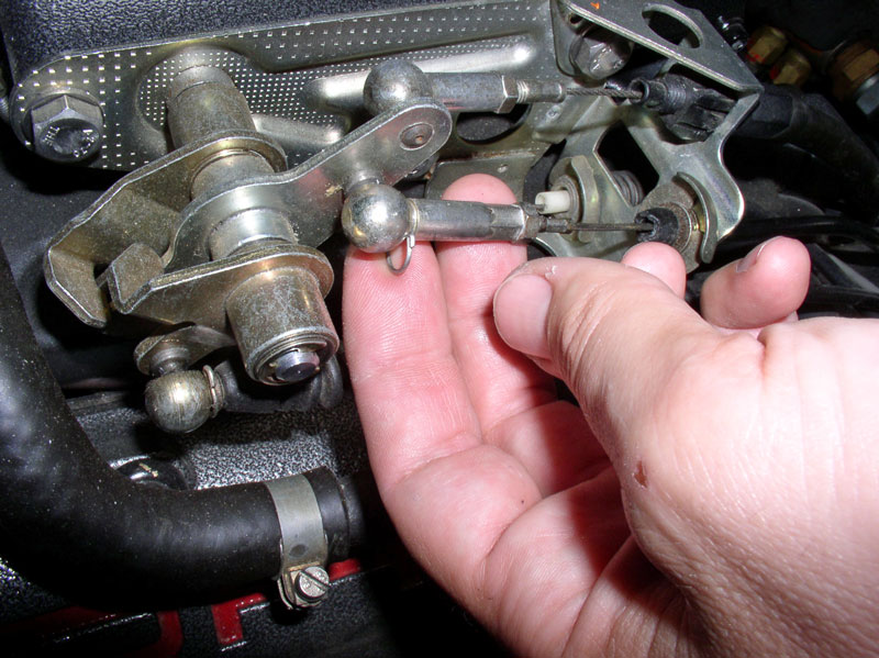
In this final chapter, there are a few miscellaneous items to complete before the job is finished. First, thread the Bowden cable through the throttle linkage bracket as shown below.
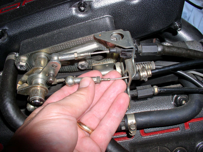
I applied a small amount of white grease to the ball connector on the ball connector stud.
Remove the lock pin from the ball connector. Be careful not to drop it – I found it easy to get away from me.
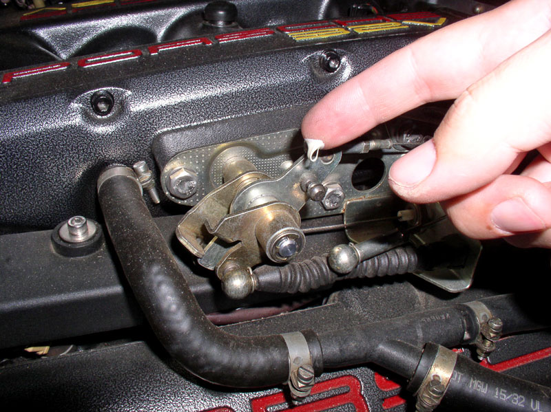
Install the locking clip on the cable harness at the bracket as shown in the picture below.
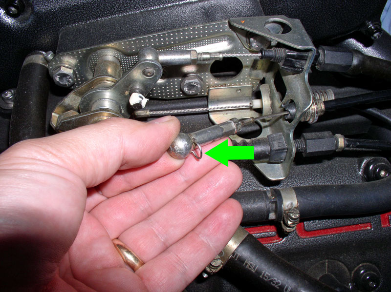
Press the ball connector on the ball stud and re-install the locking pin as shown. Rotate the locking pin so it locks securely in place around the base of the ball connector.
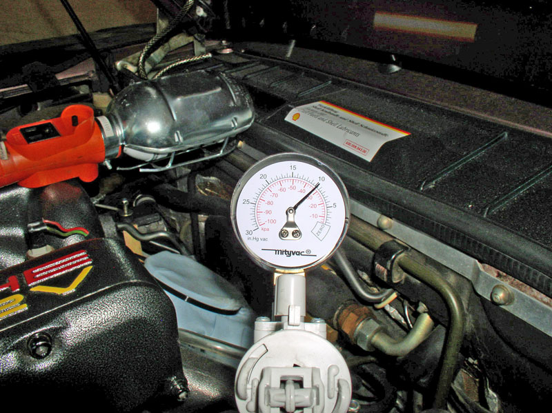
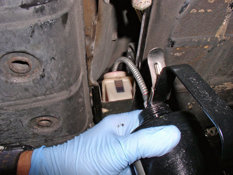
Before reconnecting the vacuum line to the transmission, I decided it would be a good idea to do a final check/test to make sure the vacuum line did not disconnect somewhere during the installation of the transmission and TT. I pulled 10 InHg of vacuum and it held steady for several minutes. Everything OK!
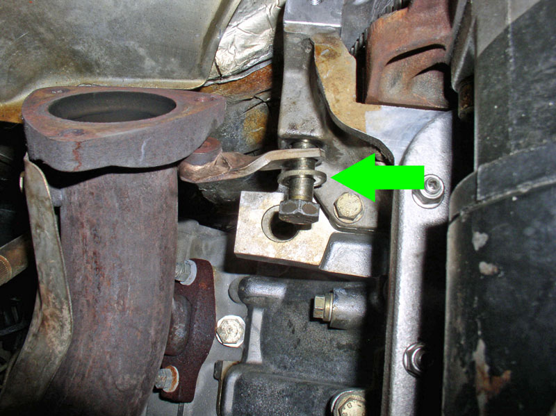
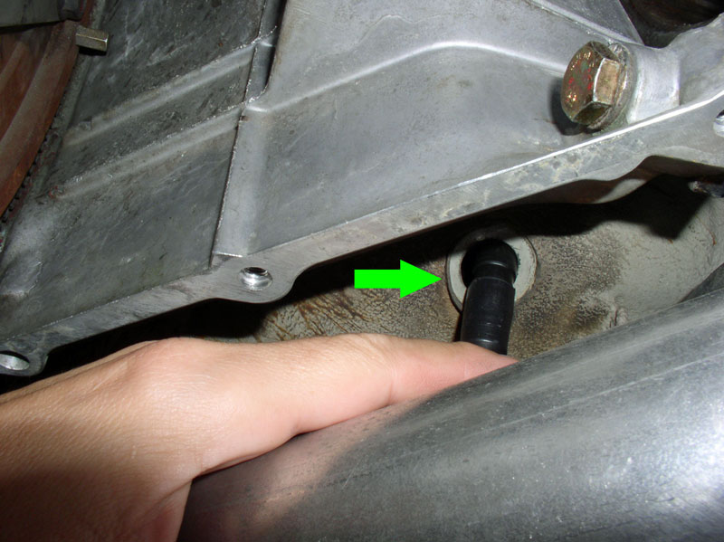
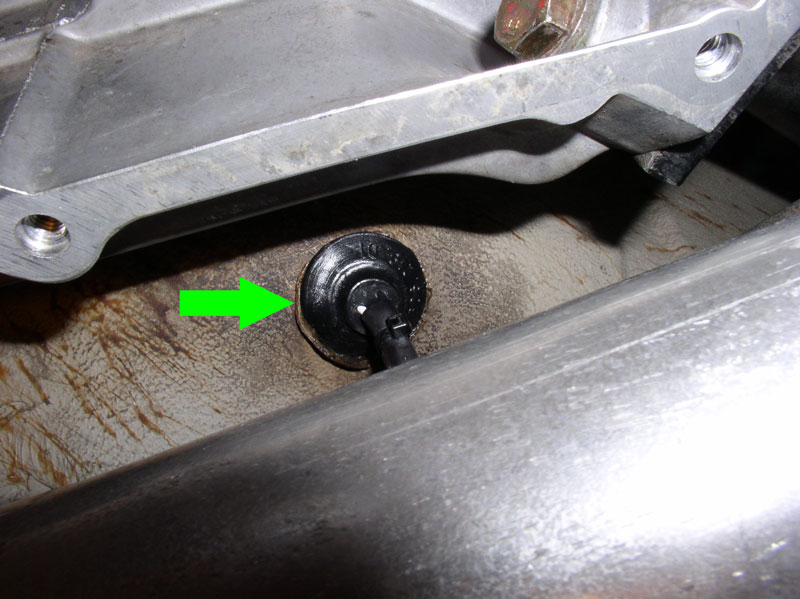
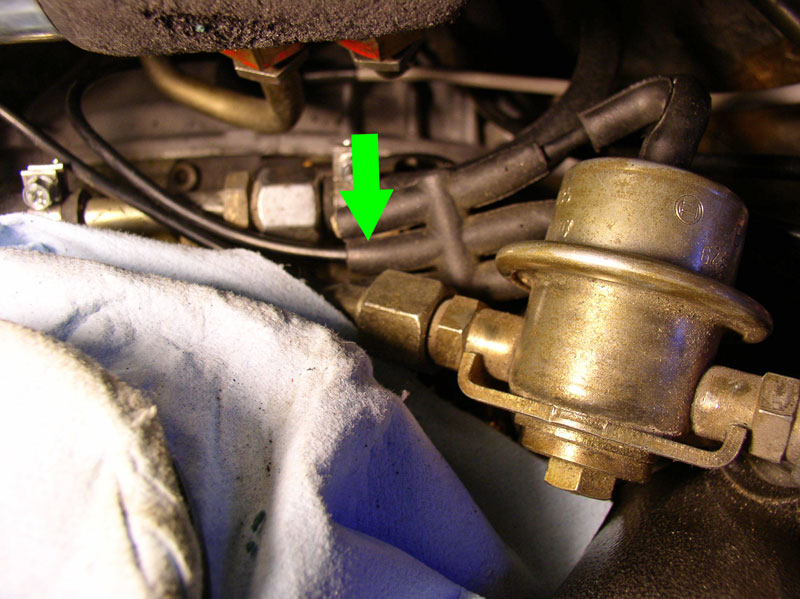
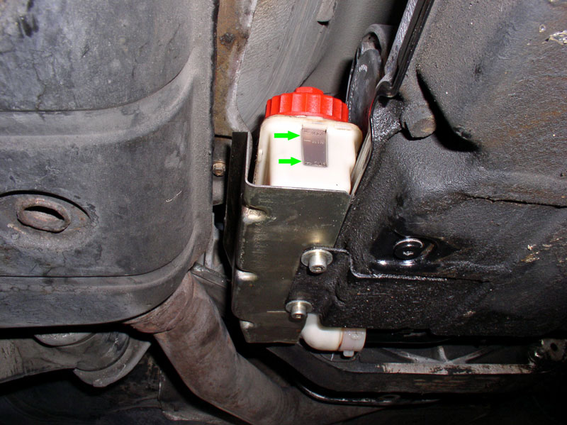
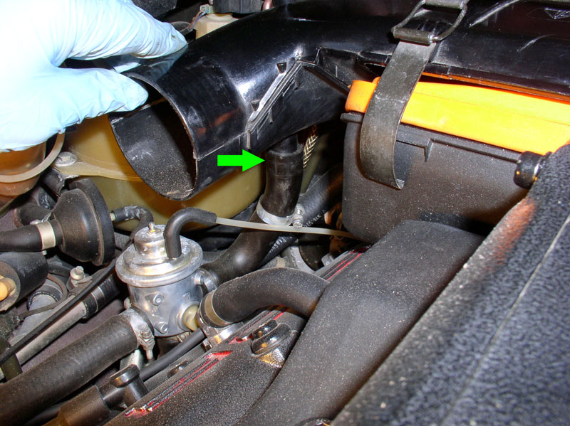
I connected the transmission vacuum line to the rubber vacuum manifold just under the fuel pressure regulator as depicted by the green arrow in the picture below.
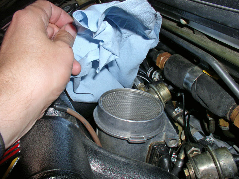
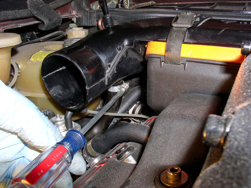
Remove the cover over the MAF. I could have installed the air box and air filter at this time. However, I waited on that since I wanted to add transmission fluid and run the car and check for leaks at the heater control valve before installing the air box.
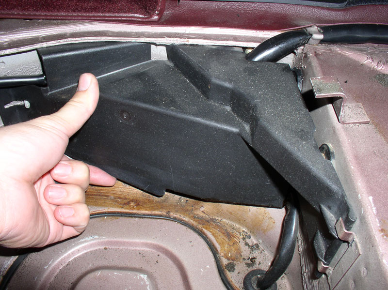
In the spare tire compartment, re-install the harness cover as shown below.
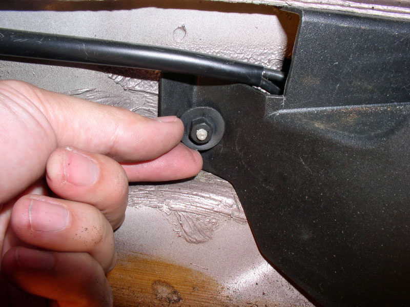
Secure the cover with the 10mm bolt.
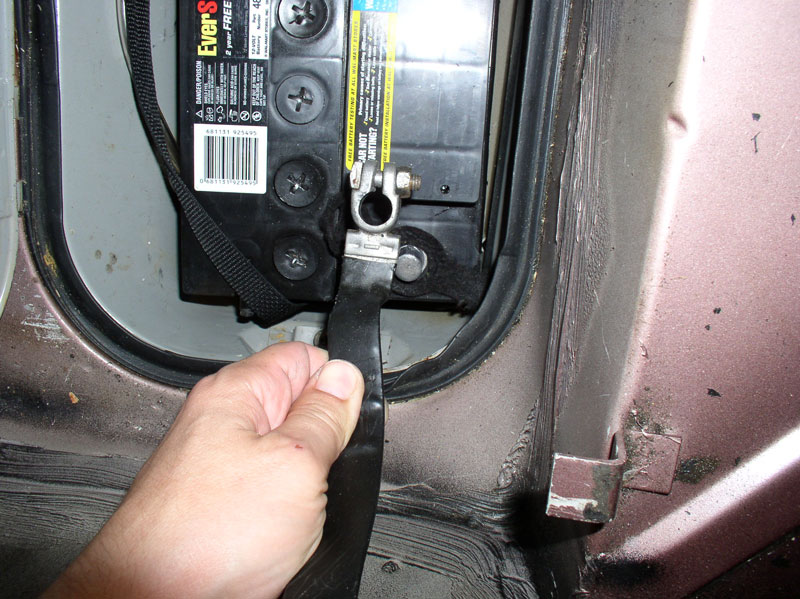
Reconnect the negative battery cable and tighten the 13mm nut on the clamp.
At this point, I began re-filling the transmission with fluid. Use a recommended fluid for the 928. I saved the old fluid and measured the collected amount in gallon and quart containers to determine exactly how much I would add back. In this case, it was 7 quarts. I used a small oil can (used only for transmission fluid) to add fluid to the reservoir. I found that the reservoir/pan will take about 2 quarts maximum of fluid before I had to start the car and pump some fluid into the torque converter. After I filled the reservoir, I started the car and let it run only for about 3-4 seconds. That’s about how long it took for the transmission to pull in the fluid in the reservoir. I then filled the reservoir back up and started the car again to pull in the fluid. I repeated this cycle until I had added back in the same amount of fluid I removed from the transmission/TC.
Even when all the fluid had been added back in, you may find the reservoir looking low on fluid since the car is still cold during the replenishing process. When cold, the transmission fluid level should be at the LOWER mark on the sight window of the reservoir as indicated by the lower green arrow. When the transmission fluid is at operating temperature, about 176 degrees (according to the WSM), the fluid should be between the upper two marks on the sight window as indicated by the upper green arrow. After the car has been driven and fluid temperature is at operating temperature, you can confirm the proper level.
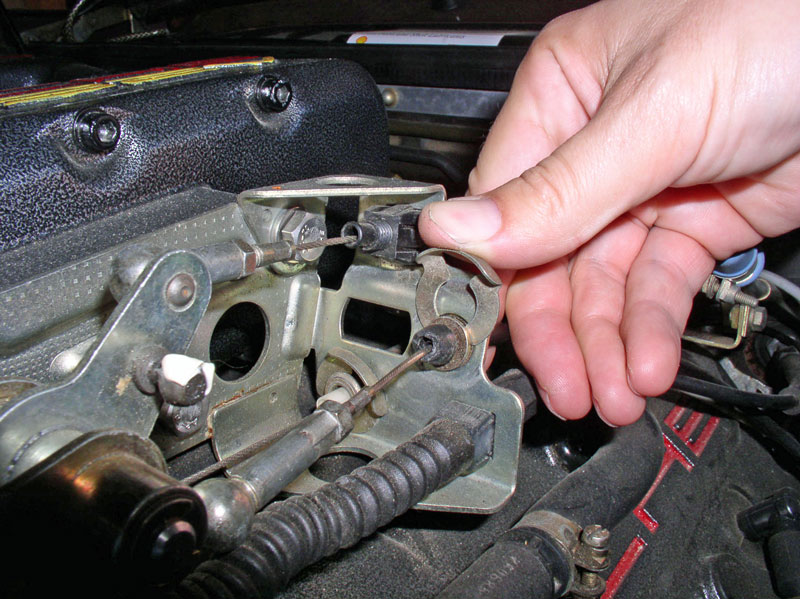
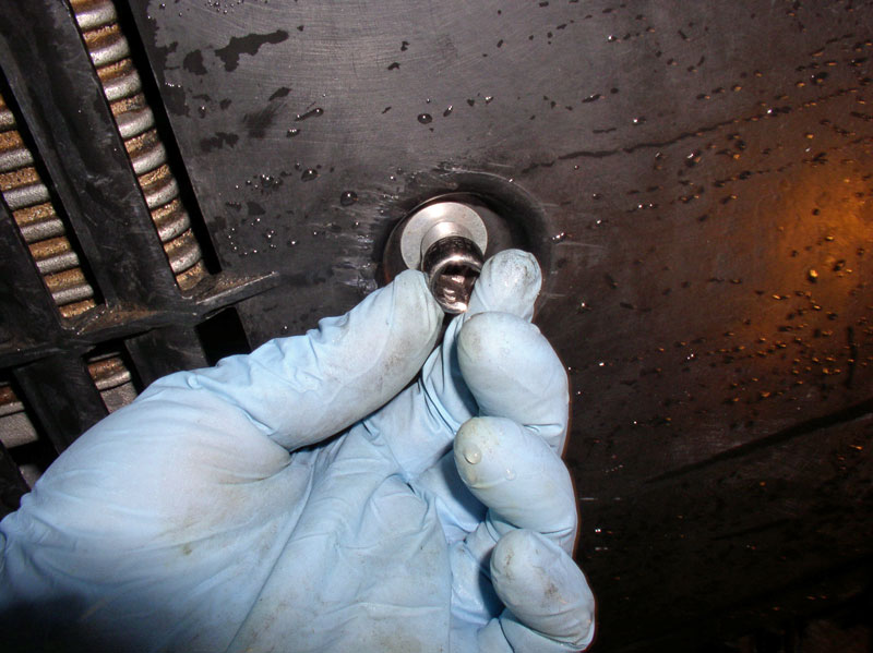
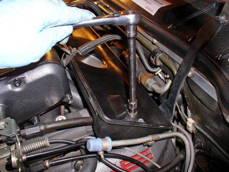
Since the car was run for a little while when adding transmission fluid, I rechecked the flex plate and Super Clamp position before installing the flywheel cover. Everything checked out. Now you can position the cover….
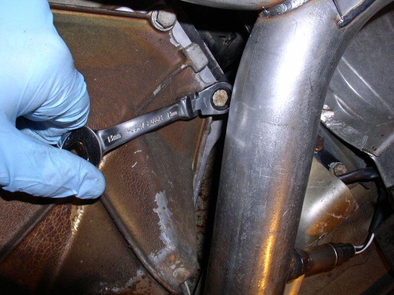
….and install the six 13mm bolts that secure the cover to the upper Bell Housing. I found it easier to install the rear two 13mm bolts using a flex head 13mm ratcheting wrench as shown. If you are still using the factory exhaust, these rearward bolts will not be accessible but I have found it is not critical to install these rear bolts to secure the cover. In fact, it is easier to leave them out so that the cover can be removed at future times without having to remove the exhaust pipe.
Continued...
In this final chapter, there are a few miscellaneous items to complete before the job is finished. First, thread the Bowden cable through the throttle linkage bracket as shown below.
I applied a small amount of white grease to the ball connector on the ball connector stud.
Remove the lock pin from the ball connector. Be careful not to drop it – I found it easy to get away from me.
Install the locking clip on the cable harness at the bracket as shown in the picture below.
Press the ball connector on the ball stud and re-install the locking pin as shown. Rotate the locking pin so it locks securely in place around the base of the ball connector.
Before reconnecting the vacuum line to the transmission, I decided it would be a good idea to do a final check/test to make sure the vacuum line did not disconnect somewhere during the installation of the transmission and TT. I pulled 10 InHg of vacuum and it held steady for several minutes. Everything OK!
I connected the transmission vacuum line to the rubber vacuum manifold just under the fuel pressure regulator as depicted by the green arrow in the picture below.
Remove the cover over the MAF. I could have installed the air box and air filter at this time. However, I waited on that since I wanted to add transmission fluid and run the car and check for leaks at the heater control valve before installing the air box.
In the spare tire compartment, re-install the harness cover as shown below.
Secure the cover with the 10mm bolt.
Reconnect the negative battery cable and tighten the 13mm nut on the clamp.
At this point, I began re-filling the transmission with fluid. Use a recommended fluid for the 928. I saved the old fluid and measured the collected amount in gallon and quart containers to determine exactly how much I would add back. In this case, it was 7 quarts. I used a small oil can (used only for transmission fluid) to add fluid to the reservoir. I found that the reservoir/pan will take about 2 quarts maximum of fluid before I had to start the car and pump some fluid into the torque converter. After I filled the reservoir, I started the car and let it run only for about 3-4 seconds. That’s about how long it took for the transmission to pull in the fluid in the reservoir. I then filled the reservoir back up and started the car again to pull in the fluid. I repeated this cycle until I had added back in the same amount of fluid I removed from the transmission/TC.
Even when all the fluid had been added back in, you may find the reservoir looking low on fluid since the car is still cold during the replenishing process. When cold, the transmission fluid level should be at the LOWER mark on the sight window of the reservoir as indicated by the lower green arrow. When the transmission fluid is at operating temperature, about 176 degrees (according to the WSM), the fluid should be between the upper two marks on the sight window as indicated by the upper green arrow. After the car has been driven and fluid temperature is at operating temperature, you can confirm the proper level.
Since the car was run for a little while when adding transmission fluid, I rechecked the flex plate and Super Clamp position before installing the flywheel cover. Everything checked out. Now you can position the cover….
….and install the six 13mm bolts that secure the cover to the upper Bell Housing. I found it easier to install the rear two 13mm bolts using a flex head 13mm ratcheting wrench as shown. If you are still using the factory exhaust, these rearward bolts will not be accessible but I have found it is not critical to install these rear bolts to secure the cover. In fact, it is easier to leave them out so that the cover can be removed at future times without having to remove the exhaust pipe.
Continued...
Last edited by Dwayne; 12-20-2010 at 12:48 PM.
12-20-2010, 12:33 PM
#64
Rennlist Member
Thread Starter
Join Date: Sep 2007
Location: Ridgecrest, California
Posts: 1,363
Likes: 0
Received 143 Likes
on
28 Posts
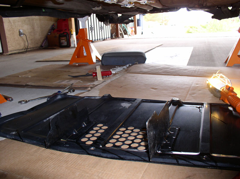
Next, I checked for leaks around the heater control valve and the transmission fluid cooler line connections to ensure all was dry and no leaks present. Everything checked out so I installed the forward belly pan.
Followed by the rear belly pan.
I installed the lower half of the air box next.
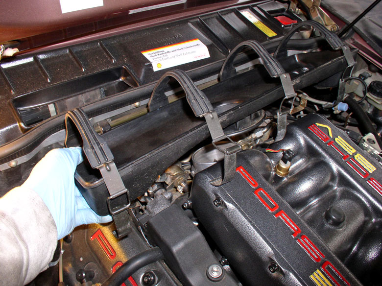
Tighten the four 10mm lock nuts that secure the lower half of the air box.
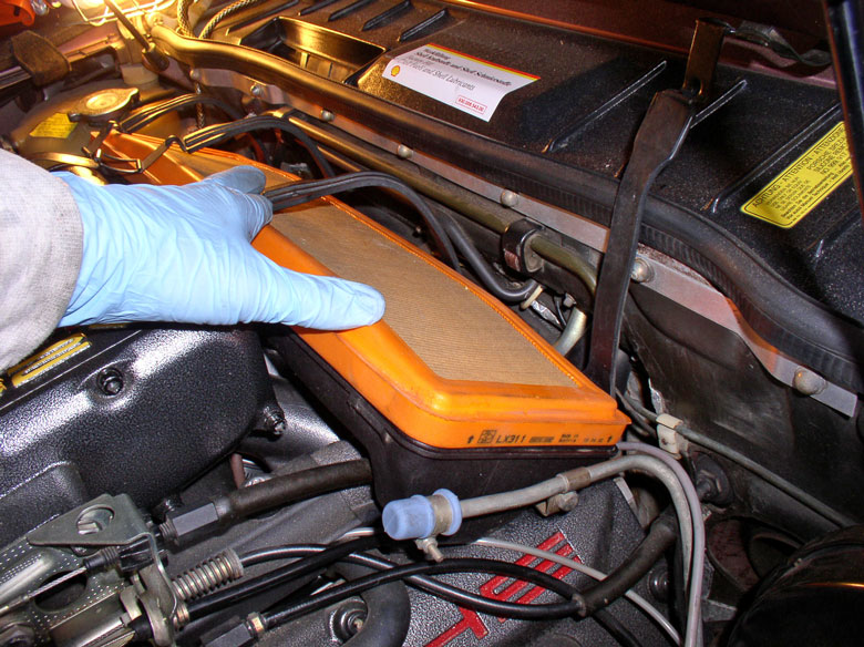
Install the air filter with arrows pointing up as shown below.
Position the upper half of the air box so the air injection control valve hose fits securely on the port on the underside of the right (passenger side) of the tube as shown below.
Position the clamp and tighten.
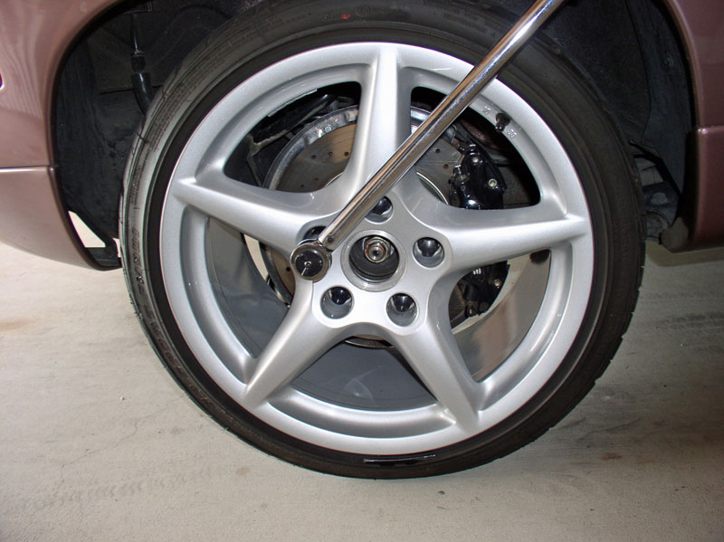
Install the rear wheels and lugnuts.
Lower the car and torque the 19mm lug nuts to 95 ftlbs.
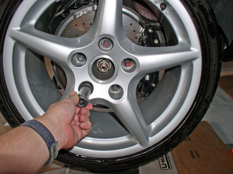
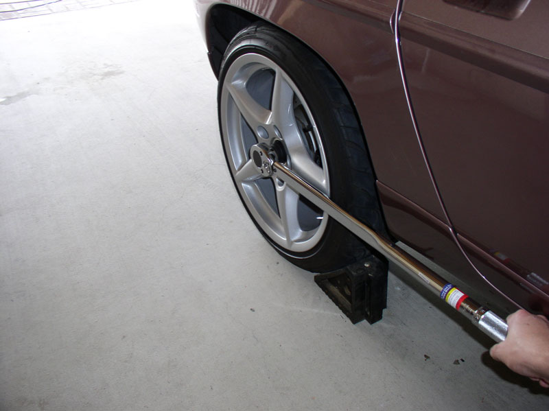
If you removed the axle half shafts, you will need to torque the 32mm axle nut to 460 Nm or 339 ftlbs. I placed the car in Park, set the emergency brake and chocked the wheels to prevent the wheel from turning while torquing the nut. Repeat for the other wheel and install the wheel center caps.
CONGRATULATIONS, YOU ARE DONE!! At this point you can test drive the car and ensure proper operation of the transmission, brakes, emergency brake and (if you were replacing worn out bearings that were making noise) confirm you have eliminated the bearing noise. I would recommend verifying proper transmission fluid level once the car has been driven and the fluid is at operating temperature.
I would like to thank Constantine for making such excellent upgrades for the 928 driveline with his Super Bearings and Super Clamp and the well-written instructions that came with both. I'd also like to thank Constantine for the opportunity to demonstrate the servicing of his Super Bearings. THANK YOU!
Thanks also to Roger Tyson for the excellent service providing the OEM TT bearings and Torque Converter Bearings and X-Pipe!
As I mentioned at the beginning of this post, there are many ways to perform this work with many variations to make it easier. This write up depicted only one of many variations. I welcome other comments, thoughts and ideas that would improve the overall quality of this post. THANKS!
Followed by the rear belly pan.
I installed the lower half of the air box next.
Tighten the four 10mm lock nuts that secure the lower half of the air box.
Install the air filter with arrows pointing up as shown below.
Position the upper half of the air box so the air injection control valve hose fits securely on the port on the underside of the right (passenger side) of the tube as shown below.
Position the clamp and tighten.
Install the rear wheels and lugnuts.
Lower the car and torque the 19mm lug nuts to 95 ftlbs.
If you removed the axle half shafts, you will need to torque the 32mm axle nut to 460 Nm or 339 ftlbs. I placed the car in Park, set the emergency brake and chocked the wheels to prevent the wheel from turning while torquing the nut. Repeat for the other wheel and install the wheel center caps.
CONGRATULATIONS, YOU ARE DONE!! At this point you can test drive the car and ensure proper operation of the transmission, brakes, emergency brake and (if you were replacing worn out bearings that were making noise) confirm you have eliminated the bearing noise. I would recommend verifying proper transmission fluid level once the car has been driven and the fluid is at operating temperature.
I would like to thank Constantine for making such excellent upgrades for the 928 driveline with his Super Bearings and Super Clamp and the well-written instructions that came with both. I'd also like to thank Constantine for the opportunity to demonstrate the servicing of his Super Bearings. THANK YOU!
Thanks also to Roger Tyson for the excellent service providing the OEM TT bearings and Torque Converter Bearings and X-Pipe!
As I mentioned at the beginning of this post, there are many ways to perform this work with many variations to make it easier. This write up depicted only one of many variations. I welcome other comments, thoughts and ideas that would improve the overall quality of this post. THANKS!
12-20-2010, 01:12 PM
#65
Pro
Thanks for the detailed write-up! Great timing as I will be re-installing my trans and TT soon with Constantine's SuperBearings. Gave me some good reminders and tips to follow!
12-20-2010, 02:01 PM
#66
Rennlist Member
Thread Starter
Join Date: Sep 2007
Location: Ridgecrest, California
Posts: 1,363
Likes: 0
Received 143 Likes
on
28 Posts
Dwayne - my hats off to you - this is very impressive stuff! If you're not a professional mechanic, I would like to know what you do for a living. Just fantastic, very helpful even to me, and I am a professional mechanic. By the way, the car in the picture appears to have the same burgundy interior as my '83, which I'm in the middle of returning to correct. That leather is no longer available, and has turned into quite the project for me. I'm now 8 months into it with no real end in sight, so take good care of yours. I guess if you own 6 of these cars, you probably know just about everything there is to know already.
Ben
Ben
Thanks for the comment! I earn a living being a manager. I'm a computer scientist but don't do any of that work any more. I do like to understand how mechanical things work and love working on these cars. The burgundy interior you reference is on my wife's daily driver (Virginia). We live in the high desert but keep the car in the garage anytime it's not being driven. I hope your interior project is going well and you can share some pics with the community. Thanks for reading!
Dwayne,
That's quite a bit of weight to safely balance on two floor jacks. I made a cradle from plywood and 2x2's, similar to what's shown in the WSM.....

Also, the new torque converter bearings will fall right in, no pounding necessary, if you heat the torque converter housing in an oven, also as described in the WSM.
That's quite a bit of weight to safely balance on two floor jacks. I made a cradle from plywood and 2x2's, similar to what's shown in the WSM.....
Also, the new torque converter bearings will fall right in, no pounding necessary, if you heat the torque converter housing in an oven, also as described in the WSM.
I like the cradle you fabricated and thought about making one too (or something that would support the transmission by the transmission mounts). I like the idea of keeping the weight off the transmission pan but if the weight is distributed evenly on the pan, it's less of a concern. If I knew how to weld, I'd like to make some device out of steel. I really like the transmission dolly in your picture, too. The disadvantage I found with the floor jacks is they are not very maneuverable. Your dolly has 4 wheels that swivel and it provides a larger surface area to support the transmission. I've seen these at HF and often considered buying one. Definitely a recommended item.
I've also considered heating the TC housing as you propose and would like to give that a try on my next TC bearing replacement job. THANKS for the tip and for reading!
Nice writeup Dwayne and lots of great pictures,
I would add a few things..
First
I would suggest to leave the reservoir on the pan,
More important, dont remove the hose from the tank but rather from the side of the trans.
\ NOTE this is a metal tube instead of the plastic spout on the tank ( the plastic spout snaps off easily requiring a new tank)
From your pictures if you inspect the front cooler lines above the Cats you may see they are damp,
this indicates a need for new flex hoses to be installed,
your rear lines may be dry but i would also suggest to replace the rear flex lines as well.
NOTE car fires due to ATF fires start over the CATS due to leaking front flex lines, the hard lines can be reused.
Take special note of how far up the cooler lines run along the TT
If they are not positioned up far enough then they will contact the heat shield and possibly catch fire from the CAT heat.
And also make vibration , this situation will be worse with worn motor mounts.
It is a good idea to have new fire resistant sheathing installed on the new flex lines above the CATS.
The old heat sheath will probably be soaked in ATF ,
this can damage the new hose, if the old sheath is used.
Please carry on!
Great advice on the reservoir and the transmission cooler lines. It would be better to disconnect the small rubber hose at the top of the reservoir from the transmission instead of the plastic reservoir for the reason you cite. I'll add the comment to the write up. I tried removing/installing the rear suspension with the fluid reservoir still connected to the transmission when I was working on the '84 but almost cracked it due to the clearance and being new at the procedure. So I tried it without the reservior attached and it seemed easier but with the experience I have now, I would be comfortable with it left on too.
Excellent advice on replacing the hoses too. I plan to revisit these hoses on Virginia in the near future.
THANKS for the great comments! I hope all is going well with your green 5-speed with no sunroof - I'm fixated with non-sunroof 928s!
Dwayne - for situations like that, I've found a crowsfoot extension on the torque wrench affords much better access, as you don't need the space to get a socket in there. Its like an open-ended spanner which fits onto the drive (3/8 in the case of my set) and can sneak into areas without much clearance.
Just work out the correct torque value taking into account the additional length added to the end of the wrench by the crowsfoot.
Just work out the correct torque value taking into account the additional length added to the end of the wrench by the crowsfoot.
The crowsfoot extension sounds like an excellent idea! I've never seen a crowsfoot with extension but it sounds like just the ticket. I'll do a little research to see if I can find one. THANKS for the tip!!
What are you a masochist. My time is valuable - Cut the bell housing it will not hurt your car. You may have bad dreams but you will have more time to sleep.
You should pull the torque converter and front pump. This can be down with the transmission in the car. This is recommended by Mercedes. Replace the torque bearings - about $4 each, the front seal and the oil pump O ring. If either flex plate has rivets they should be replaced by bolts. A port a power is instrumental in removal of the torque bearings.
Here are some pictures
http://www.kondratyev.com/porsche/te...orque_tube.htm
The job is sure a lot easier on the tilter.
Thanks for the comment and alternate method of removing the bearings. The Porta a Power sounds like a very handy tool to have around. Great advice also on replacing the front TC seal and oil pump O-Ring. I would like to try some of the alternate methods of removing the TT and performing the seal and O-Ring repairs with the transmission in the car just to get the experience. I'm still a newb at this and didn't want to bite off more than I could chew. I'm looking forward to the opportunity to do the seal and O-Ring with the transmission in the car in the near future. THANKS for reading!
12-20-2010, 02:11 PM
#67
Rennlist Member
Another excellent write-up. Nice work Dwayne!
One question -- is Constantine no longer recommending using lube to install the super bearing carriers into the TT?
One question -- is Constantine no longer recommending using lube to install the super bearing carriers into the TT?
12-20-2010, 02:17 PM
#68
Rennlist Member
Thread Starter
Join Date: Sep 2007
Location: Ridgecrest, California
Posts: 1,363
Likes: 0
Received 143 Likes
on
28 Posts
from the next set of pictures (removing the rear cross member)
You will also find factory fitted shims between the chassis cross memeber and or the trans to cross member,
make sure to install these in the same position when refitting.
I suggest to use white paint to mark the eccentrics, wire brush the area first.
For exact fitting of the rear cross member try fitting a drill bit into the slot of the edge of the cross member to the chassis rib , it is not uncommon to find the cross member off to one side or the other.
Carry on
Unfortunately, I did not run across any shims during this procedure on California ('84) or Virginia ('87). I do recall reading something about shims used on the transmission mount (the rubber mount that attaches to the side of the transmission) but I didn't remove these. Do you have a picture of one? I believe both California and Virginia had their rear suspensions worked on (removed) by the previous owners so could it be possible the shims were not replaced? THANKS!
12-20-2010, 02:26 PM
#69
Rennlist Member
Thread Starter
Join Date: Sep 2007
Location: Ridgecrest, California
Posts: 1,363
Likes: 0
Received 143 Likes
on
28 Posts
Thanks for the comment, Dave! Actually, Constantine's instructions did call for lube inside the TT to install the carriers. However, since I was not using a percussion instrument for the install (using the threaded rod instead), I thought I'd try the install without the lube. I believe the purpose of the lube was to simply ease the install and was not intended to protect or prevent damage to the rubber carrier coating. Constantine can correct if I'm mistaken. THANKS for reading!
12-20-2010, 06:04 PM
#71
Rennlist Member
Dwayne, take a well deserved bow!
Your write-ups are quite simply the best I have ever
come across in my life.
It's difficult to think how they could be improved.
Thank you very much for taking the time and effort.
Your write-ups are quite simply the best I have ever
come across in my life.
It's difficult to think how they could be improved.
Thank you very much for taking the time and effort.
12-20-2010, 07:14 PM
#72
Rennlist Member
Join Date: Oct 2005
Location: Gatineau, Qu�bec, Canada
Posts: 5,135
Received 1,206 Likes
on
467 Posts
Many thanks for this astonishing write-up. One more excellent write up from Sir Dwayne 
I may repeat myself but, as I am not a mecanic myself, I would not be able to take good care of my car without your write-ups.
I have already did the Intake and Valves covers refresh and the timing belt and water pump job on my car following your write-ups and everything went very well.
When I will need to work on the torque tube, now I know that it will be possible for me to do the job myself.
I got all the information that I need to accomplish the job and have the chance at the same time learn more on how those cars are built.
Witch is by the way very interesting and satisfying.
Excellent write up and fenomenal pictures again.
The quality and comprehensiveness of your thread are simply outstanding.
Keep up the good work.
You are surely a big asset to Rennlist.
Many thanks again.