

Twin Turbo 928 fixed and back out there terrorizing the streets!
 04-22-2014, 12:49 PM
#811
I didn't mean with my comments that you should run water/methanol fyi. Just making a point about knock. That being said, you can run a TON more boost and timing with it. Like...it's almost as good as e85.
I love how you plan to flatten the torque curve and then have "programs" to chose from. Very impressive.
One example comes to mind that I may disagree about pressure waves and flow when you discuss the intake. In my (limited) experience nothing can replace good, smooth, organized, and turbulent free airflow in a turbo setup. Quick example: Consider turbocharging a BMW sohc m20 vs. an m50 or m52. Both motors are almost identical with the latter two being dohc and having higher flowing heads. As a side note the way many assemble an m20 for boost ("i" head on 2.7 bottom end) results in very boost friendly compression. It would be logical to think the sohc motor should be able to make the same amount of power as the dohc by simply running a little more boost at higher rpm where the airflow falls a bit short of its newer cousin; after all it's logical to think if the engine runs a little more boost and the head flows a little worse the temperature and pressure should drop after crossing the intake valve and net the equivalent in the cylinders. Results don't mirror that logic. Could I make the same argument about my 2 valve turbo project vs yours here? No way. In reality nothing replaces good, clean airflow. That's one thing that really intrigues me about Todd's car. Please don't think I'm trying to say you need to replace your intake (or anything else), you've heard enough of that, but I'm very curious what the flow studies look like. The reasons why this happens could likely be debated for some time, I'm just stating the results. If you attach whatever logic, etc. that explains how this works, I think you'll find the same thing roughly applies to pressure drops through the piping. That's why I was a little surprised by the pressure drop at lower power through the intercoolers. Not that much can be done in the small space provided-as you already said.
I can't freaking wait until you start running the extra sensors.
 04-22-2014, 02:26 PM
#812
Nordschleife Master
Thread Starter
One example comes to mind that I may disagree about pressure waves and flow when you discuss the intake. In my (limited) experience nothing can replace good, smooth, organized, and turbulent free airflow in a turbo setup. Quick example: Consider turbocharging a BMW sohc m20 vs. an m50 or m52. Both motors are almost identical with the latter two being dohc and having higher flowing heads. As a side note the way many assemble an m20 for boost ("i" head on 2.7 bottom end) results in very boost friendly compression. It would be logical to think the sohc motor should be able to make the same amount of power as the dohc by simply running a little more boost at higher rpm where the airflow falls a bit short of its newer cousin; after all it's logical to think if the engine runs a little more boost and the head flows a little worse the temperature and pressure should drop after crossing the intake valve and net the equivalent in the cylinders. Results don't mirror that logic. Could I make the same argument about my 2 valve turbo project vs yours here? No way. In reality nothing replaces good, clean airflow. That's one thing that really intrigues me about Todd's car. Please don't think I'm trying to say you need to replace your intake (or anything else), you've heard enough of that, but I'm very curious what the flow studies look like. The reasons why this happens could likely be debated for some time, I'm just stating the results. If you attach whatever logic, etc. that explains how this works, I think you'll find the same thing roughly applies to pressure drops through the piping. That's why I was a little surprised by the pressure drop at lower power through the intercoolers. Not that much can be done in the small space provided-as you already said.
The theory that we can make the stock intake manifold go surprisingly far with intercooled turbos is just a theory at this point, nothing more. We haven't made more than that about 700 rwhp with the stock intake manifold so far.
It's clear that there's a performance penalty from the stock intake manifold at high rpm and high boost, relative to straight short runners. Not arguing about that. Just interested in how much of that performance penalty we can reclaim in a knock-limited setting by aggressive intercooling. It remains to be seen. I am optimistic, but that's probably my nature! ;-)
I am optimistic because I am running the stock 9.4:1 compression ratio, which means that I am hitting the knock limit at a relatively low boost (say 12 psi at mid range and say 20 psi at redline) and temperature is the most important driver of knock.
At 30 psi or almost triple the ambient air density, the long curvy runners will cause so much turbulence and friction that the penalty from the stock manifold is likely to be very large, to the point of additional boost no longer adding to net power, not to mention the possibility of unequal filling.
04-23-2014, 06:51 PM
#813
Nordschleife Master
Thread Starter
"Mann tracht und Gott lacht" turned out to be right. All sorts of random, unrelated scheisse happened. So no high boost runs for you yet.
I was able to crunch the numbers on the 12 psi run.
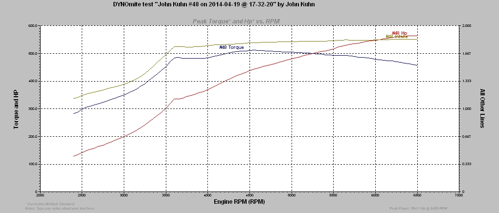
Here's the data on the hot side and the clean version of the dyno graph that looks a little bit like the Capetown Table Top mountain:
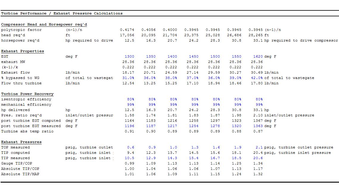
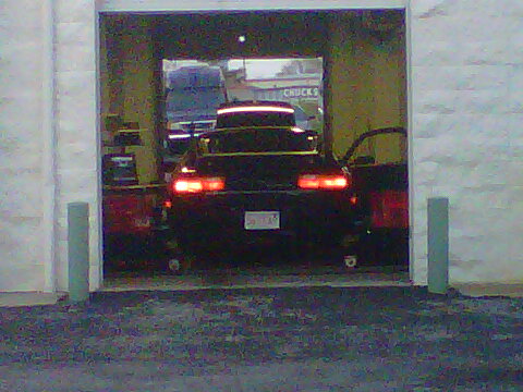
The hot side is working really well and the exhaust at the turbine outlet has a low back pressure. Nothings ever free, of course. The cost of the low exhaust back pressure is demonstrated by the neighbors' kids below:

The plan for tomorrow is to...

I was able to crunch the numbers on the 12 psi run.
Here's the data on the hot side and the clean version of the dyno graph that looks a little bit like the Capetown Table Top mountain:
The hot side is working really well and the exhaust at the turbine outlet has a low back pressure. Nothings ever free, of course. The cost of the low exhaust back pressure is demonstrated by the neighbors' kids below:
The plan for tomorrow is to...
Last edited by ptuomov; 04-24-2014 at 09:23 PM.
04-24-2014, 10:52 PM
#814
Nordschleife Master
Thread Starter
629 rwhp, 112-115K rpm on the turbine shaft, 6350 rpm engine speed, 2.01 bar absolute intake manifold pressure, 2.4 bar absolute exhaust manifold pressure. Still with a flat boost profile, a quick sweep over the rpm range.
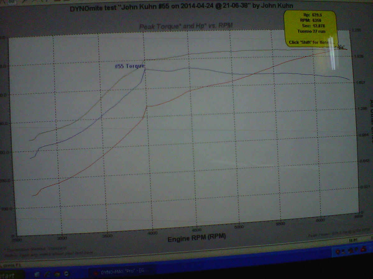
Also, here's an indication of the hot side being just right. With constant boost, we get almost no drop in the high rpm torque, unlike with the earlier turbos with which the torque curve started crashing inversely proportionally to rpm at relatively low rpm levels. The price we're paying is minimal, now the 300 ft-lb threshold is crossed at 2700 rpm instead of 2600 rpm, the 400 ft-lb threshold at 3450 rpm instead of 3150, and the 500 ft-lb threshold at 3700 rpm instead of 3550 rpm.
Also, here's an indication of the hot side being just right. With constant boost, we get almost no drop in the high rpm torque, unlike with the earlier turbos with which the torque curve started crashing inversely proportionally to rpm at relatively low rpm levels. The price we're paying is minimal, now the 300 ft-lb threshold is crossed at 2700 rpm instead of 2600 rpm, the 400 ft-lb threshold at 3450 rpm instead of 3150, and the 500 ft-lb threshold at 3700 rpm instead of 3550 rpm.
Last edited by ptuomov; 04-26-2014 at 09:46 AM.
04-27-2014, 12:37 PM
#815
Nordschleife Master
Thread Starter
The time may have come.
Here's where we're now. The good news is that we're making over 500 ft-lbs from 3600rpm all the way to the redline. The bad news is that Microsoft no longer supports this operating system on that PC. On balance, the good news outweigh the bad news.
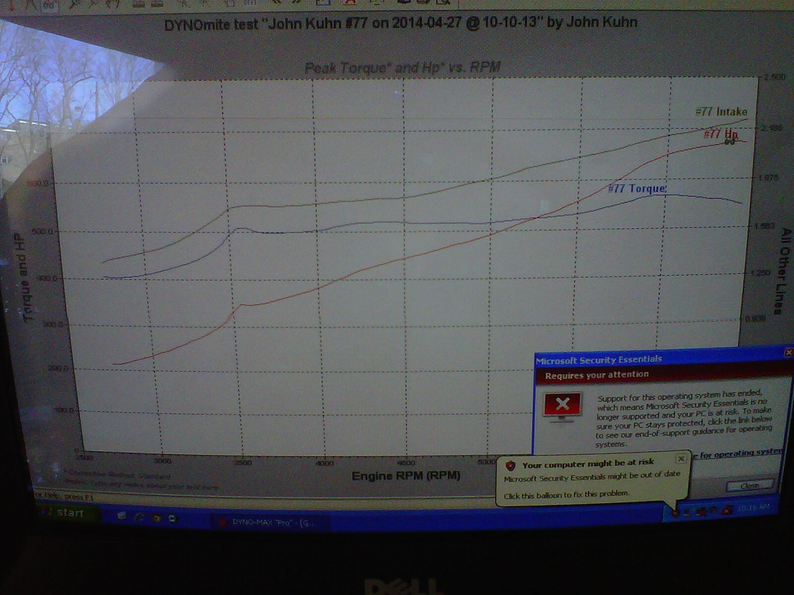
This is produced with a simple, linear boost correction factor (FAC functionality) that begins to increase boost after 4500 rpm. That's a quick and easy method at this point. The final tune will be done with the rpm-specific boost profiles (rSP functionality) which allows for a separate boost level for each 500 rpm step. The rpm specific boost profile will allow us to bandaid over the chocking cams a little bit more at 6500 rpm.
At this point, we're running out of the stock map ranges and we don't have the grid points where we need them. JDS will be getting an email soon.
Overall, the conclusion is that it's difficult to get meaningfully more than 700 rwhp from a completely stock 87 S4 9.4:1 compression motor on 93 octane pump gas and without any meth/water injection. The tune is not optimized and there may be some small hardware tweaks we can make, but there's no "game changer" that we know of that would take us to a whole another level. One either needs to increase the fuel octane or spin the engine to much higher rpms. If the plan would be to stay with the stock engine, then the gt3071r's that I had on there would be the right turbos.
Here's where we're now. The good news is that we're making over 500 ft-lbs from 3600rpm all the way to the redline. The bad news is that Microsoft no longer supports this operating system on that PC. On balance, the good news outweigh the bad news.
This is produced with a simple, linear boost correction factor (FAC functionality) that begins to increase boost after 4500 rpm. That's a quick and easy method at this point. The final tune will be done with the rpm-specific boost profiles (rSP functionality) which allows for a separate boost level for each 500 rpm step. The rpm specific boost profile will allow us to bandaid over the chocking cams a little bit more at 6500 rpm.
At this point, we're running out of the stock map ranges and we don't have the grid points where we need them. JDS will be getting an email soon.
Overall, the conclusion is that it's difficult to get meaningfully more than 700 rwhp from a completely stock 87 S4 9.4:1 compression motor on 93 octane pump gas and without any meth/water injection. The tune is not optimized and there may be some small hardware tweaks we can make, but there's no "game changer" that we know of that would take us to a whole another level. One either needs to increase the fuel octane or spin the engine to much higher rpms. If the plan would be to stay with the stock engine, then the gt3071r's that I had on there would be the right turbos.
Last edited by ptuomov; 05-04-2014 at 05:00 PM.
05-01-2014, 11:27 AM
#816
Nordschleife Master
Thread Starter
We're waiting for two sensors and are investigating the new software from JDS. No interesting new dyno results. Some thoughts on duct sizing below, however.
Here's a purely hypothetical example of how we think about ducting sizes. Remember, we're clearly space constrained.
First thing to note is that the cold side volumes and flow rates are such that bigger is almost always better within the plausible range. Obviously bigger is always better before the compressos. Some very simple computations make it clear that within the relevant range, bigger is also better for the pipes between the compressor and the intake manifold. The benefit of the intake manifold seeing a higher boost at lower rpms usually overwhelms any cost or lag from pressuring the larger pipes. The driver will perceive a sharper responding and less laggy car with larer intercooler pipes. Now, lag's not a problem with a 5.0L engine running stokc cams anyway, just making the point that the effect goes in the opposite direction from what is often claimed.
Air cleaner sizing is one important question. Suppose we want to produce 1000 rwhp, I am pikcing that just as a round number. With the 928 manual driveline, we need about 1150 hp at the crank to produce 1000 rwhp. 1000 rwhp will therefore require about 3000 kg/h of air, or 1500 kg/h per side. That's 683 SCFM or 322 liter/second per side. The air cleaners we currently have flow 352cfm with 1.5" of h2o loss. A good guess of the pressure loss at 683 SCFM is about 6" of h2o or 0.22 psi. That's not ideal, but it's not a big deal either either. If push comes to shove, these air cleaners have headroom. At 500 rwhp level, we should be looking at something like 0.1 psi loss from the air cleaners.
How does dual 2.75" OD compressor inlet pipe work in the 1000 rwhp case? Let's assume 2.75" OD 1/16" wall = 2.625" ID = 66.7mm or rounding it 67mm = 0.067m. The cross-sectional area is 0.067^2 x 3.14159 / 4 = 0.003525 m^2. Flow speed is then 0.322 m^3/s / 0.003525 m^2 = 91.3 m/s or 300 fps.
Wow, that would be fast!
Flow pressure losses are approximately proportion to the "velocity pressure". Density of air at standard temperature and pressure is 1.2 kg/m^3. The velocity pressure is then VP = 0.5 x rho x V^2 = 0.5 x 1.2 x 91.3^2 = 5001 Pa. With standard atmospheric pressure being 101,325 Pa, this is 5% of the atmospheric pressure. If we get that velocity pressure to the compressor inlet undisturbed, the compressor can recover it into static pressure (or at least the compressor map already reflects its inability to do so).
As a crude approximation, every 90 degree elbow is a loss of about 1/4 times the velocity pressure. Every pipe-diameter length is a loss of about 0.02 times the velocity pressure. An entrance from a plenum into the pipe without any particular effort paid to smoothing the entrance will lose around 1.5 velocity pressures. The smoothest possible entrance must lose at least 1.0 velocity pressures because total pressure = velocity pressure + static pressure, but that's theoretically recovered in a gradual diffuser.
Now, let's say we have 5 feet of pipe, which is about 1.5 meters. Say 22.4 pipe diameters. Loss per pipe diameter is 0.02 velocity pressures, so this is 0.45 velocity pressures. Say we have five 90 degree bends = 1.25 velocity pressures. This is in total 1.7 velocity pressures. The total predicted flow loss from the inlet pipes is 1.7 x 5001 Pa = 8500 Pa or about 1.23 psi. In addition, since we are measuring the static pressure only, we also lose one whole velocity pressure, so it's 1.96 psi measured vacuum. Add the air filter predicted pressure loss to this, and at 1000 rwhp we should see about 2.18 psi pressure drop. That's a bit high, so dual 2.75" inlet pipes with many bends may struggle to produce 1000 rwhp.
If you do the same math at 500 rwhp level, we get air cleaner loss of about 0.1 psi, flow velocity of 45.6 m/s, velocity pressure of 1250 Pa, and predicted pressure loss in the pipes of 0.36 psi or combined pressure loss of 0.46 psi. This is well within acceptable limits, which is no surprise as the system was designed for 600-700 rwhp power levels.
05-01-2014, 12:12 PM
#817

Will that software only work in XP? Its time for someone to move off of XP if so.
 05-01-2014, 03:18 PM
#819
Administrator - "Tyson"
Lifetime Rennlist
Member
Lifetime Rennlist
Member
A good tuner can absolutely find the exact limits of an engine without doing any damage to it.
This is especially true if you have a brake equipped dyno.
05-01-2014, 03:24 PM
#820
Nordschleife Master
Thread Starter
I agree that a good tuner can do it safely. However, it involves inducing a slight amount of knock and pulling back one way or the other when the knock starts. I don't know of any other way.
05-01-2014, 03:51 PM
#821
05-01-2014, 03:52 PM
#822
05-01-2014, 03:57 PM
#823
Nordschleife Master
Thread Starter
05-01-2014, 11:01 PM
#824
I see it now. Didn't see it at first.
Ms released one out of band update for Explorer on xp, but that's it.
Ms released one out of band update for Explorer on xp, but that's it.
05-01-2014, 11:41 PM
#825
Inventor
Rennlist Member
Rennlist Member
At this point, we're running out of the stock map ranges and we don't have the grid points where we need them.
The tune is not optimized and there may be some small hardware tweaks we can make, but there's no "game changer" that we know of that would take us to a whole another level.
The tune is not optimized and there may be some small hardware tweaks we can make, but there's no "game changer" that we know of that would take us to a whole another level.
IIRC, the stock EZK load signal from the LH is maxed out above ~200 hp or so, IE. it's pretty much useless unless you can compress the MAF/RPM calculation somehow.
If/when I boost my S4, I plan on looking into replacing the LH load frequency with a frequency based MAP sensor.