
Cruise Control Mod for LED Brake Lights
 09-28-2011, 03:04 AM
#16
Addict
Rennlist Member
Rennlist Member
(Note: terminal numbers, fuse numbers, module locations, etc. referenced in this post are with respect to my '90 S4 and may be different on other model years)
Over the last few days, I spent some time figuring out what was going on with the cruise control module / LED brake light interaction. Got a solid-state solution working, too, but I'm going to hold off on sharing details on that circuit until I make a few more safety and reliability-related revisions (and I have some questions about that and would like to get some opinions).
First, a little background. I've been running LED brake lights for a long time and�thanks to you, Barry�discovered that my cruise control no longer worked (I rarely ever tried to use it and hadn't noticed its absence when you first posted this thread back in 2009!) Once I noticed that, on the rare occasions where I wanted to have the cruise control working (like on longer road trips), I'd just temporarily swap in an incandescent bulb in the CHMSL.
As I mentioned a few posts back (and a couple of weeks ago), I was thinking about this again and wanted to tackle this problem on my own car.
Now... the interesting thing is that I first tried your solution, Barry, although I really wanted to follow up with a non-relay based solution. I looked at what you had done, and when I had the CC unit apart and followed the traces, everything made sense. But... it didn't work for me.
So, I started digging into everything a little more: checking voltages at terminal 8 ("stoplight" signal, +12 V when brake applied, and originally probably close to 0 V when brake not applied: "ground through all the brake bulb filaments", but�after switching to LEDs�kind of floaty or maybe dominated by something going on in the bulb controller). I'd hate to admit how much time I wasted trying different things to no avail (lots of CC removal/tweaks/etc. incandescent bulbs in/out/etc.), but I finally decided to probe all of the terminals on the CC unit and compare to the diagnostic information in the WSM (pp. 27-21 through 27-23). That in itself didn't reveal anything particularly interesting except I noticed something:
Terminal 8 isn't just wired to BK/RE wire "stoplight", but it's also wired via a WT wire to an actuator clutch.
Aha! Terminal 8 is also the return side of the actuator clutch! If there's not a reasonably low resistance return path to ground, that clutch won't work.
Armed with that information, I tried hooking up a quick-and-dirty prototype (solid state, but it could have been a simple relay) that:
Voila! It worked!
In summary, based on my findings, both the CCU itself (via its terminal 8) and the CC actuator clutch (via the WT wire attached to terminal 8) need a low-resistance path to ground for the CC to operate.
So, I've got my car working with an "outboard" solid state solution attached at the CCU connector. I'm going to hold off on sharing the details until I can make a few more refinements.
I do have some questions, though:
(Observation: using a suitable load resistor across, i.e., electrically in parallel with one of the brake light socket wires to address the cruise control problem is a simple, inexpensive, safe, and reliable fix that preserves the safe failure modes designed into the cruise control by Porsche. It's crude, but safe, as long as you're careful to mount the resistor such that it doesn't melt or burn anything when it gets hot. This option has regained some appeal with me when I consider the safety and complexity issues.)
Some interesting tidbits:
Finally, a few photos:
How to "prototype while driving": (this works, but is a slightly different circuit than what I'm using now)

What I'm using now (except I added one more resistor after I took these photos):


Where the new adapter module lives now: right under the CC module connector (and it's barely larger than the connector itself) (note: the CC module lives under the dead pedal on my '90 S4; the dead pedal is rotated around to reveal the CC module in this photo)

Over the last few days, I spent some time figuring out what was going on with the cruise control module / LED brake light interaction. Got a solid-state solution working, too, but I'm going to hold off on sharing details on that circuit until I make a few more safety and reliability-related revisions (and I have some questions about that and would like to get some opinions).
First, a little background. I've been running LED brake lights for a long time and�thanks to you, Barry�discovered that my cruise control no longer worked (I rarely ever tried to use it and hadn't noticed its absence when you first posted this thread back in 2009!) Once I noticed that, on the rare occasions where I wanted to have the cruise control working (like on longer road trips), I'd just temporarily swap in an incandescent bulb in the CHMSL.
As I mentioned a few posts back (and a couple of weeks ago), I was thinking about this again and wanted to tackle this problem on my own car.
Now... the interesting thing is that I first tried your solution, Barry, although I really wanted to follow up with a non-relay based solution. I looked at what you had done, and when I had the CC unit apart and followed the traces, everything made sense. But... it didn't work for me.
So, I started digging into everything a little more: checking voltages at terminal 8 ("stoplight" signal, +12 V when brake applied, and originally probably close to 0 V when brake not applied: "ground through all the brake bulb filaments", but�after switching to LEDs�kind of floaty or maybe dominated by something going on in the bulb controller). I'd hate to admit how much time I wasted trying different things to no avail (lots of CC removal/tweaks/etc. incandescent bulbs in/out/etc.), but I finally decided to probe all of the terminals on the CC unit and compare to the diagnostic information in the WSM (pp. 27-21 through 27-23). That in itself didn't reveal anything particularly interesting except I noticed something:
Terminal 8 isn't just wired to BK/RE wire "stoplight", but it's also wired via a WT wire to an actuator clutch.
Aha! Terminal 8 is also the return side of the actuator clutch! If there's not a reasonably low resistance return path to ground, that clutch won't work.
Armed with that information, I tried hooking up a quick-and-dirty prototype (solid state, but it could have been a simple relay) that:
- takes as input the BK/RE wire originally wired to CCU terminal 8 as input
- completes a very low resistance (< 1 Ω) path to ground to terminal 8 (still also wired to the actuator clutch via the WT wire, but no longer the BK/RE wire).
Voila! It worked!
In summary, based on my findings, both the CCU itself (via its terminal 8) and the CC actuator clutch (via the WT wire attached to terminal 8) need a low-resistance path to ground for the CC to operate.
So, I've got my car working with an "outboard" solid state solution attached at the CCU connector. I'm going to hold off on sharing the details until I can make a few more refinements.
I do have some questions, though:
- Barry, did you do anything else cruise control related other than what you mentioned in post #1 in this thread? I just don't understand how your CC actuator clutch is working given your modification as you described it. Is it possible that (IIRC) your bulb controller modifications might have impacted the path to ground for the CC actuator clutch?
- Big safety/reliability question: If my understanding of the CCU operation is correct, Porsche designed it to be very safe with respect to potential failures. Note that, for example, if you cut the BK/RE wire to terminal 8, the CC will disengage. If you short the BK/RE wire to terminal 8 to ground, the CC will also disengage next time you hit the brakes (if for no other reason than fuse #35 will blow, taking out both the brake lights and the cruise control). If you cut the white wire to the CC clutch actuator, the CC will disengage. Basically, when various "external things" fail, the CC will fail safely. However... with the kinds of modifications that both Barry and I have made... I can see failure modes that would result in the CC remaining engaged. Barry, I'm pretty sure you're using normally-closed relay contacts: when it's not energized, the CC is allowed to engage. So... what happens if that relay fails (i.e., stoplight signal comes in on terminal 8, but relay contacts don't open)? CC is allowed to continue operating, right? Not a good failure mode (unless the CC actuator clutch saves the day, but I still don't understand how it's working given the modification you described). In my case, I'm still not satisified with my design; I can see failure modes (like MOSFET failing with source-to-drain short) that result in the CC remaining active despite stoplight signal going high. So... my question is: how much should we worry about these failure modes? Is it enough to protect the hell out of a MOSFET (zener/TVS clamps etc.) and avoid relays (that might not energize or might stick open or closed), or is it essential to provide a really stright-line path from a "brake" signal to one or more CC disengaging devices (we've got two to pick from, the CCU itself and the CC actuator clutch). If the cruise control doesn't respond to a brake-initiated cancel, there's still always the "cancel" lever; is that enough? I just don't want to bear the burden of possibly introducing the next blizzard of "runaway car"
 stories to hit the evening news.
(Observation: using a suitable load resistor across, i.e., electrically in parallel with one of the brake light socket wires to address the cruise control problem is a simple, inexpensive, safe, and reliable fix that preserves the safe failure modes designed into the cruise control by Porsche. It's crude, but safe, as long as you're careful to mount the resistor such that it doesn't melt or burn anything when it gets hot. This option has regained some appeal with me when I consider the safety and complexity issues.)
Some interesting tidbits:
- CC actuator clutch drain current (CC active, measured via WT return wire): 325 mA
- CCU terminal 8 drain current (CC active): 38 mA
- I once again verified that (at least on my car!, and absent these other cruise control modifications) a 25 Ω load resistor across one of the brake light socket wires won't allow the cruise control to function, but a 6 Ω load resistor will.
Finally, a few photos:
How to "prototype while driving": (this works, but is a slightly different circuit than what I'm using now)

What I'm using now (except I added one more resistor after I took these photos):


Where the new adapter module lives now: right under the CC module connector (and it's barely larger than the connector itself) (note: the CC module lives under the dead pedal on my '90 S4; the dead pedal is rotated around to reveal the CC module in this photo)

Last edited by Ed Scherer; 09-28-2011 at 04:56 PM.
 09-28-2011, 08:48 PM
#17
Electron Wrangler
Lifetime Rennlist
Member
Lifetime Rennlist
Member
Ed with all this - I'd be all over a plain & simple ballast resistor. No worse power than stock and for most folks will also allow operation with the bulb control active & without modification (until you add LEDs for the marker lights too).
Sometimes simple "brute force" methods may not only be easy they may also be the best way...
I commend you for thinking about the failure modes - you can be sure the Porsche engineers always did this for driver safety critical features ...
Alan
Sometimes simple "brute force" methods may not only be easy they may also be the best way...
I commend you for thinking about the failure modes - you can be sure the Porsche engineers always did this for driver safety critical features ...
Alan
09-28-2011, 11:47 PM
#18
Drifting
Thread Starter

Ed,
It's been over two years since I did the mod, so I don't completely follow your writeup. I applogize for that.
My mod is pretty simple. It works by cutting the trace at the brake light (pin 8) and running the trace side to ground through the relay contacts. The relay just serves to interupt the ground when the brake light comes on so that 12V brake light power doesn't short to ground. There is very little current running through the relay (you apparently measured only 38mA). Nothing was done to the bulb control module that would affect this. My bulb control mod only disabled the bulb failure signal to the instrument cluster.
Yes, I did consider failure modes and safety concerns with my mod. I also stated in my first post of this thread, that I couldn't recommend this mod to anyone else and was just documenting what I had done. On the Toyota Unintended Acceleration scare and fatal Camry crash; it still amazes me that a California Highway Patrol officer never thought to put the transmission in neutral.
I think your over rating the Porsche design as fail safe. If the brake light switch fails, the cruise control will be unable to deactivate on its own.
Your implementation looks overly complex to me. When I was working on the solid state solution, I had to cut my losses short when it appeared, it would take more effort than it was worth.
09-30-2011, 07:17 PM
#19
Addict
Rennlist Member
Rennlist Member
Thanks for the responses, guys.
Yeah, I think I'm going to revert mine to the simple resistor soon, even though what I've got works fine during normal operation. It's easy to become really focused on the intellectual challenge of getting something working, but also important to occasionally step back and think about the bigger picture and whether you've really improved something.
It was an interesting exercise and at least now I understand the system much better than before. After this analysis, though, I just don't think it's worth the (probably pretty minimal) risk.
All understood, Barry. And I did note your original disclaimer�and appreciate it and took it seriously enough to dig into more of the subtleties of the way the cruise control system works.
I never said the system as designed by Porsche was "fail safe," I said it was "very safe". Pretty much every aspect of what I looked at, a choice had been made that favored safety over what might have been a little simpler or cheaper. Lots of cases where shorting a wire to ground or cutting a wire will lead to a safe failure. I won't claim that there aren't any single points of failure (and they didn't design and implement a completely dual redundant system), but overall, it's pretty damn well thought out. Even the obvious thing you mentioned: the brake switch itself upon failure will at least trigger a warning light the next time the car is started (the brake light warning light that normally goes out the first time you step on the brake after starting the car). As another example: there could have been a single wire from the controller to power the cruise control actuator clutch (with the other side of that actuator just permanently grounded), but instead they chose to wire the other side to the brake signal, thus deactivating that clutch immediately based on the application of the brake, thus making the clutch disengage through either of the two different pathways. The cruise control and brake lights share a fuse. All of this stuff is pretty smart.
So... all in all, I was noticing a lot of design elements that were well thought out with respect to failure modes, and thus I'd rather not disturb the system in any way that reduces its effectiveness in various scenarios (including component and wiring failures).
Hopefully, I've at least offered more information on how the system works and perhaps some insight into why the system might have been designed the way it was.
BTW, I'd still be curious to know where your actuator clutch is getting its ground (white wire on terminal 8) when the system is activated. Not that it's really that important anymore (I'm done with this now ), but it's the one remaining unanswered question I've got.
And keep posting the info on your mods! It's great to have such a fine community where we're able to share all this stuff.
Ed with all this - I'd be all over a plain & simple ballast resistor. No worse power than stock and for most folks will also allow operation with the bulb control active & without modification (until you add LEDs for the marker lights too).
Sometimes simple "brute force" methods may not only be easy they may also be the best way...
I commend you for thinking about the failure modes - you can be sure the Porsche engineers always did this for driver safety critical features ...
Alan
Sometimes simple "brute force" methods may not only be easy they may also be the best way...
I commend you for thinking about the failure modes - you can be sure the Porsche engineers always did this for driver safety critical features ...
Alan
It was an interesting exercise and at least now I understand the system much better than before. After this analysis, though, I just don't think it's worth the (probably pretty minimal) risk.
Ed,
It's been over two years since I did the mod, so I don't completely follow your writeup. I applogize for that.
My mod is pretty simple. It works by cutting the trace at the brake light (pin 8) and running the trace side to ground through the relay contacts. The relay just serves to interupt the ground when the brake light comes on so that 12V brake light power doesn't short to ground. There is very little current running through the relay (you apparently measured only 38mA). Nothing was done to the bulb control module that would affect this. My bulb control mod only disabled the bulb failure signal to the instrument cluster.
Yes, I did consider failure modes and safety concerns with my mod. I also stated in my first post of this thread, that I couldn't recommend this mod to anyone else and was just documenting what I had done. On the Toyota Unintended Acceleration scare and fatal Camry crash; it still amazes me that a California Highway Patrol officer never thought to put the transmission in neutral.
I think your over rating the Porsche design as fail safe. If the brake light switch fails, the cruise control will be unable to deactivate on its own.
Your implementation looks overly complex to me. When I was working on the solid state solution, I had to cut my losses short when it appeared, it would take more effort than it was worth.
It's been over two years since I did the mod, so I don't completely follow your writeup. I applogize for that.
My mod is pretty simple. It works by cutting the trace at the brake light (pin 8) and running the trace side to ground through the relay contacts. The relay just serves to interupt the ground when the brake light comes on so that 12V brake light power doesn't short to ground. There is very little current running through the relay (you apparently measured only 38mA). Nothing was done to the bulb control module that would affect this. My bulb control mod only disabled the bulb failure signal to the instrument cluster.
Yes, I did consider failure modes and safety concerns with my mod. I also stated in my first post of this thread, that I couldn't recommend this mod to anyone else and was just documenting what I had done. On the Toyota Unintended Acceleration scare and fatal Camry crash; it still amazes me that a California Highway Patrol officer never thought to put the transmission in neutral.
I think your over rating the Porsche design as fail safe. If the brake light switch fails, the cruise control will be unable to deactivate on its own.
Your implementation looks overly complex to me. When I was working on the solid state solution, I had to cut my losses short when it appeared, it would take more effort than it was worth.
I never said the system as designed by Porsche was "fail safe," I said it was "very safe". Pretty much every aspect of what I looked at, a choice had been made that favored safety over what might have been a little simpler or cheaper. Lots of cases where shorting a wire to ground or cutting a wire will lead to a safe failure. I won't claim that there aren't any single points of failure (and they didn't design and implement a completely dual redundant system), but overall, it's pretty damn well thought out. Even the obvious thing you mentioned: the brake switch itself upon failure will at least trigger a warning light the next time the car is started (the brake light warning light that normally goes out the first time you step on the brake after starting the car). As another example: there could have been a single wire from the controller to power the cruise control actuator clutch (with the other side of that actuator just permanently grounded), but instead they chose to wire the other side to the brake signal, thus deactivating that clutch immediately based on the application of the brake, thus making the clutch disengage through either of the two different pathways. The cruise control and brake lights share a fuse. All of this stuff is pretty smart.
So... all in all, I was noticing a lot of design elements that were well thought out with respect to failure modes, and thus I'd rather not disturb the system in any way that reduces its effectiveness in various scenarios (including component and wiring failures).
Hopefully, I've at least offered more information on how the system works and perhaps some insight into why the system might have been designed the way it was.
BTW, I'd still be curious to know where your actuator clutch is getting its ground (white wire on terminal 8) when the system is activated. Not that it's really that important anymore (I'm done with this now
), but it's the one remaining unanswered question I've got.And keep posting the info on your mods! It's great to have such a fine community where we're able to share all this stuff.
09-30-2011, 07:46 PM
#20
Drifting
Thread Starter
Ed,
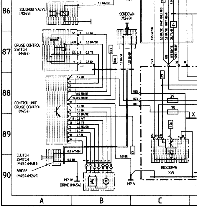
Pin 8 is the brake light signal, so it sees +12V when the brake lights are active. The wiring diagram clearly shows ground to actuator coming from pin 12 on CC controller.

Pin 8 is the brake light signal, so it sees +12V when the brake lights are active. The wiring diagram clearly shows ground to actuator coming from pin 12 on CC controller.
09-30-2011, 07:52 PM
#21
Addict
Rennlist Member
Rennlist Member
I've never dug into the cruise control actuator mechanism, but my mental model for it (based on the signals I see going to it) is that there's an up actuator, a down actuator, and that those are rocking a lever or wheel that is then coupled to the throttle linkage via yet another clutch mechanism, which has its own actuator.
Regardless of the exact construction of the entire cruise control actuator(s) assembly, I know that the white wire that goes to it must see a reasonably low-resistance path to ground to operate. It was sinking about 325 mA through that path when the cruise control is engaged.
09-30-2011, 08:49 PM
#22
Drifting
Thread Starter
Yes, I should have also said that when the brake lights are not active, Pin 8 sees resistance to ground through both the bulb control module and brake lamp filaments which are wired in series.
I've already taken a couple CC actuators apart. They are very simple. The clutch is actually a solenoid which, when engaged, meshes the gears of a gear motor that pulls/releases the tensioned cruise control cable at the throttle console on the side of the intake. The relative cable position is monitored by the potentiometer inside the actuator.
So, to answer your question, with my mod, the clutch actuator apparently has no problem sinking sufficient ground through the bulb control module and LED brake lights. My relay is only sinking the cut trace off pin 8 to ground, which I think you measured as 38mA; it's not seeing the 325mA. I have 7 LED brake lights, so maybe that's why it didn't work for you.
Hope that clears things up. I need to get started on my front seat backrest exchange project, as I found a pair of supple leather seats from an 89' that are the same color (silk grey) as my 90' S4. Should be fun.
09-30-2011, 09:10 PM
#23
Addict
Rennlist Member
Rennlist Member
Yes, I should have also said that when the brake lights are not active, Pin 8 sees resistance to ground through both the bulb control module and brake lamp filaments which are wired in series.
I've already taken a couple CC actuators apart. They are very simple. The clutch is actually a solenoid which, when engaged, meshes the gears of a gear motor that pulls/releases the tensioned cruise control cable at the throttle console on the side of the intake. The relative cable position is monitored by the potentiometer inside the actuator.
So, to answer your question, with my mod, the clutch actuator apparently has no problem sinking sufficient ground through the bulb control module and LED brake lights. My relay is only sinking the cut trace off pin 8 to ground, which I think you measured as 38mA; it's not seeing the 325mA. I have 7 LED brake lights, so maybe that's why it didn't work for you.
Hope that clears things up.
And, BTW, as of a few days ago, I'm running 7 LED brake lights, too, thanks to your thread on that mod. That's a great upgrade, IMHO; among other things, it finally addresses the "relative brightness across brake/parking lights" issue that had been plaguing me (my parking lights were just a little too bright relative to the dim mode of the brake lights).
Cool. Good luck on that! I wish I had a grey interior instead of my "bake-me-every-summer black".
03-23-2015, 01:55 PM
#24
Rennlist Member
Hello Ed or Borland --
I would like to revive this 4+ year old thread. Reason being that now it is 2015 and unfortunately I am unable to view all the pictures/circuit diagrams as many of the images have aged out on Image Shack.
I have the same problem on my 993 --- conversion of all rear brake lights to LED, including CHMSL, yields inoperative cruise control. I am loath to wire in a 6 Ohm 25watt resistor in parallel with the brake lights as I find it somewhat inelegant --- the solid state solution seems very slick.
Would you happen to have the wiring diagrams to recreate any of this -- either the transistor or the relay approach?
FWIW --- I spend 1/2 my week down the hwy from Camarillo in Thousand Oaks for work!
Thanks.
03-25-2015, 01:04 PM
#25
Addict
Rennlist Member
Rennlist Member
Hello Ed or Borland --
I would like to revive this 4+ year old thread. Reason being that now it is 2015 and unfortunately I am unable to view all the pictures/circuit diagrams as many of the images have aged out on Image Shack.
I have the same problem on my 993 --- conversion of all rear brake lights to LED, including CHMSL, yields inoperative cruise control. I am loath to wire in a 6 Ohm 25watt resistor in parallel with the brake lights as I find it somewhat inelegant --- the solid state solution seems very slick.
Would you happen to have the wiring diagrams to recreate any of this -- either the transistor or the relay approach?
FWIW --- I spend 1/2 my week down the hwy from Camarillo in Thousand Oaks for work!
Thanks.
I would like to revive this 4+ year old thread. Reason being that now it is 2015 and unfortunately I am unable to view all the pictures/circuit diagrams as many of the images have aged out on Image Shack.
I have the same problem on my 993 --- conversion of all rear brake lights to LED, including CHMSL, yields inoperative cruise control. I am loath to wire in a 6 Ohm 25watt resistor in parallel with the brake lights as I find it somewhat inelegant --- the solid state solution seems very slick.
Would you happen to have the wiring diagrams to recreate any of this -- either the transistor or the relay approach?
FWIW --- I spend 1/2 my week down the hwy from Camarillo in Thousand Oaks for work!
Thanks.
In post #16 in this thread, you'll see in the "I do have some questions" section a couple of questions. Read question #2 (introduced by "Big safety/reliability question").
The more I thought about the issues I raised there, the more it bothered me to be reducing safety of the cruise control system. I'm just not comfortable encouraging other people to do something that I myself now consider an unnecessary risk. The last thing I want to do is wind up on the news (or courtroom) as somebody involved in the next series of "runaway car" incidents.
03-25-2015, 03:39 PM
#26
Rennlist Member
Howdy, Jason.
In post #16 in this thread, you'll see in the "I do have some questions" section a couple of questions. Read question #2 (introduced by "Big safety/reliability question").
The more I thought about the issues I raised there, the more it bothered me to be reducing safety of the cruise control system. I'm just not comfortable encouraging other people to do something that I myself now consider an unnecessary risk. The last thing I want to do is wind up on the news (or courtroom) as somebody involved in the next series of "runaway car" incidents.
05-29-2016, 04:01 PM
#27
Rennlist Member
Thanks for posting this. I'm going to be revisiting this issue within the next couple of weeks.
I hadn't even noticed that since replacing all my incandescent bulbs with LEDs that I lost my cruise control, since I haven't done any significant road trips since these changes.
I definitely want to address this prior to going to the 2009 OCIC in DFW. Speaking of which, are you going to be there?
I hadn't even noticed that since replacing all my incandescent bulbs with LEDs that I lost my cruise control, since I haven't done any significant road trips since these changes.
I definitely want to address this prior to going to the 2009 OCIC in DFW. Speaking of which, are you going to be there?
I just finished replacing EVERY bulb with LED.
My CC works just fine on a rebuilt brain from Roger.
Update: It worked 2x with lights on, against 10-15 attempts..so..no..no workie.
There are 2 or 3 threads around this...is this "easiest" solved with either a standard bulb as a 3rd brake light, or a resistor?
Trying to marry all of the ways to make everything work right...pull puns on the bulb monitor plug, and the 3rd brake light "fix"...etc.
?
Last edited by Speedtoys; 05-29-2016 at 05:30 PM.
 11-27-2017, 08:15 PM
#29
Electron Wrangler
Lifetime Rennlist
Member
Lifetime Rennlist
Member
11-27-2017, 09:55 PM
#30

