
Resurrecting the porting and polishing by committee thread?
 09-02-2009, 07:12 PM
#61
Nordschleife Master
Thread Starter
---
Cross Sectional Areas in Ports
Measurement Methods and Calculations
� by Harold Bettes
Introduction
It is a common mistake that many engine builders and cylinder head modifiers make when they simply multiply the height of the port times its width. Use of that calculation for area without considering the effect that either an irregular shape or the radii in the corners have on the final answer generates errors in engine program computer simulations, calculations, and evaluations.
The majority of typical ports are somewhat rectangular with various radii used in the corners. This rectangular port configuration is the most common for intake ports while exhaust ports may use the rectangular, square, or variations in most cylinder head applications. Some ports are shaped in a somewhat oval configuration. Some port shapes use the generally rectangular configuration, but have a different radius in each corner and are irregular in shape. Some port configurations might also look a great deal like church windows.
Regardless of the shape of the ports (intake or exhaust), it is possible to measure them and do so accurately. Gaining knowledge of the cross sectional area so that sound decisions concerning port velocity can be used is a reality by application of the methods described in the following sections.
Accurate area measurements of ports, runners, and manifolds are generally very difficult. However, the following methods will assist in making both easy and accurate measurements.
The description of each method of measuring and calculating the port area will also present the conversion to square feet so that it is easy to use with flowbench data which is normally in CFM (cubic feet per minute)
Port Velocity
The mention of port velocity might seem more like a buzz-word to the majority of engine bulders and cylinder head modifiers. The very few that understand and properly apply the knowledge to attain correct and complimentary port velocities are the recipients of some free power and reputations for engines that have superior characteristics (power range - spread from peak torque to peak power).
What is the velocity and how high is too much? A good target velocity in engine operation should be no greater than 55% to 57% of the speed of local sound. This can also be referred to as .55 to .57M. The Mach number references the speed of sound and is named for Ernst Mach (1838-1916). Mach was a physicist, philosopher and early pioneer in studying the speed of sound. The speed of sound is 1087 ft/sec at 32F with an increase of 1.1 ft/sec/F.
The calculation for the speed of sound (Vsound) in ft/sec is approximately:
Vsound ~ 1052 + (1.1 x T), where 1052 = an adjustment constant and T = F.
At this point, note that when considering the airflow of an engine, there is no difference in manifolding, connecting runners, or ports in the cylinder heads, as they are all an extension of the same flowpath. Also note that the various differences in cross sections (areas) allow different local velocities. If we look carefully at the geometry of the flowpath within the engine, it should become apparent that the smallest area will yield the highest local velocity. Evaluating the airflow path of the engine and averaging the lowest velocity with the highest velocity will allow a consideration of average velocity which truly sets the characteristics of the engine, but it is the minimum cross section that establishes the maximum velocity.
Methods of Area Measurement
The area of a square or a rectangle is width (W) times height (H). In the case of a square, both sides are the same, but using the H x W approach will work. The real problem occurs in the corners where there are radii used to form the port of the manifold, runner, or duct in the flowpath.
Because the calculation for the area of a circle is well known, then it can be applied to calculate the equivalent area of either a rectangular or an irregularly shaped port cross section. Even egg-shaped or church window shaped ports can be accurately measured for cross sectional area with this method.
The measurement of the area would be very easy by using a planimeter, but they are very difficult to find and are very expensive if you do find one.
Port (rectangular) Cross Sections - Method 1
It is always easier to evaluate and analyze a problem if you make a sketch. It also assists you in making sure that all the details are allowed for. To calculate the area of a port with the following dimensions H, W, Rcnr. So, the area is (H) x (W) - Acnr = Aprt; where Acnr = Area of corners, Aprt = Area of port (in2). H = height of port, W = width of port. Rcnr x 2 = Dcnr. Dcnr2 x .7854 = Area of circle for the corner radii. The diameter of the circle scribed using the radius of the corners can be placed in a square of the same dimension, the area of the circle subtracted from the area of the square represents the area of the corners (Acnr).
Example - Where the radius of all four corners is the same: Assume for this exercise that the port measurements for height and width and corner radius is known. Where (H = 2.150", W = 1.060", Rcnr = 1/2") .
Step 1) H x W = 2.279 in2
Step 2) Rcnr x 2 = Dcnr = � x 2 = 1
Step 3) Dcnr = 1, so Dcnr2 = 1 x .7854 = .7854in2
Step 4) 1 - .7854 = .2146in2 = Acnr
Step 5) H x W - Acnr = Aprt in2 = 2.279 - .2146 = 2.064in2
Step 6) Aprt / 144 = 2.064 / 144 = .0143ft2
Port Cross Sections - Method 2
The periphery of the cross section can be measured with either a string or stiff wire. By carefully forming the string or stiff wire into all the radii of the corners (even if none are the same) an accurate measurement of that section can be done. Measuring the string or stiff wire provides a length (Cprt). Cprt = pi D, where Cprt = Circumference around the port, pi= 3.1416, and D = an equivalent diameter. When D is found, D2 x .7854 = Aprt in2. Aprt ft2 = Aprt / 144.
Example - A port with 4 different, but unmeasured, radii in the corners is measured with a stiff wire and the resultant length is measured to be 6.3 inches. What is the area of the port at that location?
Cprt = 6.3, so 6.3 / pi = 2.005. D2 x .7854 = (2.005)2 x .7854 = 3.16 in2 = Aprt
Aprt / 144 = Aprt ft2 = 3.16 / 144 = .022ft2
Port Cross Sections - Method 3
This method is sometimes called the "paper doll" method. It uses graph paper cut outs for the different sections to be measured. The preferred graph paper to use is the type that has 10 squares per inch (thus 100 squares per square inch).
The graph paper is cut out so that the graph paper is an image of the port cross section to be evaluated and the squares can be counted. Those squares on the periphery of the cut out that are less than one square are estimated for a value of 1/4, 1/2, or 3/4 of each square for greater accuracy. The total squares are counted and then divide by 100 for the Aprt in square inches. The Aprt / 144 = Asqft.
Example - Graph paper using 100 squares per square inch is used to make a cut out of the port cross section 2" in from the flange surface. The number of little squares counted is 237 (allowing for some around the periphery that were not full squares). What is the area of the port at the location described?
237 / 100 = 2.37in2 = Aprt in2. Aprt / 144 = Aprt ft2 = 2.37/144 = .0165ft2.
Port Cross Sections - Method 4
This method depends upon molds being taken of the port. Various schemes of taking mold impressions have been done for ports, but a favorable process is to use mold maker's rubber (available from several sources). The molds can be sliced into sections at several reference points and then the mold section or "baloney slice" can be placed on graph paper as in Method 3 above and the squares counted and the area is calculated in the same manor.
Port Cross Sections - Method 5
The port can be measured by placing the part (cylinder head, manifold, runner, etc) on a CMM (coordinate measurement machine) unit and the resulting three dimensional "digitizing" of the part can be used to calculate the areas and even volumes and lengths. CMM time is very expensive and measurements from this type approach would be cost prohibitive in normal circumstances.
The use of CNC milling machines for port shaping allows these multiple calculations to be done and supplied with the finished parts. However, this method is not common for normal customers of CNC porting shops because if the shop supplied the data with the cylinder head or manifold, they might be giving away part of their measurement and machining technology as well.
Flowbench Data and Port Area Measurements Provide Local Velocity
As a matter of convenience for this evaluation, SuperFlow flowbenches provide flow data directly in cubic feet of air per minute (CFM). Since we are interested in velocity, it is imperative to know the area of the port. If the port area was expressed in square feet (ft2), then dividing the flow value in CFM by the area in ft2 (square feet) of the port, the result is FPM (feet per minute). Dividing FPM by 60 yields FPS (feet per second). The specific advantage of this method is that it is not invasive (puts nothing in the flowpath) to the port.
Port Velocity Using Flowbench Data and Port Area
Example - Flowbench data = at 25�H2O test pressure of 350 CFM, port area in square feet = .022ft2 (as in Method 2 listed previously) Local velocity at point of area measurement = 350 / .022 = 15909 FPM / 60 = 265.15 ft/sec.
Measurement of Local Velocity with a Pitot Tube
This type of measurement can be done but is fraught with some problems associated with the nature of the Pitot tube itself. The Pitot tube is sensitive to yaw (angle of airstream other than parallel with Pitot tube) relative to the standard direction of the developed flowpath in a port. It is also very difficult to measure the local velocity with a Pitot tube in the vicinity of the "short side radius" (where the flowpath turns from the main stream to the area below the valve). This measurement can be done directly if using a SuperFlow FlowCom with a matching Pitot tube. The indicated local velocity can also be read with a vertical manometer (using the SuperFlow instructions supplied with the Pitot tube).
Measurement of the Effective Flow Area of a Port
This measurement depends upon accurate data from a flowbench and appropriate and complex calculations can be done to establish an effective flow area (EFA, Ae). When the Ae is compared to the physical measurement of the port area in square inches, a correlation can be done to rate the port. The port area is typically measured on a CMM (coordinate measurement machine) with this method. This is another way to rate ports with a Coefficient of Flow (Cf). This methodology is normally used only in the realm of engine designers and engineering personnel assigned to process data for analysis using CFD (computational fluid dynamics).
---
 09-02-2009, 08:25 PM
#62
Rob if you measure the port i.e CC it please leave the valves in. The valves are in when the engine runs as such they need to be in for your measurement.
By Tuomo
Again you are quite correct but here is a bit more information, first some formulas and these formulas and this is where these velocity questions get confusing is some are taken at 28" of water depression and some are in a live engine. The ones I quoted first off are live engine but below 28" some you can calculate from flow bench data. Please read the next quote by Larry Meaux who makes Pipemax
"the Mach # at 350 FPS = approx 350 divided by 1116 thats .3136 Mach ..the 1116 FPS Speed Of Sound depends on local mixture temperature and density
Speed_of_Sound_FPS = (( 459.67 + TempF) * 2402.625624 ) ^ .5 = 1116.32 fps @ 59 F
the FlowBench is steady-state constant depression/velocity and 350 fps = 28" Test Press. approx. but the correlation to Live Engine is that
350 fps at 28" on FlowBench maybe the same as between 614-700 fps
.627 Mach = 700/1116
.55 Mach = 613.8 fps
most People think that just because you FlowTest at 28" inches that everywhere inside that Port air will be flowing at 350 fps...
thats not going to happen unless you have a perfect, constant area, perfectly straight piece of Pipe.
you Calculate what the "baseline Mach Index " was, use the following Formula=>
FPS = ( Bore * Bore * Stroke * RPM * .003537 ) / CSA
CSA = ( Bore * Bore * Stroke * RPM * .003537 ) / 614
Larry M "
So the 28" formulas.
FPS = ( CFM / CSA ) * 2.4
CFM = velocity FPS * CSA / 2.4
CSA = ( CFM / velocity FPS ) * 2.4
So you use max lift flow figure. Mine will be around 315 cfm there for
FPS = ( CFM / CSA ) * 2.4
343.6 = ( 315 / 2.20 ) * 2.4
in metric it is roughly 105 metres. Not that fast when you look below quoting Erland *** however I believe where the difference is is in the ram effect or the inertia fill which is the greater volumetric efficiency. Now there is quite a lot of information dealing with volumetric efficiency of various race engines. F1 engines achieve the highest cylinder fill. In the next post I will just copy and paste a post from someone that was briefed on F1 engines, in particular the Cosworth engine.
"I got it from several places. From the Ilmor SAE paper. From a Pro Stock engine in Pipemax i got 142 m / sec. A 1410 hp prostock engine I just did a valve job on had 135 m / sec. I also checked with a guy who does world championship super sport bike engines and came up with the same velocity. I had the opportunity to test my theories on small 4-valve motorcycle engines.
On these I also tested different angles of approach to the valve for more tumble. I used this formula:
( cylinder volume in cc for one cylinder X max hp RPM X
VE ) / ( 3000 X area in square mm ) = mean inlet velocity in m / sec.
I also calculated velocities past the valves, the valve curtain, farther up in the ports and past the butterflies in the intake to use as a design help. The velocities are very close on good engines."
Erland ***
If I am wrong here please point it out, it is maths is not a strong point of mine.
Greg
By Tuomo
Since you have no turbosuperdupercharger, 700 fps is a mach index of about 0.6 and 750 fps is a mach index of about 0.65. Certainly not slow! ;-) It is my understanding that the sweet spot is at .55 mach before which more speed will generate more ramming than what is lost in additional friction/turbulence/whatnot and after which more speed will lead to bigger increase in friction than what is gained in additional ramming. (It hink I read this on the internet so CAVEAT EMPTOR!) This may be for "average" port and your "straight" may be inherently less subject to friction etc.
The good news that you can always grind more metal off if the torque drops off too early... If you don't meet your goals and if the only problem is too high velocity, you'll see monster torque at mid range. You'll move that torque mountain 500 rpm to the right with a grinder in a weekend!
The good news that you can always grind more metal off if the torque drops off too early... If you don't meet your goals and if the only problem is too high velocity, you'll see monster torque at mid range. You'll move that torque mountain 500 rpm to the right with a grinder in a weekend!
Again you are quite correct but here is a bit more information, first some formulas and these formulas and this is where these velocity questions get confusing is some are taken at 28" of water depression and some are in a live engine. The ones I quoted first off are live engine but below 28" some you can calculate from flow bench data. Please read the next quote by Larry Meaux who makes Pipemax
"the Mach # at 350 FPS = approx 350 divided by 1116 thats .3136 Mach ..the 1116 FPS Speed Of Sound depends on local mixture temperature and density
Speed_of_Sound_FPS = (( 459.67 + TempF) * 2402.625624 ) ^ .5 = 1116.32 fps @ 59 F
the FlowBench is steady-state constant depression/velocity and 350 fps = 28" Test Press. approx. but the correlation to Live Engine is that
350 fps at 28" on FlowBench maybe the same as between 614-700 fps
.627 Mach = 700/1116
.55 Mach = 613.8 fps
most People think that just because you FlowTest at 28" inches that everywhere inside that Port air will be flowing at 350 fps...
thats not going to happen unless you have a perfect, constant area, perfectly straight piece of Pipe.
you Calculate what the "baseline Mach Index " was, use the following Formula=>
FPS = ( Bore * Bore * Stroke * RPM * .003537 ) / CSA
CSA = ( Bore * Bore * Stroke * RPM * .003537 ) / 614
Larry M "
So the 28" formulas.
FPS = ( CFM / CSA ) * 2.4
CFM = velocity FPS * CSA / 2.4
CSA = ( CFM / velocity FPS ) * 2.4
So you use max lift flow figure. Mine will be around 315 cfm there for
FPS = ( CFM / CSA ) * 2.4
343.6 = ( 315 / 2.20 ) * 2.4
in metric it is roughly 105 metres. Not that fast when you look below quoting Erland *** however I believe where the difference is is in the ram effect or the inertia fill which is the greater volumetric efficiency. Now there is quite a lot of information dealing with volumetric efficiency of various race engines. F1 engines achieve the highest cylinder fill. In the next post I will just copy and paste a post from someone that was briefed on F1 engines, in particular the Cosworth engine.
"I got it from several places. From the Ilmor SAE paper. From a Pro Stock engine in Pipemax i got 142 m / sec. A 1410 hp prostock engine I just did a valve job on had 135 m / sec. I also checked with a guy who does world championship super sport bike engines and came up with the same velocity. I had the opportunity to test my theories on small 4-valve motorcycle engines.
On these I also tested different angles of approach to the valve for more tumble. I used this formula:
( cylinder volume in cc for one cylinder X max hp RPM X
VE ) / ( 3000 X area in square mm ) = mean inlet velocity in m / sec.
I also calculated velocities past the valves, the valve curtain, farther up in the ports and past the butterflies in the intake to use as a design help. The velocities are very close on good engines."
Erland ***
If I am wrong here please point it out, it is maths is not a strong point of mine.
Greg
Last edited by slate blue; 09-02-2009 at 10:54 PM. Reason: More info
09-02-2009, 08:31 PM
#63
O.K below is the post I referred to in the above, 145% efficiency, also while my 105 metres a second or 343.6 feet per second doesn't sound much it is much more than the average good race engine, by definition we are meaning push rod V8 engine that has been highly developed. They tend to calculate out at 310 feet per second. So I have upped the ante and only when the engine runs will we know whether that has been successful but as stated to get the volumetric efficiency up it has to run fast.
Greg
I have attached below some notes that I took from an F1 tech conference a while back. The engineer goes into some detail regarding reversion and how they went about dealing with it.
Variable length intake runners:
The runners are constructed of carbon fiber and have a total length in their shortest position of 167mm/6.575in and in their longest 217mm/8.543in. The funnel ID at the extension area is 53.5mm/2.106in. They contain individual throttle plates and they are of an oval shape as opposed to round to better simulate two intake valves next to each other. This provides a better transition into the head. The throttle plates are all controlled individually and this requires a lengthy set-up time to match them all together. The Runners do not travel in one fluid motion through out the rev range instead we opt to make them change directions several times before redline. Because gas dynamics and flow are two separate things we encounter a tremendous amount of pulses within the runner created by the extreme intake tract speeds (up to 200m/sec). This creates wave forms that generate pulses in the opposite direction of port flow. We discovered that you can counter-act much of this by sending the runner back towards it’s long state. During initial testing we found four negative flow pulses during the 10K-18K WOT operation. When the vehicle is coming around a corner from a lower gear under power it will take on average 2-2.5 seconds for the engine to run through it’s range, during that short period the runners must change direction 8 times. Four times to return partially long and four times to return to it’s normal direction. This is done by a very powerful hydraulic system. Due to the reversion that can occur in the intake a dome can be detected coming out of the trumpets at higher revs and this area can rise to � of the diameter of the inlet and must be factored into the runner volume in order for it to be correct. One of the largest issues facing us at that time was air flow and air distribution within the airbox during operation. Because of the pressurization of the box at high speeds we have noticed up to a 10 percent variance in mean effective value from cylinder to cylinder. Variable length runners are now illegal in F1. Because of this there has been experimentation with air boxes with walls that can expand and contract.
Cylinder heads and valve train:
The intake ports are of a mild tumble design with a tumble factor of .7 to .8 and have a flow coefficient of .75. The volumetric efficiency can be up to 145%.The valves are titanium in construction and are angled 12.5 degrees in reference to the engine block deck being 0 degrees. The angle is such that the intake and exhaust valves will both move away from the cylinder wall as they open. The tulip angle or transition from the face to the stem is 12 degrees on the intake and 45 degrees on the exhaust. The shallow angle on the intake valve has been proven to help pull air into and under the valve as it opens. The exhaust valve is ceramic coated and while a small amount comes off during the race it simply exits out the exhaust. This is done because the exhaust can rise to over 1000 degrees Celsius and also contains a steel sleeve in the exhaust port with a small air gap to help keep the head cool. The sleeve is retained by the exhaust flange. The intake valve OD is 40.4mm/1.591in and the exhaust is 33.0mm/1.299in. The intake and exhaust valve stem diameters are 5.5mm/.217in and 6.5mm/.256in respectively. The valve guides do not protrude into the ports and are CNC machined flush. The valve stems have a 0 RA roughness surface finish to protect the valve seals that must contain 10 bar pressure from the pneumatic valve control system. The system is supplied by a 200 bar nitrogen tank that is mounted on the engine during assembly so that it may serve to keep the valves closed. This system is only refilled once every race and will normally last the duration of the race without any problems. In the past this system has frustrated the assembly team because should the system develop a leak, the valves can open and it is very easy to bend one with a revolution of the crankshaft. The pneumatic tappet OD is 31mm/1.220in and the valve lift is 15.5mm/.610in on the intake and 14.1mm/.555in on the exhaust. Using 720 degrees to describe the full engine cycle the intake opening point is 330 degrees and the intake closing point is 640. The camshafts do not ride directly on the tappets instead they utilize a rocker arm that is fixed on one side and the other rests upon the tappet. The guides and seats contain berrilium and some degree of copper. However, the use of berrilium in F1 is now illegal. The intake to exhaust valve percentage is 1.2 but has been experimented with up to 1.7 and during the turbo charging era we ran 1 to 1 valve sizing. The cylinder head deck to cam center height is 141mm/5.551in.
Additional notes
Engine block, rotating assembly, function and design:
The engine block is 90 degree and you can narrow it to 75 degree to satisfy the aerodynamicist without any real change in power. The crankshaft is billet steel and overbalanced with mallory metal. The crankshaft to crankcase clearance is 5mm/.197in. One cylinder capacity is 300cc regardless of wether we are discussing a V10 or the newer V8. The bore is 96mm/3.780in, the stroke is 41.4mm/1.630in. The bore to stroke ratio is 2.32. The piston speed at 18K rpm is 24.8m/sec (4800ft./minute). 18K rpm was determined to be the point of diminishing returns with regards to friction vs. power output. We were already dealing with double the friction of a passenger car engine. Example being 2 bar FMEP (friction mean effective pressure) at 6K rpm of car engine to 4 bar FMEP in F1 engine at 18K. Also, due to the overbalancing we encountered poor harmonics at 8K rpm and these harmonics surfaced again at 21K rpm. In testing the engine would simply break at that rpm. At 8K rpm we would program the engine so that the driver could not operate WOT until 9K. Now they are turning 19K and 20K is not unheard of. But they will likely avoid 21K for some time. The Piston is manufactured by Mahle and is a forged aluminum alloy containing certain amounts of magnesium and berrilium. It is of a two ring design utilizing one top compression ring made of steel and one oil ring. The skirt length is 34mm/1.339in and the piston upper length is 19.5mm/.768in. The piston does contain a pressure relief groove in between the two rings to prevent flutter. Additionally, the top ring vertical clearance is reduced. This caused ring sticking during testing due to expansion and slight carbon build-up in the groove. This was combated by polishing the upper and lower portions of the ring on diamond paper backed with a granite table and a fixture to hold the ring with a .75mm cut-out so that the only thing to contact the table was the 1mm ring. The ring was then polished on both sides until a mirror finish was achieved. This allowed a tighter vertical clearance without sticking in conjunction with Mahle's piston coating. The piston weight is around 250 grams. The piston is full floating with a round wire at each end for pin retention and the wrist pin bushing was bronze with berrilium. The piston pin OD is 21mm/.827in. The piston also had an enclosed area for the centering of the connecting rod side to side clearance. Since the rod was made of titanium it was not allowed to contact the steel crankshaft. This also improved friction losses. Squirters from both ends of the cylinder fire to the under side of the piston for cooling. The piston crown thickness is 5mm/.197in.
The cylinder liners are 3.5mm/.138in thick and contained berrilium and are coated similar to a nickel-sil and have a 0 RA roughness surface finish (mirror like). This in conjunction with only two rings on the pistons and both being of the lowest tension leaves very little oil in the engine at the end of the race. There is two positive displacement pumps at the bottom of the crankcase to remove all oil and they maintain a .5 bar vacuum in the engine at all times. As mentioned the rod is titanium and its center to center length is 113.5m/4.468in. The rod to stroke ratio is 2.7. The wrist pin is pressure fed through the center of the rod. The cap is retained by studs and nuts. The studs are threaded into the rod with a bonding material and then torqued with the cap and the bonding material is allowed a length of time to set-up before the cap is removed. The rod contains strengthening ribs in the big end to beam juncture point since this has proven to be a weak link in the rod from previous tests. The crankshaft is pressure fed oil from the front and the oil will travel through-out the crank to lubricate all rod and main bearings. It is not possible to feed oil to the mains and then rods from individual outside sources because the centrifugal forces are too great. This allowed engine designers to eliminate grooves in main bearings and save weight from both a lighter bearing and a lighter crank. The bearings are of a "plain bearing" design. We tested both plain and roller bearings and found that roller bearings reduced friction greatly up to 8K rpm and the plain bearings reduced friction better above that rpm. The steel backing of the bearing is grooved parallel with the bearing itself to prevent the bearing material from pushing out under load. The material added to the steel backing is of a "spatter" application and is sprayed onto the backing. A traditional tri-metal or aluminum bearing simply would not last in testing. Future trends in this area seem to be leaning towards just applying the spatter application directly to the connecting rod or block instead of making an insert. Compression ratios have varied but seem to fall between 14.3 and 15.0. We have always tried to get as much as possible. With this engine, compression was more important than valve over-lap. Meaning that we would sacrifice less valve pocket for more compression. The compression was always low during build-up but with 1mm/.040in elongation of the titanium rod at 18K rpm it was were we wanted it. The quench clearance is practically 0, it did not touch but it was very close. The valves would elongate .4mm/.016in at 18K rpm so the effective piston to valve clearance is around 2 to 3 tenths of a mm (.008-.012). There is four head studs per cylinder. The ignition timing is usually run between 40 and 42 degrees before TDC. The fuel is usually as a low an octane as we can run legally. Because we need to burn it as fast as possible. Detonation does not exist at 18K rpm we simply "outrun" any negative flame front. The engine will run on pump gas at that rpm, it just makes less power. The water and oil temps ran at 150 degrees Celsius. The air/fuel ratio cannot be revealed because it would then be possible to begin speculating on the fuel blends. However, I can say that some fast burn components such as xylene and toluene are utilized. The lambda readings of the O2 sensor at W.O.T. are .88 to .9 of a volt. With 1.00 lambda/volt being stoichiometric this tells us that while the exact fuel blend may be confidential the blend of that fuel to air is about 10% rich under full throttle.
_________________
- Josh
09-03-2009, 09:10 AM
#64
Nordschleife Master
Thread Starter
Greg --
Instead of guesstimating in my head, I punched your numbers into the Mach index calculator at http://www.wallaceracing.com/machcalc.php. I assumed peak flow of 317 CFM @ max lift 0.650 and 28" of water.
Here's what I got:
"Your bore size is 4.060 inches with a stroke of 3.354 inches and with a valve diameter of 2.15 inches and cross sectional area of 2.20."
"Running a valve lift of 0.650 inches at 7500 RPM, your intake valve mach index is 0.60."
"Running a valve lift of 0.650 inches at 8000 RPM, your intake valve mach index is 0.64"
"The mach index for maximum volumetric efficiency is .5. Beyond .5 the volumetric efficiency falls off. When the MACH Index is near or over .50 it requires a very late Intake Valve closing point. This can be increased by later intake valve closings (60 to 90 degrees ABDC). When Mach Index = .55 to .60 the combination is CHOKED at that RPM."
I don't know whether to believe these numbers, I didn't write the calculator.
This Mach index number is just an indicator. It doesn't take into account cam specifics, for example, when predicting the volumetric efficiency. I think there was a 1979 SAE paper by someone called Wattanabe(?) who estimated that the VE maximizing Mach index depends on the cam aggressiveness, among other things.
What do your pipemax / EAP simulations say about this? EAP computes the actual simulated velocities and not some indicator index, which presumably more accurately predict the volumetric efficiency.
I say you try your heads on as soon as possible to see whether they work or not.
09-03-2009, 10:45 AM
#65
Hi Tuomo, I think your engine program EAP will be much better than Pipemax, remember Pipemax costs $45 The details of my engine are Bore 4.060" Stroke 3.543" Intake valve 2.10" exhaust 1.65". The cams I have are very late closing but I think I will get the custom cams.
As we discussed there are ports and there are ports. The speed quoted is the average, certain parts of the port will be slow and others much faster. As you have said yourself uniform port speed is very important. I have not had the time to see what the speed would be using the formula described by Erland.
I believe this 0.55 Mach number just to be a generalization of what works in most engines, I am sure it would work in my engine but I will not get much over 100% efficiency if I use that number.
Pipemax says that my port will have torque loss due to choke, my people say that is for average ports and that in one of their opinions it would be impossible to choke that port with my combination. He said "How are you going to choke it, it is basically straight, I have only seen one other port like that and it was a Pro Stock bike engine." These engine btw achieve 3.6 hp per CI or if a 928 engine around 1100 hp for 5.0 litres.
If I remember correctly they are 91 cubic inches and rev to around 14,000 rpm and have an almost identical flow curve as my head. Their cams go to 0.835".
Lift--- cfm Modified Stock Lift cfm Percentage Pro Stock Bike Head
0.050" 30 ---------------- 0.050" 26 15% gain------------0.050"
0.100" 64 -----------------0.100" 54 19% gain------------0.100"
0.200" 135 --------------0.200" 111 22% gain------------0.200" 117
0.300" 202 --------------0.300" 159 27% gain------------0.300" 195
0.400" 251-------------- 0.400" 193 30% gain------------0.400" 260
0.500" 288-------------- 0.500" 212 36% gain------------0.500" 295
0.600" 311 --------------0.600" 217 43% gain------------0.600" 313
0.700" 322---------------------------------------------------0.700" 321
0.800" 326---------------------------------------------------0.800" 322
0.900" 326---------------------------------------------------0.900" 321
1.000" 327----------- No higher lift figures available
The ports are similar so are the flow numbers maybe they are related? Anyway fast ports, from what I have read and been told, when a port chokes it will be sonic in one or more parts of the port. This stops anymore speed, so when the air needs to go around a corner it will have different air speeds this is what I believe to instigate the choke, so when you have a port that doesn't have a corner to speak of it should be able to run faster.
I think that the Helmholtz pulses also come into play in doing some of the work of moving the air. They are sound waves as such should be moving at the speed of sound albeit effected by the temperature of the air.
The engine will take a while, I have many things on my plate but I have a great manifold planned, very straight and it should have a taper. Its curve looks like a 997 GT2 manifold's. This is perfect for my port design.
Cheers Greg
09-10-2009, 05:15 PM
#66
Nordschleife Master
Thread Starter
Here are some measurements for the port runners. This is for modiefied S4/GT/GTS heads with original casting revision *.4R. The port is only very slightly bigger than the stock *.4R port.
Location, Intake hor, Intake ver, Exhaust hor, Intake ver.
Seat @ 45 1.405 1.405 1.276 1.276
Insert bore 1.250 1.250 1.146 1.146
Bowl 1.275 1.275 1.176 1.176
At guide 1.315 1.170 1.170 1.175
Throat 2.130 1.336 1.810 1.460
Port opening 1.960 2.013 1.610 1.610
All numbers are in inches, the first column of numbers per port is the "side to side or horizontal" measurements of the port runner the column of numbers per port is the "up and down or vertical" measurements. For area comparisons, one can assume ovality for intake and exhaust throats and intake port opening.
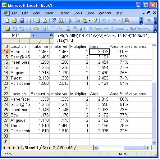
EDIT: Here with approximate cross-sectional areas. I assumed two halves of a circel and a rectangle between them. The Excel formula I used is =(PI()*((MIN(J14,K14)/2)^2)+ABS(J14-K14)*MIN(J14,K14))*L14.
Location Intake hor Intake ver Multiplier Area Area % of valve area
Valve face (std) 1.457 1.457 2 3.333 100%
Seat @ 45 1.405 1.405 2 3.101 93%
Insert bore 1.250 1.250 2 2.454 74%
Bowl 1.275 1.275 2 2.554 77%
At guide 1.315 1.170 2 2.490 75%
Throat 2.130 1.336 1 2.463 74%
Port opening 1.960 2.013 1 3.121 94%
Location Exhaust hor Exhaust ver. Multiplier Area Area % of valve area
Valve face (+1mm) 1.339 1.339 2 2.815 100%
Seat @ 45 1.276 1.276 2 2.558 91%
Insert bore 1.146 1.146 2 2.063 73%
Bowl 1.176 1.176 2 2.172 77%
At guide 1.170 1.175 2 2.162 77%
Throat 1.810 1.460 1 2.185 78%
Port opening 1.610 1.610 1 2.036 72%
Location, Intake hor, Intake ver, Exhaust hor, Intake ver.
Seat @ 45 1.405 1.405 1.276 1.276
Insert bore 1.250 1.250 1.146 1.146
Bowl 1.275 1.275 1.176 1.176
At guide 1.315 1.170 1.170 1.175
Throat 2.130 1.336 1.810 1.460
Port opening 1.960 2.013 1.610 1.610
All numbers are in inches, the first column of numbers per port is the "side to side or horizontal" measurements of the port runner the column of numbers per port is the "up and down or vertical" measurements. For area comparisons, one can assume ovality for intake and exhaust throats and intake port opening.
EDIT: Here with approximate cross-sectional areas. I assumed two halves of a circel and a rectangle between them. The Excel formula I used is =(PI()*((MIN(J14,K14)/2)^2)+ABS(J14-K14)*MIN(J14,K14))*L14.
Location Intake hor Intake ver Multiplier Area Area % of valve area
Valve face (std) 1.457 1.457 2 3.333 100%
Seat @ 45 1.405 1.405 2 3.101 93%
Insert bore 1.250 1.250 2 2.454 74%
Bowl 1.275 1.275 2 2.554 77%
At guide 1.315 1.170 2 2.490 75%
Throat 2.130 1.336 1 2.463 74%
Port opening 1.960 2.013 1 3.121 94%
Location Exhaust hor Exhaust ver. Multiplier Area Area % of valve area
Valve face (+1mm) 1.339 1.339 2 2.815 100%
Seat @ 45 1.276 1.276 2 2.558 91%
Insert bore 1.146 1.146 2 2.063 73%
Bowl 1.176 1.176 2 2.172 77%
At guide 1.170 1.175 2 2.162 77%
Throat 1.810 1.460 1 2.185 78%
Port opening 1.610 1.610 1 2.036 72%
Last edited by ptuomov; 10-03-2009 at 10:24 AM.
09-10-2009, 06:37 PM
#67
Nordschleife Master
Thread Starter
This is a quote from Erland *** from somewhere else on the web:
When I port 4 valve engines I always have the smallest area in the port just before the valve stem. The diameter is around 80% of the valve size [ptuomov: 80% of diameter, not area]. The seat id I use is up to 90% but not bigger with 45 degree seats. I have never tried steeper seats in these heads. I port a lot of one cylinder Daytona 4-valve engines for mini motards and that gives a good opportunity to experiment. These engines are really expensive, more so than a 4-cylinder so I was a bit causious in the beginning. First I just filled the bowl and floor a little but for each head I have made I have straightenened the intake port more. On the last head I filled the bowl so that the valve guide is completely covered and took lots of material out of the floor. It is now almost as straight as a Ducati port and looks a lot like the Honda drawing above. The port is oval aprroaching the valve as it reaches the valve at an angle. The head was tested on a track yesterday and ran better in all of the powerband used. I can post pictures of the molds, just have to take them. I do not believe in having the smallest port area at the seat in a head with an open combustion chamber like a 4-valve. You loose flow if you do not start to diffuse the flow in the port.
09-10-2009, 07:32 PM
#68
Instructor

I know I have posed a few questions on Landshark regarding temperature of intake air and how it effects the airspeed, but that is correct what you say above. Some points across the port would be sonic and some not albeit the difference in air temperature.
There is an ideal air temp that will bring the highest speed for the greatest density but it is difficult to get and keep constant

Glenn
'81 928
AU
10-04-2009, 11:45 AM
#69
Nordschleife Master
Thread Starter
Moving some of the pure porting stuff here from the 5.0 Screamer thread:
Why do you think Porsche made the ports so big? Not using this as an argument against you, they look large in terms of the air speed, just wondering what the motivation was. And with the 3.0 liter 968 they went with even bigger ports.
In any case, perhaps the following is of some relevance. With a 37mm (1.4567") intake valve, the circumference of the two valves is going to be about 9.15". This means that the curtain area exceeds the 2.42 sqin area only at lifts higher than .264" or 6.7mm. The maximum air speed in the port and thus the inertia effect is going to be due to the valve restriction for a whole lot of the cycle.
Perhaps the motivation by Porsche was to make a cylinder head that they could cam to different engines very easily?
Also the guys that do my work say that to achieve a volumetric efficiency of 105% on a 90 degree port (like a Chevy) you need at least 270 feet per second (@28") of average velocity.
Now if I recall correctly, Erland said that the F1 ports run at over 400 feet per second and while I am giving away secrets he told me that I should run part of my Porsche port at 142 metres a second or 465 feet per second. It will be interesting if his customer can find the photos of that port he did. As for gains, again, trial and error and Erland may know as he has done this.
Now if I recall correctly, Erland said that the F1 ports run at over 400 feet per second and while I am giving away secrets he told me that I should run part of my Porsche port at 142 metres a second or 465 feet per second. It will be interesting if his customer can find the photos of that port he did. As for gains, again, trial and error and Erland may know as he has done this.
In any case, perhaps the following is of some relevance. With a 37mm (1.4567") intake valve, the circumference of the two valves is going to be about 9.15". This means that the curtain area exceeds the 2.42 sqin area only at lifts higher than .264" or 6.7mm. The maximum air speed in the port and thus the inertia effect is going to be due to the valve restriction for a whole lot of the cycle.
Perhaps the motivation by Porsche was to make a cylinder head that they could cam to different engines very easily?
12-09-2009, 06:21 PM
#70
By Ptuomov
Tuomo I just found my exhaust numbers and were your exhaust figures done with a flow pipe? My figures without the pipe are way off. E.g @.500 stock 243 cfm with pipe I am 5 cfm more than you. That difference of 5 cfm would be easily explained by differences in the pipe as there is no uniform standard of testing with a flow pipe except the 90 degree bend in it.
If you didn't test with it, the bench that you used and the one I used are quite different in results.
Greg
All testing is at 28 inches depression.
Stock RMI
Lift Intake Exhaust Intake Exhaust
050 41.9 52.0 48.5 63.9
100 104.7 105.6 110.4 115.2
150 149.2 152.8 153.2 152.7
200 198.3 196.5 201.5 203.8
250 239.2 229.2 244.5 241.7
300 269.6 247.6 280.1 262.1
400 296.9 259.2 312.6 274.4
500 301.0 264.7 320.5 279.7
600 306.1 263.0 322.1 286.2
------------------------------------------------
Avg 233.0 212.8 244.5 225.5
If you didn't test with it, the bench that you used and the one I used are quite different in results.
Greg
08-25-2014, 10:29 AM
#71
Rennlist Member
Join Date: Feb 2011
Location: Mostly in my workshop located in Sweden.
Posts: 2,226
Received 442 Likes
on
244 Posts
Here's something that I came across today. Someone was advocating sinking the exhaust valves in deep in the head/seat and raising the intake valves. The stated logic was to reduce reversion into the intake port while making the exhaust flow better out of the cylinder.
This from a Chevy book ("How to Build and Modify Chevrolet Small-Block V8 Cylinder heads"):
"...I prefer to set the intake valve in the chamber higher than the exhaust valve. With the intake an attempt should be made to produce a valve and seat combination that sits as high in the chamber as possible, whereas I will deliberately sink the exhaust into the head a little way. Just how much the exahust valves can be sunk depends on the individual casting."
"It's usually not practical to sink valves by more than 0.020-0.030 in., and you may very well ask what the logic is for doing so. In essence, this procedure relates to the mechanics of the gas flow during the overlap period. If the intake valve is higher than the exhaust valve, it enhances the tendency for the fresh charge to pass out of the intake valve and over the top of the exhaust valve face rather than under it and on out the exhaust port."
Anybody here made any concious effort to raise the intake valve and sink the exhaust valve?
�ke

