
DIY Oil Separator/Catch Can
 01-24-2009, 04:40 PM
#16
Rennlist Member
 01-24-2009, 04:45 PM
#17
Under the Lift
Lifetime Rennlist
Member
Lifetime Rennlist
Member
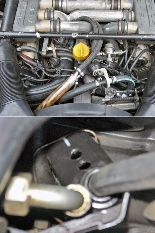
Note also that the bottom filler neck breather has a one-way valve. In the stock configuration this is connected to the intake after the MAF, at least on the later S4 intake. Same with the upper filler neck breather hose. The whole stock configuration bothers me, but the one shown here doesn't.
01-24-2009, 05:06 PM
#18
Rennlist Member
So where would the one-way breather be in the above diagram and which direction would it allow flow?
Last edited by SharkSkin; 01-24-2009 at 09:34 PM.
01-24-2009, 06:33 PM
#19
Inventor
Rennlist Member
Rennlist Member
I just recently made a catch can out of a wide mouth oil container, with two 5/8" holes drilled in it. (I had been dumping right onto the undertray = messy.) I bent a piece of clotheshanger to hold it to the A/C hose.
I always keep my oil level below 1/4 over the 'fill' mark. This reduces oil ejection on the dyno to almost nothing.
I always keep my oil level below 1/4 over the 'fill' mark. This reduces oil ejection on the dyno to almost nothing.
01-24-2009, 08:56 PM
#20
Nordschleife Master
To answer the questions,
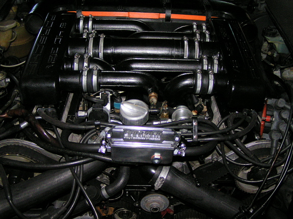
The Minivent, is hooked up to one of the two ports lower on the filler neck, as well as the 2 ports on the cam covers. This allows COMPLETELY free breathing of the crankcase, viat the filter on the top of the minivent. Then you have a line which goes from the top of the filler neck, via the oil/water seperator, into the intake manifold. This you have shown in your pictures as connecting between the valves and the throttle body to provide crankcase vacuum.
The way this is routed produces ZERO crankcase vacuum as it is all being sucked in via the filter on the minivent unit. And as already explained allows unmetered air into the intake manifold.
I hope that is clear enough for everyone to understand.
01-24-2009, 09:02 PM
#21
Nordschleife Master
I don't see where it is being introduced downstream of the MAF in his configuration.
Note also that the bottom filler neck breather has a one-way valve. In the stock configuration this is connected to the intake after the MAF, at least on the later S4 intake. Same with the upper filler neck breather hose. The whole stock configuration bothers me, but the one shown here doesn't.
Note also that the bottom filler neck breather has a one-way valve. In the stock configuration this is connected to the intake after the MAF, at least on the later S4 intake. Same with the upper filler neck breather hose. The whole stock configuration bothers me, but the one shown here doesn't.
The stock system is not good I do agree. But this system is allowing unmetered air into the system which is going to lower the AFR the engine is running at, how much and how much the O2 sensor can compensate noone may really know. But I would change this system around pronto.
01-24-2009, 09:15 PM
#22
Rennlist Member
I have a valve also, 86, at the base of the filler neck, in the line that runs to the front port on the passenger side valve cover, FWIW, on an original non-adulterated car.
I thought it might be a PCV, and if so, if working, the higher the vac, the more it closes?
I thought it might be a PCV, and if so, if working, the higher the vac, the more it closes?
01-24-2009, 11:41 PM
#23
Under the Lift
Lifetime Rennlist
Member
Lifetime Rennlist
Member
I don't see anything going to the plenum except on the driver side, and that has no access to atmosphere. The passenger side, where there is access to atmosphere, goes into the filler neck connector that should have a one-way valve, only allowing air out of the neck.
01-24-2009, 11:47 PM
#24
Under the Lift
Lifetime Rennlist
Member
Lifetime Rennlist
Member
To answer the questions,
The Minivent, is hooked up to one of the two ports lower on the filler neck, as well as the 2 ports on the cam covers. This allows COMPLETELY free breathing of the crankcase, viat the filter on the top of the minivent. Then you have a line which goes from the top of the filler neck, via the oil/water seperator, into the intake manifold. This you have shown in your pictures as connecting between the valves and the throttle body to provide crankcase vacuum.
The way this is routed produces ZERO crankcase vacuum as it is all being sucked in via the filter on the minivent unit. And as already explained allows unmetered air into the intake manifold.
I hope that is clear enough for everyone to understand.
Last edited by Bill Ball; 01-25-2009 at 01:07 AM.
01-25-2009, 12:17 AM
#25
Addict
Rennlist Member
Rennlist Member
That's nice...I did one for $20 bucks a few months back. Gave one to Ken, but his car pukes oil for some reason 
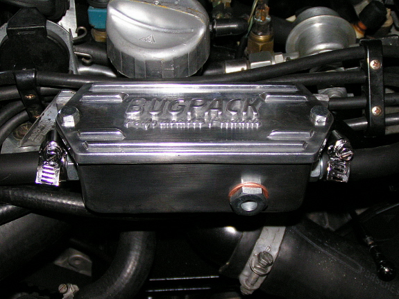
Works like a charm in my 85. No more oil in the throttle body and intakes other than normal expected residue. (*as I puff off a cigar in my easy chair) I rerouted the breather lines and collectors in/from the valve covers. Valve covers are connected together like a GTS. Capped off the T body breather nipples, ran both lines from the oil fill at the crank case right up to the canister. Its the highest point, so anything that might actually collect up there, will run back down to the crank case. Available at any Veedub performance shop.
Works like a charm in my 85. No more oil in the throttle body and intakes other than normal expected residue. (*as I puff off a cigar in my easy chair) I rerouted the breather lines and collectors in/from the valve covers. Valve covers are connected together like a GTS. Capped off the T body breather nipples, ran both lines from the oil fill at the crank case right up to the canister. Its the highest point, so anything that might actually collect up there, will run back down to the crank case. Available at any Veedub performance shop.
01-25-2009, 12:58 AM
#26
Instructor
Thread Starter

Hi everyone,
Thanks for all the comments, I have really enjoyed reading your feeback. It's always helpful to hear others' perspective and constructive criticism on stuff like this.
I did want to respond to the comments about allowing unmetered air into the system. Currently, there is NOT a check valve (PCV) installed in this system. My original plan DID include 2 downstream of the cam cover ports, but I ended up changing my mind after observing the following: At idle, there is a possiblility of a small amount of unmetered being drawn in reverse from the JAZ breather filter. However, in a couple of tests, this proved negligable.
Also, I observed that once the car turned about 1500 RPM or higher, the crank pressure changed from neutral to positive at the JAZ can breather filter. Based on these findings, I concluded that my base idle mixture may be off slightly, but once the pedal is down, pressure is moving in the correct direction. To further verify any possible lean conditions under load, I have "read" my plugs several times only to find them in an optimal mixture state (look).
If anything, I may still install a PCV to control any high suction condition created from throttle-lift which may save my gaskets from blowing. Other than that, I'm planning to spend much less time cleaning up oil from the plenums and more time driving!!!
-Cheers
01-25-2009, 01:14 AM
#27
Three Wheelin'
Join Date: Sep 2006
Location: Banished to the SBC Wastelands
Posts: 1,578
Likes: 0
Received 4 Likes
on
3 Posts
So it looks like the 16v's would benifit from the "Husky" mod as well. In line between top of oil fill and where it returns to the bottom plenum right before the TB. Bit cheaper than Carl's though not as clean looking. Nice.
01-25-2009, 02:22 AM
#28
Rennlist Member
 01-25-2009, 11:48 AM
#29
Rennlist Member
I have done similar, but went a couple steps beyond. I upgraded my breather setup to GTS configuration then added an in-line 951 oil seperator. I have seen 0 ingestion since. Additionally, at the drain part of the seperator i have seen no oil at all. I would say the first step for the 87-91 cars is to put the GTS configuration.
01-25-2009, 12:47 PM
#30
Rennlist Member

Join Date: May 2008
Location: The other Vancouver
Posts: 197
Likes: 0
Received 0 Likes
on
0 Posts
PorKen,
Are you using the PVC valve and do you have both cam cover ports capped? Do you use a baffle at the bottom of the oil filler neck?
Thanks.
Tony
Are you using the PVC valve and do you have both cam cover ports capped? Do you use a baffle at the bottom of the oil filler neck?
Thanks.
Tony