
'87 Intake Removal, Repairs, Installation Procedure (w/pics)
 02-06-2009, 11:09 PM
#136
Rennlist Member
Thread Starter
Join Date: Sep 2007
Location: Ridgecrest, California
Posts: 1,363
Likes: 0
Received 143 Likes
on
28 Posts
THANKS for the observation on later years not having the sealing rings on the cam covers. I'll edit my original post with this information (seals present primarily on '87, 88). THANKS again!
 02-06-2009, 11:16 PM
#137
Rennlist Member
Thread Starter
Join Date: Sep 2007
Location: Ridgecrest, California
Posts: 1,363
Likes: 0
Received 143 Likes
on
28 Posts
 02-06-2009, 11:28 PM
#139
Addict
Rennlist Member
Rennlist Member
Join Date: Oct 2003
Location: Gone. On the Open Road
Posts: 16,321
Received 1,542 Likes
on
1,006 Posts
What I should have posted is a suggestion that folks taking off their cam covers examine the bolts for the presence or absence of the rings before removing them and note which bolts 'need' rings. The implication is that any bolts that have the rings should be bolted back in place with the rings and bolts without shouldn't need them.
02-06-2009, 11:51 PM
#140
Rennlist Member
Thread Starter
Join Date: Sep 2007
Location: Ridgecrest, California
Posts: 1,363
Likes: 0
Received 143 Likes
on
28 Posts

Ooopps! Was that my outside voice??
I meant to say, she deserves to get something nice out of all the time, effort and $$ I put into these sharks. She loves her sharks and as a result, I continue to expend gobs of time, effort and $$ on them with no resistance from the wifee. Whenever we go somewhere together in one of them, I always drive so I get to enjoy the low mileage sharks too. Everybody's happy! We also have a standing agreement that I can take either one of her's for myself as long as I replace it with one of equal or greater value. She's actually expressed interest in Brian's S4 that's for sale right now.
02-06-2009, 11:59 PM
#141
Rennlist Member
There is reference to the two types of seals it in the 85 Service publications in 2.15 of the CD's, though
Dwayne, my wife commandeered the 86, a gem.
Dwayne, my wife commandeered the 86, a gem.
02-07-2009, 12:03 AM
#142
Rennlist Member
Thread Starter
Join Date: Sep 2007
Location: Ridgecrest, California
Posts: 1,363
Likes: 0
Received 143 Likes
on
28 Posts
Dwayne, my original post on the sealing rings was too vague. There's no documentation AFAIK on which years have rings and which don't. Anecdotal evidence suggests that as the castings for the cam covers got better with the later models years the prevalence of the rings decreased. But, (again AFAIK) no one knows for sure. My '89 had them on one side and not the other. Most '87s I've seen have them on both sides but on seemingly random bolts.
What I should have posted is a suggestion that folks taking off their cam covers examine the bolts for the presence or absence of the rings before removing them and note which bolts 'need' rings. The implication is that any bolts that have the rings should be bolted back in place with the rings and bolts without shouldn't need them.
What I should have posted is a suggestion that folks taking off their cam covers examine the bolts for the presence or absence of the rings before removing them and note which bolts 'need' rings. The implication is that any bolts that have the rings should be bolted back in place with the rings and bolts without shouldn't need them.
02-07-2009, 01:32 AM
#143
Rennlist Member
Thread Starter
Join Date: Sep 2007
Location: Ridgecrest, California
Posts: 1,363
Likes: 0
Received 143 Likes
on
28 Posts
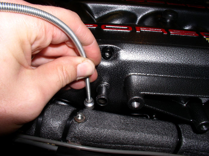
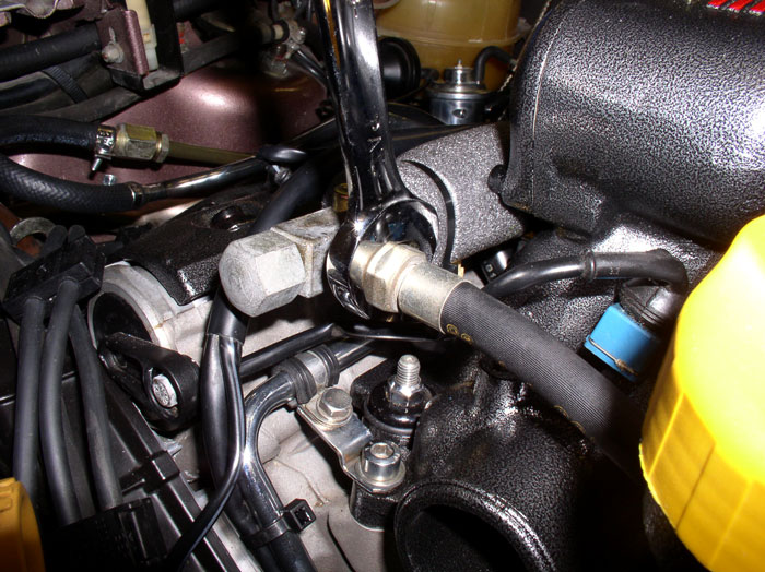
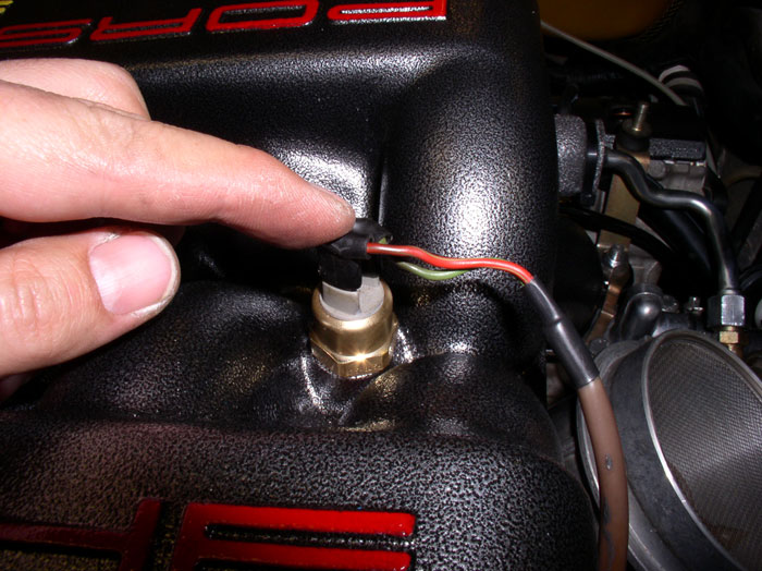
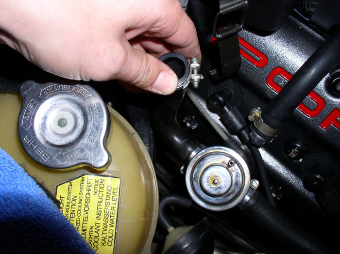
Before getting to work on the fuel rails, I installed the air temperature switch in the top of the plenum. This temperature switch is used (along with inputs from other sensors) to control the front radiator flaps being open/closed and radiator fans.
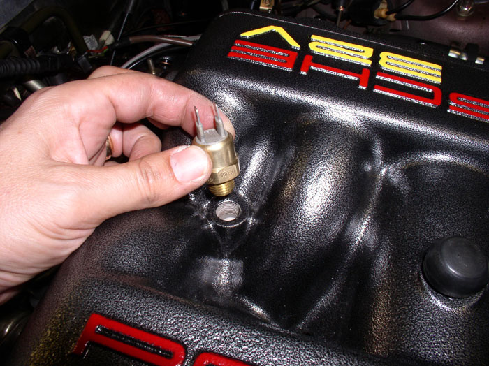
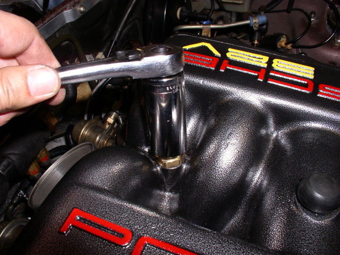
Use a 22mm deep socket to re-install and snug down. I couldn't find a torque value in the manuals but given the ease with which the switch came out, 15 ftlbs seemed sufficient.
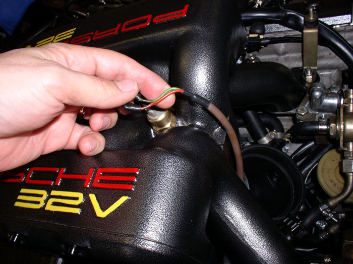
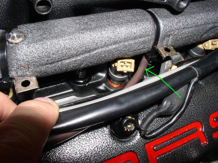
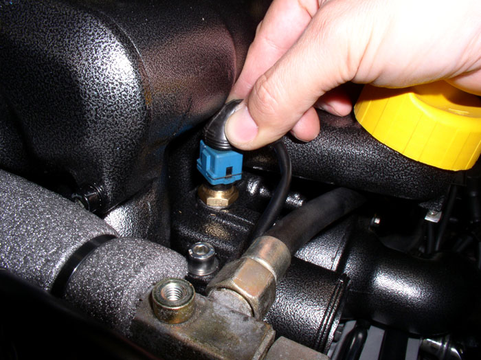
Next, route the harness connection to the temperature switch. Route the wire as shown below between the last two intake runner legs....
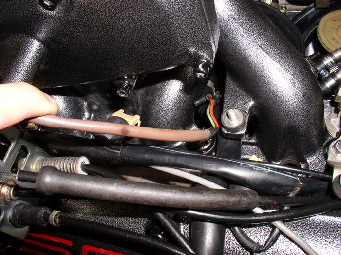
....and up behind the intake. Make sure enough wire is present to connect to the terminals. I did not connect mine to the switch just yet.
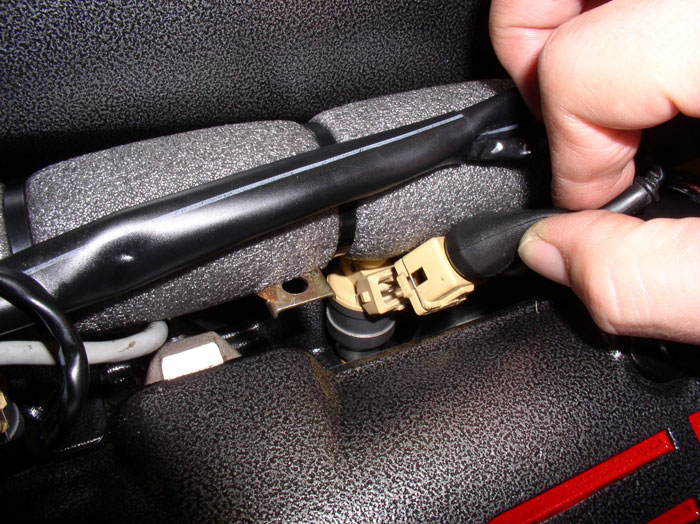
Now for the fuel injectors. If you sent your injectors off or removed them from the fuel rail, now's the time to install the injectors back into the fuel rail. I had my injectors temporarily installed into the intake to prevent debris from entering the head. If you did the same, remove them and install into the fuel rails. It's a good idea to use a lubricant on the upper and lower o-ring seals of the fuel injector. I've used a light coat of motor oil - you can also use another lubricant but ensure it is sensor-safe. Push the top of the fuel injector into the rail until it is fully seated. Orient the fuel injector so that the plug to the harness is facing away from the intake when the fuel rail is mounted (see below).
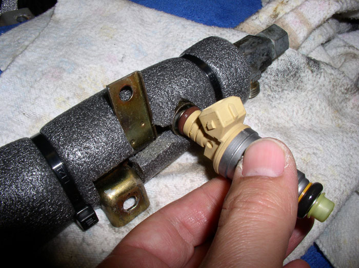
After the fuel injector is in, attach the retaining clip as shown. I oriented the retaining clip in the same manner as they were attached when I took them out.
Attach all four injectors to the fuel rail and then do the same for the other fuel rail.
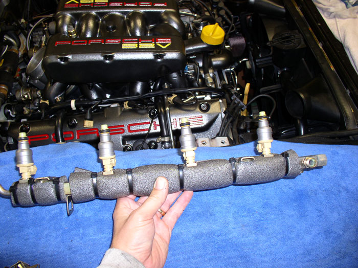
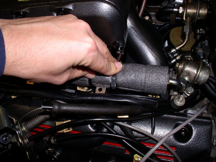
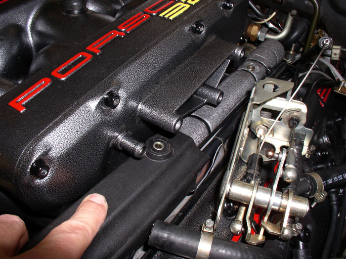
Starting with the driver's side, position the fuel rail with injectors into place. Ensure the ends of the fuel rail line up with the fuel pressure dampers at each end. Also ensure the two mounting brackets on the fuel rail are lined up to fit over the M6 mounting studs on the intake. .
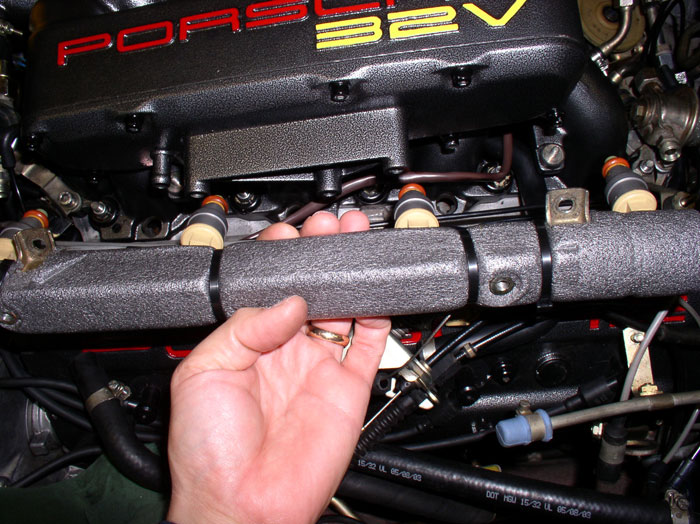
When you lower the fuel rail down into position, ensure the air temperature switch wires harness is routed between cylinders 6 and 7 fuel injectors as shown. Also, it is very important that you ensure each injector is lined up to go into is respective injector hole in the intake. Otherwise, a misaligned injector can result in a cracked pintle cap while pressing the fuel rail down into place.
Then press down on the fuel rail until all four injectors are fully seated. The fuel rail mounting brackets will only allow you to push down so far until the brackets are seated on their M6 studs.
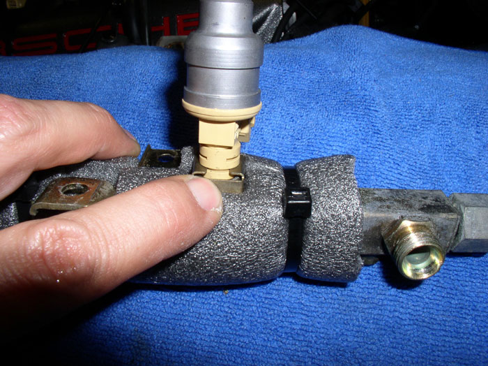
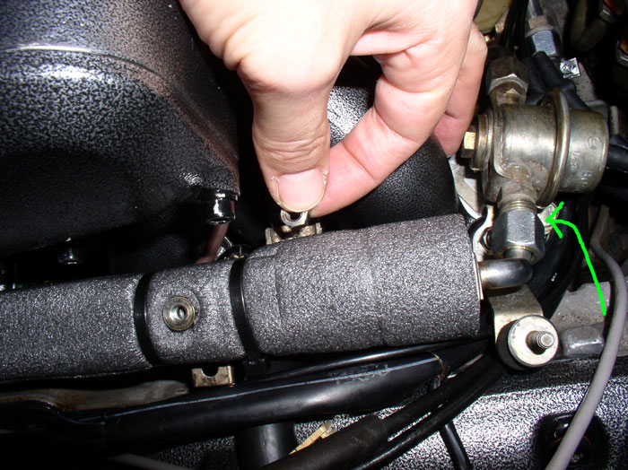
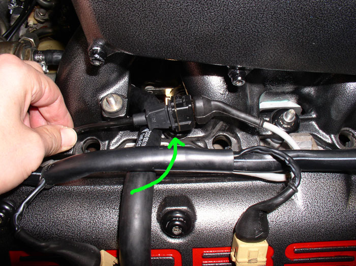
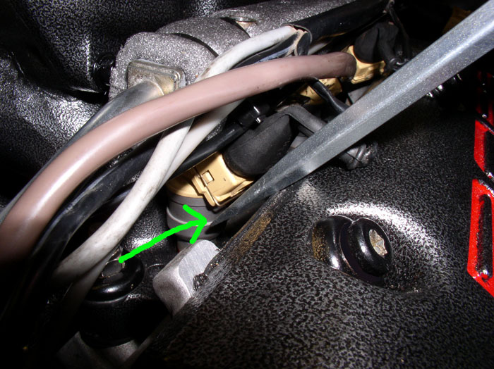
Before installing and tightening down the 10mm nut on the fuel rail mounting brackets, ensure the end of the fuel rail is perfectly aligned with the Fuel Pressure Damper (FPD) receiving end (see green arrow). It is important that the fuel rail is not in a bind as a result of misalignment of the fuel rail connection at the FPDs - otherwise it may lead to leaking seals (vacuum leak) at the fuel injectors. Install the 10mm nut on the fuel rail mounting stud at the rear of the fuel rail.
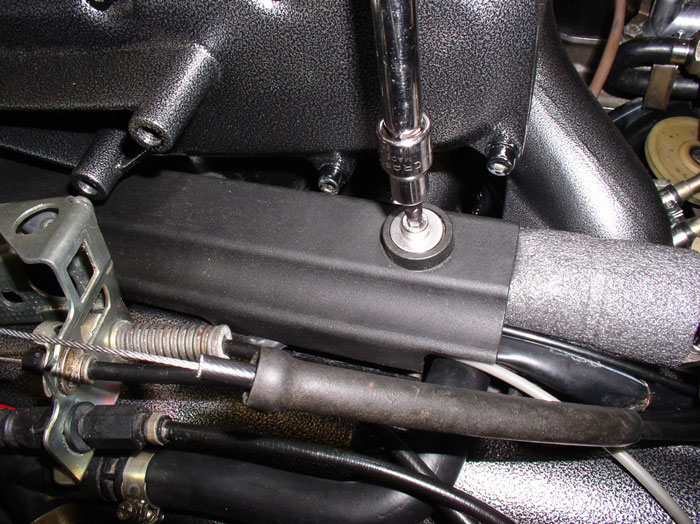
To reach the mounting stud on the front of the fuel rail, I used a magnetic pick-up tool to hold the nut....
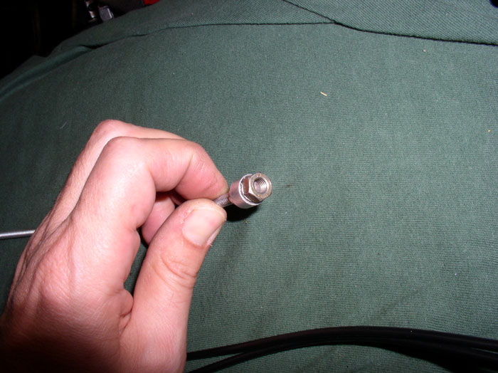
....then placed the nut on the stud and turned the magnetic tool until the nut was started on the threads.
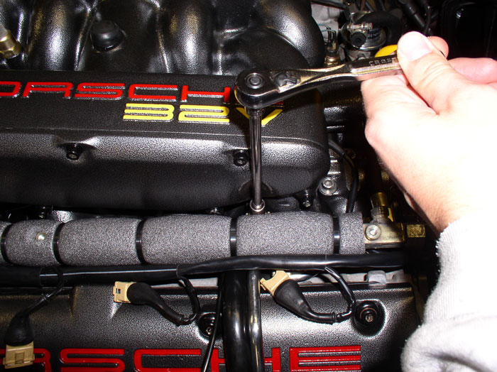
Next, use a 10mm socket wrench with extension to tighten the 2 fuel rail mounting nuts. Tighten to 7 ftlbs.
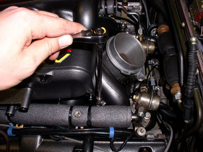
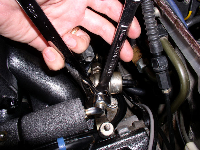
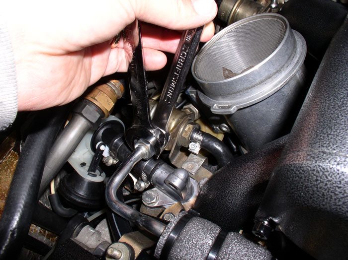
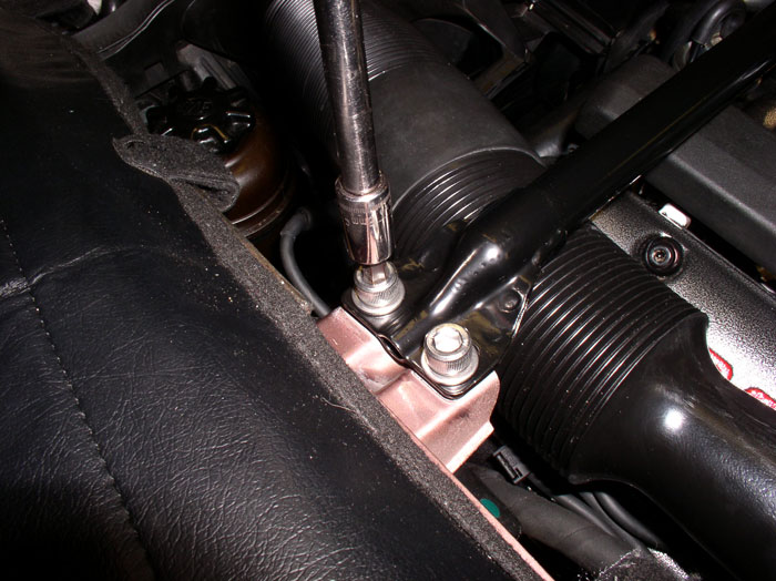
Thread the fuel rail rear connecting nut onto the rear FPD. Use a 19mm wrench to tighten the fuel rail nut and use a 15mm wrench to counterhold the FPD as shown. Snug firmly but don't overtighten as this can damage the sealing surfaces of the compression type fitting.
continued.....
Use a 22mm deep socket to re-install and snug down. I couldn't find a torque value in the manuals but given the ease with which the switch came out, 15 ftlbs seemed sufficient.
Next, route the harness connection to the temperature switch. Route the wire as shown below between the last two intake runner legs....
....and up behind the intake. Make sure enough wire is present to connect to the terminals. I did not connect mine to the switch just yet.
Now for the fuel injectors. If you sent your injectors off or removed them from the fuel rail, now's the time to install the injectors back into the fuel rail. I had my injectors temporarily installed into the intake to prevent debris from entering the head. If you did the same, remove them and install into the fuel rails. It's a good idea to use a lubricant on the upper and lower o-ring seals of the fuel injector. I've used a light coat of motor oil - you can also use another lubricant but ensure it is sensor-safe. Push the top of the fuel injector into the rail until it is fully seated. Orient the fuel injector so that the plug to the harness is facing away from the intake when the fuel rail is mounted (see below).
After the fuel injector is in, attach the retaining clip as shown. I oriented the retaining clip in the same manner as they were attached when I took them out.
Attach all four injectors to the fuel rail and then do the same for the other fuel rail.
Starting with the driver's side, position the fuel rail with injectors into place. Ensure the ends of the fuel rail line up with the fuel pressure dampers at each end. Also ensure the two mounting brackets on the fuel rail are lined up to fit over the M6 mounting studs on the intake. .
When you lower the fuel rail down into position, ensure the air temperature switch wires harness is routed between cylinders 6 and 7 fuel injectors as shown. Also, it is very important that you ensure each injector is lined up to go into is respective injector hole in the intake. Otherwise, a misaligned injector can result in a cracked pintle cap while pressing the fuel rail down into place.
Then press down on the fuel rail until all four injectors are fully seated. The fuel rail mounting brackets will only allow you to push down so far until the brackets are seated on their M6 studs.
Before installing and tightening down the 10mm nut on the fuel rail mounting brackets, ensure the end of the fuel rail is perfectly aligned with the Fuel Pressure Damper (FPD) receiving end (see green arrow). It is important that the fuel rail is not in a bind as a result of misalignment of the fuel rail connection at the FPDs - otherwise it may lead to leaking seals (vacuum leak) at the fuel injectors. Install the 10mm nut on the fuel rail mounting stud at the rear of the fuel rail.
To reach the mounting stud on the front of the fuel rail, I used a magnetic pick-up tool to hold the nut....
....then placed the nut on the stud and turned the magnetic tool until the nut was started on the threads.
Next, use a 10mm socket wrench with extension to tighten the 2 fuel rail mounting nuts. Tighten to 7 ftlbs.
Thread the fuel rail rear connecting nut onto the rear FPD. Use a 19mm wrench to tighten the fuel rail nut and use a 15mm wrench to counterhold the FPD as shown. Snug firmly but don't overtighten as this can damage the sealing surfaces of the compression type fitting.
continued.....
Last edited by Dwayne; 02-07-2009 at 10:17 AM.
02-08-2009, 12:00 PM
#145
Rennlist Member
Thread Starter
Join Date: Sep 2007
Location: Ridgecrest, California
Posts: 1,363
Likes: 0
Received 143 Likes
on
28 Posts
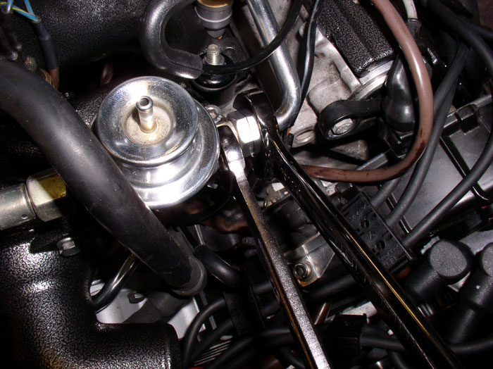
Now, thread the front fuel rail connecting nut to the front FPD. Ensure the fuel rail is perfectly aligned with the FPD and is not in a bind. If it does not line up, check the installation of the fuel rail to make sure nothing is causing the connection to misalign. You may need to slightly loosen the FPD from the water bridge to adjust the connection. Then, use a 19mm wrench to tighten down the 19mm nut while using a 15mm wrench to counterhold the FPD. Tighten in the same manner as the rear FPD.
Next, move over to the passenger side of the intake. I positioned the rear knock sensor connection so that it would be tucked between the fuel rail and the intake runners out of sight.
Position the fuel rail into place. Line up the fuel rail to rear FPR connection and ensure all fuel injectors are lined up with their respective holes in the intake. Also, make sure the fuel rail mounting tabs are lined up with the two M6 studs on the intake (same procedure as just completed on the driver's side). Then push down on the fuel rail until it is seated.
Install the 10mm nuts that secure the fuel rail to the intake and tighten with 10mm socket down to 7 ftlbs.
Ensure the rear FPR and fuel rail connection are perfectly aligned and thread the 19mm nut onto the FPR. Then tighten nut with a 19mm wrench and counterhold the FPR with a 15mm wrench. Tighten in the same manner as the driver's side connections.
Attach the front fuel hose to the front of the fuel rail and tighten down with a 19mm wrench. You can counterhold the fuel rail with another 19mm wrench.
Go ahead and attach the Temp II sensor plug onto the sensor.
Before connecting the fuel injectors to the wiring harness and installing the fuel rail covers, I found it best to perform a vacuum leak test at this stage before making final connections so that I didn't have as much re-work to take things off to repair the leaks. I learned this the hard way by connecting EVERYTHING back together and starting the car - hoping it would run perfectly. It didn't - I had leaks and had to take things apart again to fix them.
So first, connect the vacuum elbow to the front FPD.
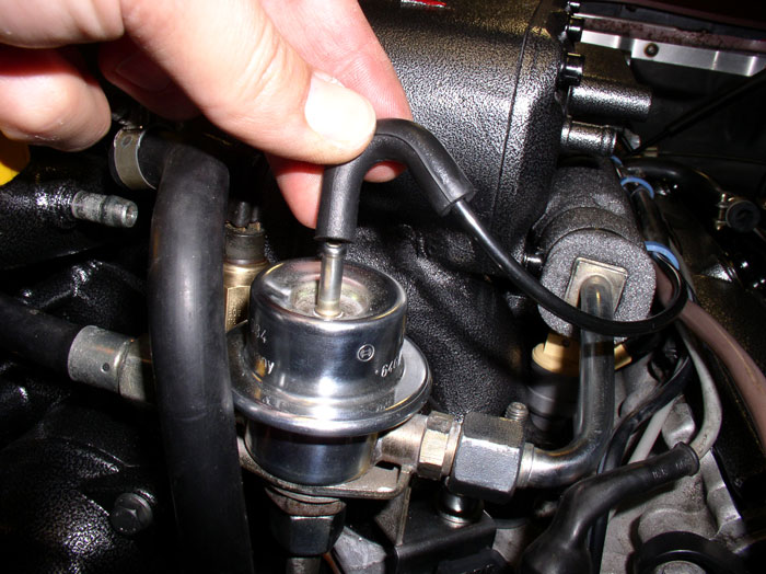
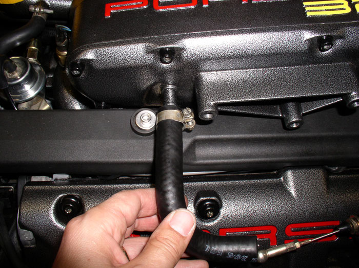
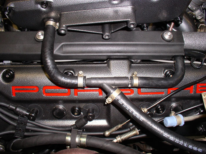
Then connect the 3-way hose to the oil filler neck and tighten down the hose clamp.
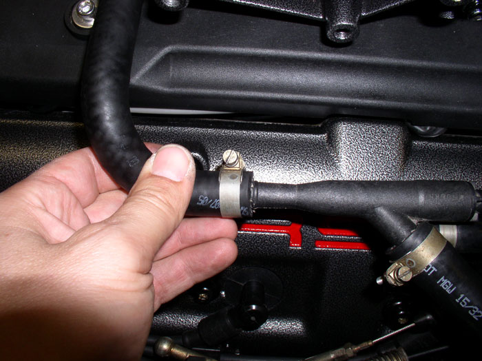
Next, connect the plenum-to-venturi hose to the port on the side cover of the plenum. Don't tighten the hose clamp yet. Ignore the fuel rail cover already in place - unfortunately, I did not have a picture of this without the fuel rail cover in place.
If you replaced all your hoses at the venturi like I did, connect the venturi-to-brake booster hose at the venturi next and tighten the hose clamp.
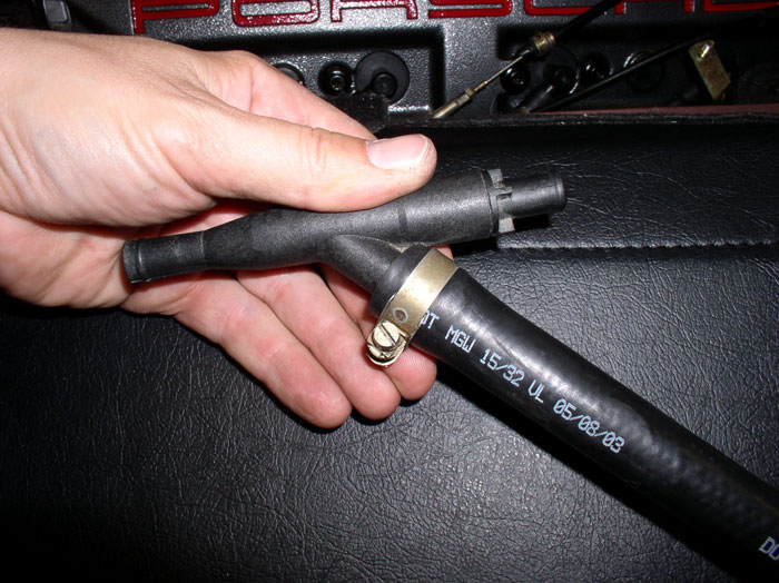
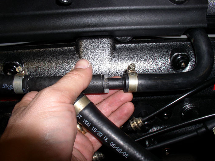
Then, connect the venturi assembly to the plenum hose you just attached to the plenum. Don't tighten the hose clamp yet.
Connect the hose coming from the Air Guide Cowl to the venturi assembly.
Connect the brake booster hose to the brake booster port. Tighten the hose clamp.
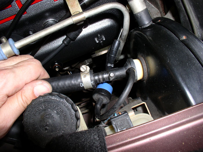
The hose connections should look like this (minus the fuel rail cover - sorry). With the hose assembly in place, go ahead and tighten all the hose clamps.
continued.....
Next, move over to the passenger side of the intake. I positioned the rear knock sensor connection so that it would be tucked between the fuel rail and the intake runners out of sight.
Position the fuel rail into place. Line up the fuel rail to rear FPR connection and ensure all fuel injectors are lined up with their respective holes in the intake. Also, make sure the fuel rail mounting tabs are lined up with the two M6 studs on the intake (same procedure as just completed on the driver's side). Then push down on the fuel rail until it is seated.
Install the 10mm nuts that secure the fuel rail to the intake and tighten with 10mm socket down to 7 ftlbs.
Ensure the rear FPR and fuel rail connection are perfectly aligned and thread the 19mm nut onto the FPR. Then tighten nut with a 19mm wrench and counterhold the FPR with a 15mm wrench. Tighten in the same manner as the driver's side connections.
Attach the front fuel hose to the front of the fuel rail and tighten down with a 19mm wrench. You can counterhold the fuel rail with another 19mm wrench.
Go ahead and attach the Temp II sensor plug onto the sensor.
Before connecting the fuel injectors to the wiring harness and installing the fuel rail covers, I found it best to perform a vacuum leak test at this stage before making final connections so that I didn't have as much re-work to take things off to repair the leaks. I learned this the hard way by connecting EVERYTHING back together and starting the car - hoping it would run perfectly. It didn't - I had leaks and had to take things apart again to fix them.
So first, connect the vacuum elbow to the front FPD.
Then connect the 3-way hose to the oil filler neck and tighten down the hose clamp.
Next, connect the plenum-to-venturi hose to the port on the side cover of the plenum. Don't tighten the hose clamp yet. Ignore the fuel rail cover already in place - unfortunately, I did not have a picture of this without the fuel rail cover in place.
If you replaced all your hoses at the venturi like I did, connect the venturi-to-brake booster hose at the venturi next and tighten the hose clamp.
Then, connect the venturi assembly to the plenum hose you just attached to the plenum. Don't tighten the hose clamp yet.
Connect the hose coming from the Air Guide Cowl to the venturi assembly.
Connect the brake booster hose to the brake booster port. Tighten the hose clamp.
The hose connections should look like this (minus the fuel rail cover - sorry). With the hose assembly in place, go ahead and tighten all the hose clamps.
continued.....
02-08-2009, 01:04 PM
#146
Rennlist Member
Thread Starter
Join Date: Sep 2007
Location: Ridgecrest, California
Posts: 1,363
Likes: 0
Received 143 Likes
on
28 Posts
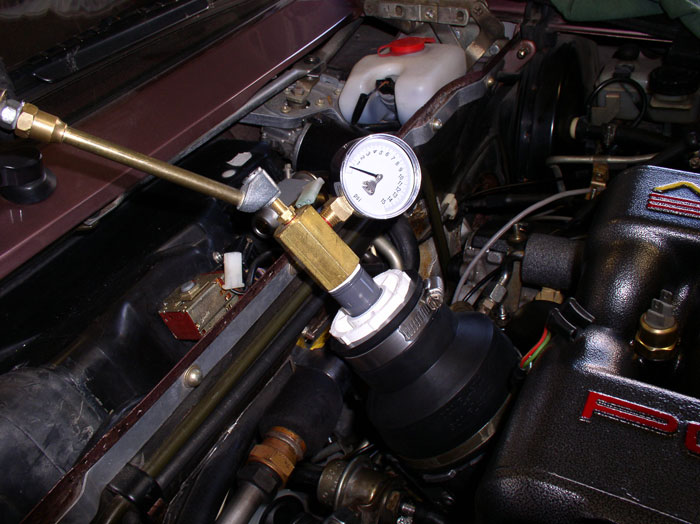
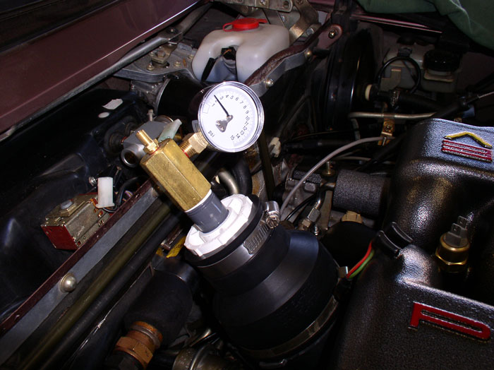
This is a great point to do a vacuum leak test before completing the rest of the intake installation. You may remember earlier in this thread that I described how to build the vacuum leak testing device. I use it here to test for leaks. After you've clamped the rubber adapter to the MAF, install the unit by inserting the MAF end into the Air Guid Cowl and tightenting the clamp nice and snug.
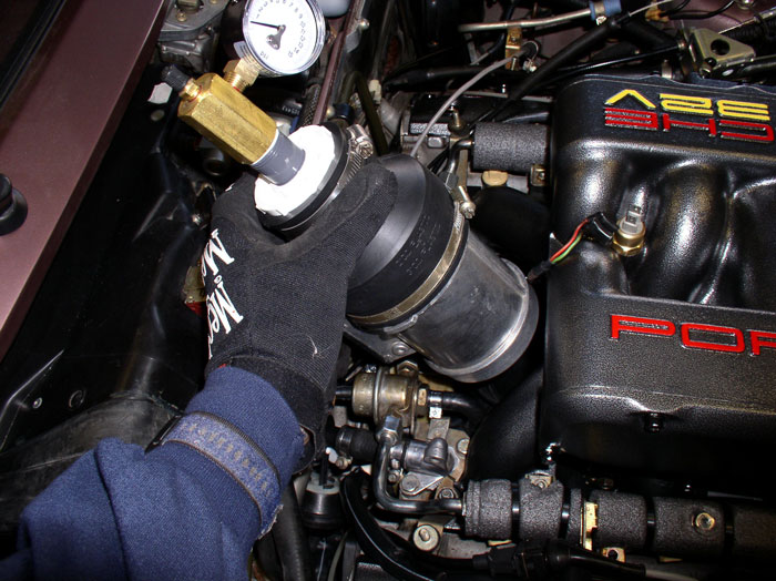
I pressurized the system to about 1-2 PSI and watch the pressure gauge to see how quickly it falls.
If you have a leak, it will be obvious by the steady drop in pressure on the gauge. If it's a large leak, you will be able to hear it. Next you will need to pinpoint the leak. I used a spray bottle filled with a very small amount of dishwashing soap and water and sprayed at locations where the sound was coming from. At places I couldn't get the spray (e.g., throttle body linkage), I used a long wooden match and could see the air nearly blowing out the match near the leak. The leaks I had were the following: A huge leak was caused by a misaligned cam cover gasket on the passenger side. After fixing that and pressurizing again, I found I had a large leak at the fuel injectors lower O-ring caused by the fuel rail being in a bind because the fuel rail was not perfectly aligned with the FPDs on the driver's side (hence, my comments about alignment of the fuel rail and FPD/FPR). After repairing these and pressurizing again, I found I had a large leak at the throttle body linkage using the long wooden match to pinpoint. After removing the intake again and repairing the throttle body leak with Roger's flappy bearings - I pressurized again and achieved a very good seal (IMHO). After these repairs, I was able to pressurize to 2.5 PSI and monitored the drop. It took about 4 minutes to drop to zero. Which seemed good enough to me.
Once your happy with the sealing qualities of the intake system, you can remove the testing device and finish the fuel rail assembly. First, I connected the fuel injector harness plugs to the fuel injectors. If you collected the retaining clip for the plugs, now's the time to install the clips back into the plugs. When I originally removed my injector plugs from the injectors, about half of the injector clips simply fell off. None of the clips were secured to the plug housing. I removed all of them from the plugs as they would easily come off and fall into the engine during the intake repair. The following procedure illustrates how I put them back in. However, thanks to some valuable insight from Bill Ball (THANKS, Bill!), there are other, highly recommended ways to secure the clips to the plugs more permanently. First, you can buy the clips that have the 90 degree bend at the ends that secure the clip to the plug. I understand these may be available still if you buy the pigtail plug kit and simply remove the clip from the new pigtail and use it on your existing plug. Another way is to simply using a soldering iron to melt some of the surrounding plastic on the front side of the plug over the wire clip to hold it in place. Unfortunately, I did not know about either of these alternatives at the time of this repair so I would strongly recommend the more permanant solution when you re-install the fuel injector plugs. I'm going to try to order some of the 90 degree clips as soon as possible and re-install the plugs. THANKS again, Bill for this valuable tip!
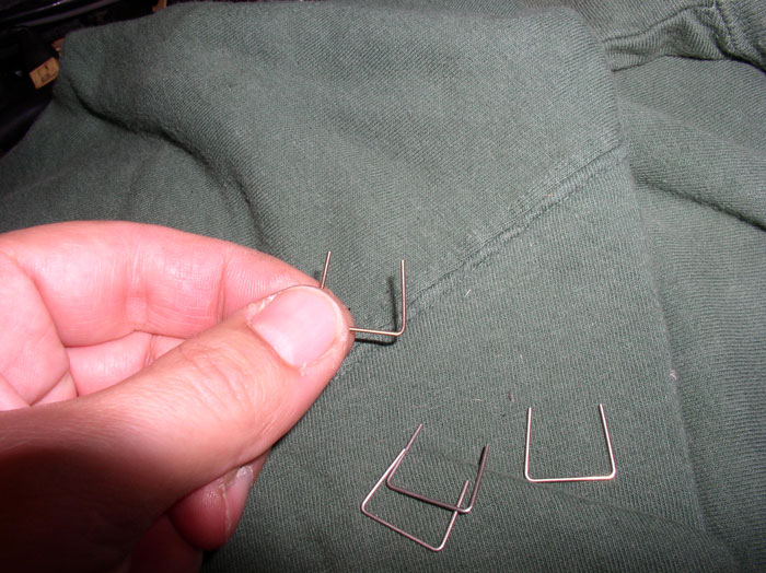
It can be a little tricky to get the clips back into the plugs but here's the procedure I used. Begin by inserting the clip about 3/4 the way into its slot in the plug as shown.
Then, use a pair of circlip pliers to pry the clip open enough to press the clip in all the way until it's fully seated. I found it handy to simply position the pliers into the recessed openings in the plug and apply pressure to the pliers until they were fully seated against the walls of the plug - then press the clip into place with your finger (see below).
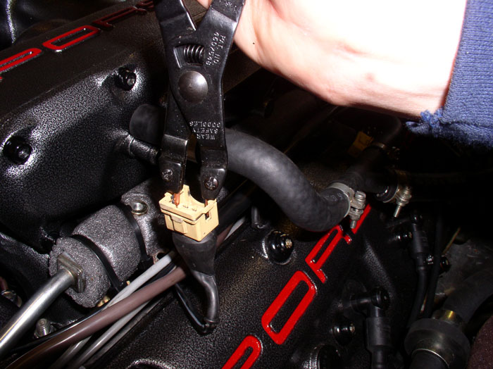
Next, install the fuel injector plug onto the associated fuel injector until you feel/hear it click into place.
With these clips, I noticed that after it "clicked" into place, the clip would "back out" from the plug about 1/8 inch. Therefore, use a screwdriver as shown to simply push the clip back into its fully seated position. I had to do this on all eight injectors. Next time, I'll locate some of the clips with the 90 degree locking bend on the ends (as Bill Ball suggests) and install those.
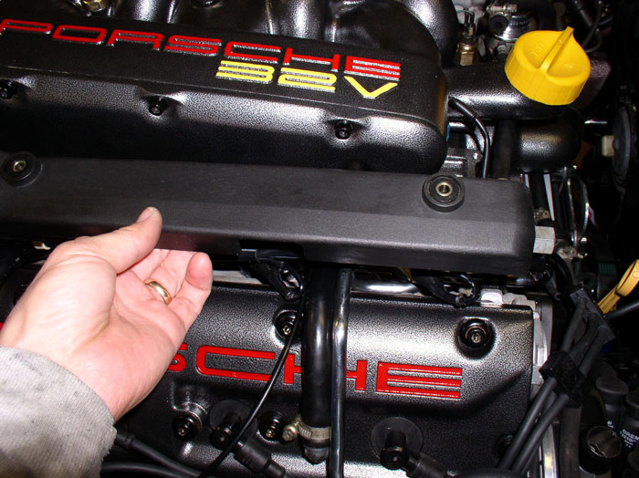
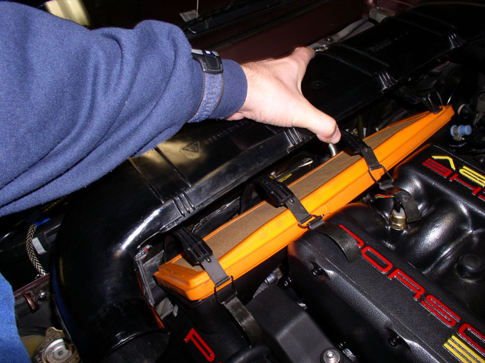
Next, install the fuel rail covers. I started with the driver's side. You can remove the plenum-to-venturi hose from the side cover plate of the plenum to make room for installation. Slide the fuel rail in from the front as shown.
Line up the mounting holes of the cover with the mounts on the rail and install the M6 bolts using a 5mm allen head socket. My previous bolts were too corroded and small to clean appropriately so I replaced them with the same sized stainless steel equivalent. These do not require a lot of torque, I just simply "snugged" them down.
While you're on the driver's side, you can connect the intake air temp sensor wires to the sensor as shown. It does not matter which post the wires are connected to.
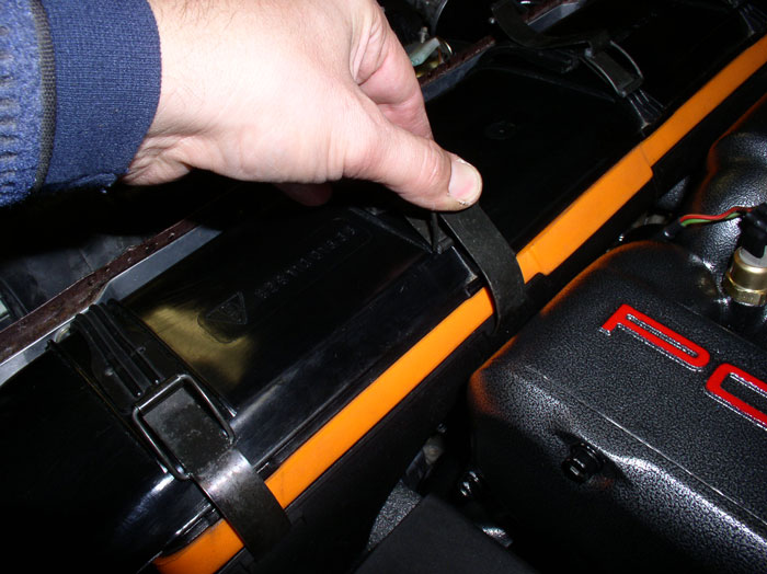
Next, comes the passenger side fuel rail cover. Simply position this cover over the rail from above and line up the mounting holes with the fuel rail....
....and snug down the two 5mm allen head bolts.
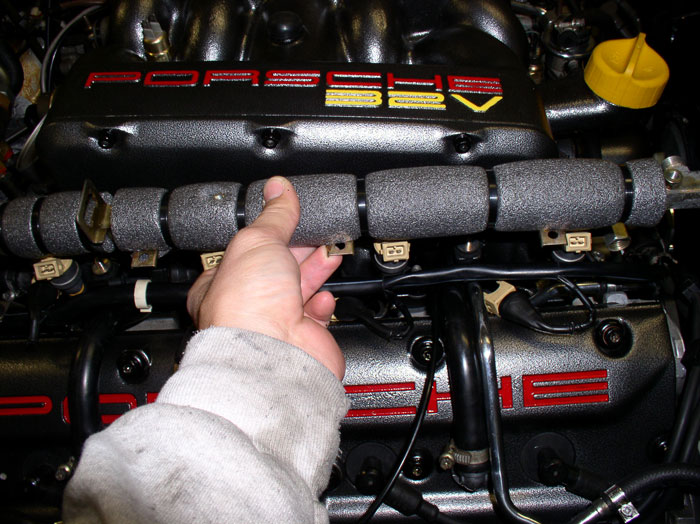
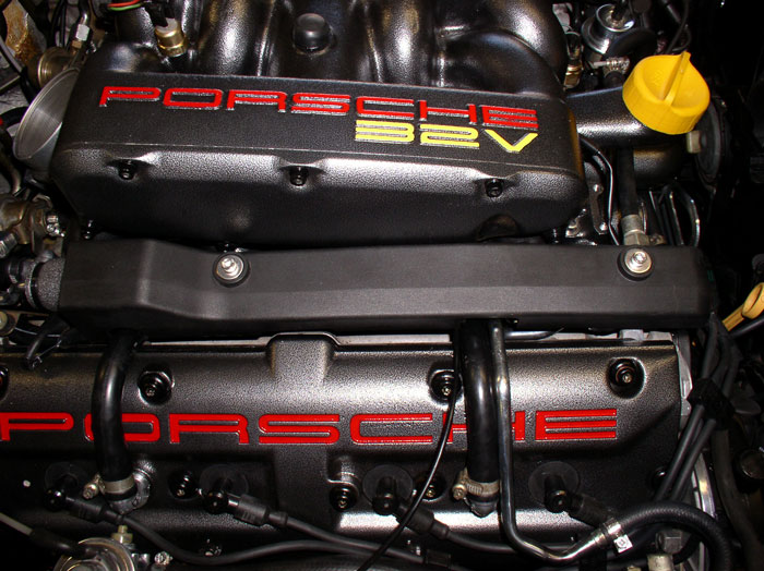
When done, it should look something like this.
continued.....
I pressurized the system to about 1-2 PSI and watch the pressure gauge to see how quickly it falls.
If you have a leak, it will be obvious by the steady drop in pressure on the gauge. If it's a large leak, you will be able to hear it. Next you will need to pinpoint the leak. I used a spray bottle filled with a very small amount of dishwashing soap and water and sprayed at locations where the sound was coming from. At places I couldn't get the spray (e.g., throttle body linkage), I used a long wooden match and could see the air nearly blowing out the match near the leak. The leaks I had were the following: A huge leak was caused by a misaligned cam cover gasket on the passenger side. After fixing that and pressurizing again, I found I had a large leak at the fuel injectors lower O-ring caused by the fuel rail being in a bind because the fuel rail was not perfectly aligned with the FPDs on the driver's side (hence, my comments about alignment of the fuel rail and FPD/FPR). After repairing these and pressurizing again, I found I had a large leak at the throttle body linkage using the long wooden match to pinpoint. After removing the intake again and repairing the throttle body leak with Roger's flappy bearings - I pressurized again and achieved a very good seal (IMHO). After these repairs, I was able to pressurize to 2.5 PSI and monitored the drop. It took about 4 minutes to drop to zero. Which seemed good enough to me.
Once your happy with the sealing qualities of the intake system, you can remove the testing device and finish the fuel rail assembly. First, I connected the fuel injector harness plugs to the fuel injectors. If you collected the retaining clip for the plugs, now's the time to install the clips back into the plugs. When I originally removed my injector plugs from the injectors, about half of the injector clips simply fell off. None of the clips were secured to the plug housing. I removed all of them from the plugs as they would easily come off and fall into the engine during the intake repair. The following procedure illustrates how I put them back in. However, thanks to some valuable insight from Bill Ball (THANKS, Bill!), there are other, highly recommended ways to secure the clips to the plugs more permanently. First, you can buy the clips that have the 90 degree bend at the ends that secure the clip to the plug. I understand these may be available still if you buy the pigtail plug kit and simply remove the clip from the new pigtail and use it on your existing plug. Another way is to simply using a soldering iron to melt some of the surrounding plastic on the front side of the plug over the wire clip to hold it in place. Unfortunately, I did not know about either of these alternatives at the time of this repair so I would strongly recommend the more permanant solution when you re-install the fuel injector plugs. I'm going to try to order some of the 90 degree clips as soon as possible and re-install the plugs. THANKS again, Bill for this valuable tip!
It can be a little tricky to get the clips back into the plugs but here's the procedure I used. Begin by inserting the clip about 3/4 the way into its slot in the plug as shown.
Then, use a pair of circlip pliers to pry the clip open enough to press the clip in all the way until it's fully seated. I found it handy to simply position the pliers into the recessed openings in the plug and apply pressure to the pliers until they were fully seated against the walls of the plug - then press the clip into place with your finger (see below).
Next, install the fuel injector plug onto the associated fuel injector until you feel/hear it click into place.
With these clips, I noticed that after it "clicked" into place, the clip would "back out" from the plug about 1/8 inch. Therefore, use a screwdriver as shown to simply push the clip back into its fully seated position. I had to do this on all eight injectors. Next time, I'll locate some of the clips with the 90 degree locking bend on the ends (as Bill Ball suggests) and install those.
Next, install the fuel rail covers. I started with the driver's side. You can remove the plenum-to-venturi hose from the side cover plate of the plenum to make room for installation. Slide the fuel rail in from the front as shown.
Line up the mounting holes of the cover with the mounts on the rail and install the M6 bolts using a 5mm allen head socket. My previous bolts were too corroded and small to clean appropriately so I replaced them with the same sized stainless steel equivalent. These do not require a lot of torque, I just simply "snugged" them down.
While you're on the driver's side, you can connect the intake air temp sensor wires to the sensor as shown. It does not matter which post the wires are connected to.
Next, comes the passenger side fuel rail cover. Simply position this cover over the rail from above and line up the mounting holes with the fuel rail....
....and snug down the two 5mm allen head bolts.
When done, it should look something like this.
continued.....
Last edited by Dwayne; 02-08-2009 at 05:25 PM.
02-08-2009, 02:35 PM
#147
Rennlist Member
Thread Starter
Join Date: Sep 2007
Location: Ridgecrest, California
Posts: 1,363
Likes: 0
Received 143 Likes
on
28 Posts
Coming down the home stretch now. Re-connect the plenum-to-venturi hose to the side cover plate of the plenum and tighten the clamp.
Attach the cable linkage bracket to the mounting holes on the side of the plenum. Attach with three 13mm bolts as shown. Torque to 15 ftlbs.
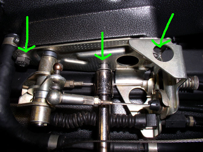
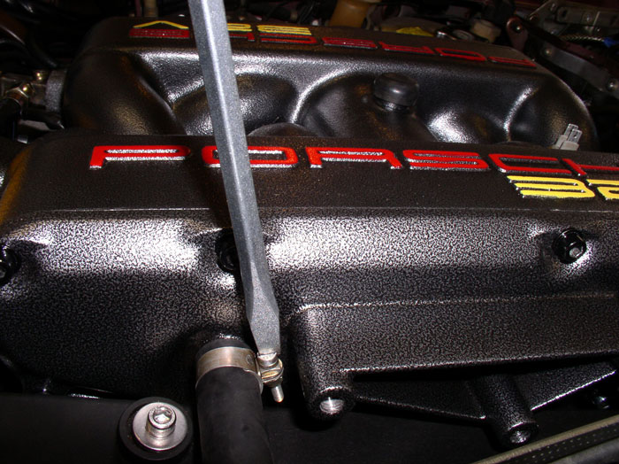
I put black grease on the acclerator cable ball connector at the lever arm as shown.
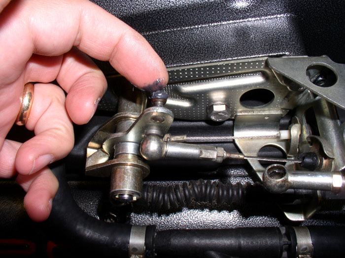
Thread the accelerator cable through the square hole in the cable linkage bracket and push the plastic connector in until it "clicks" into place. Pull on the end of the accelerator cable to make sure it is operating smoothly and the cable has not come off the cable wheel near the throttle body. If it works smoothly, attach the ball connector at the end of the cable to the ball at the lever arm and press into place until it "snaps" on.
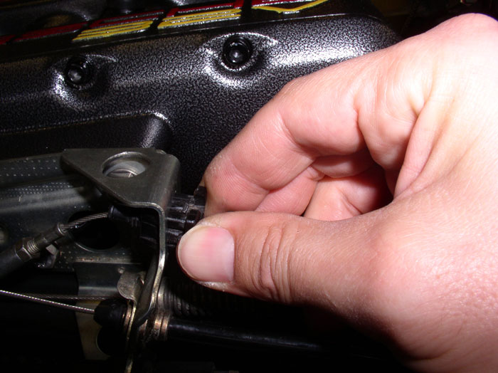
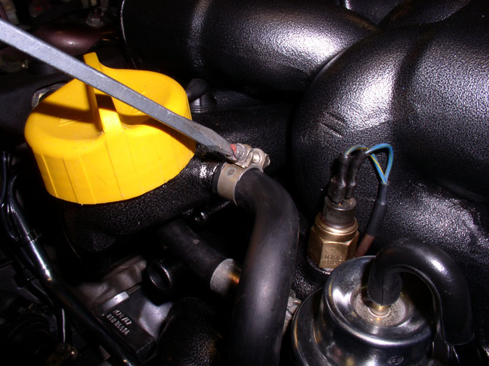
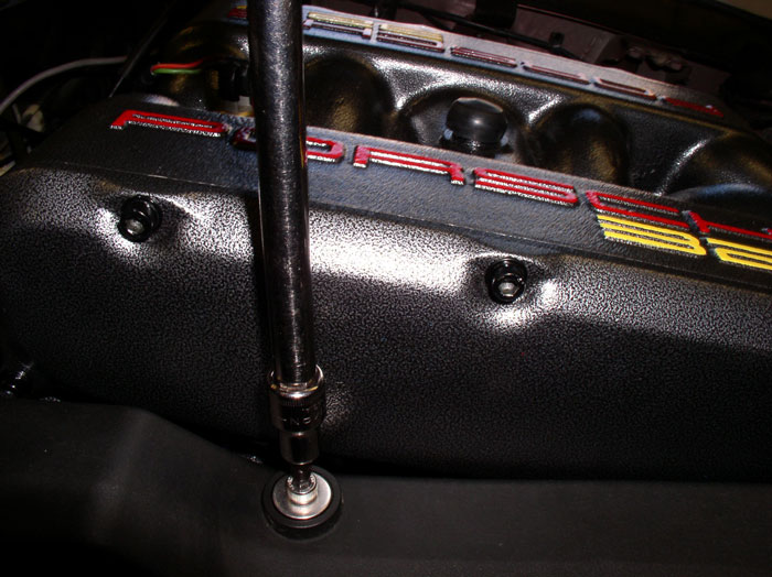
Work the cable linkage with your hand to see if the TPS idle contact switch is working correctly. When you open the throttle plate (rotating cable linkage clockwise as if accelerating) and release slowly, you should hear the click of the idle contact of the TPS. It should click when you slightly move the cable linkage off idle position and it should click again when you release the linkage slowly. If the cable linkage will not return to idle position on its own, you may need to adjust the accelerator cable tension. I had to make a minor adjustment to mine to get it operate perfectly. Accelerator cable tension can be adjusted by the threaded cable connection at the firewall as shown. Increasing the number of threads visible (turning counter-clockwise) increases the tension accordingly. Reducing the number of threads visible (turning clockwise) creates more slack.
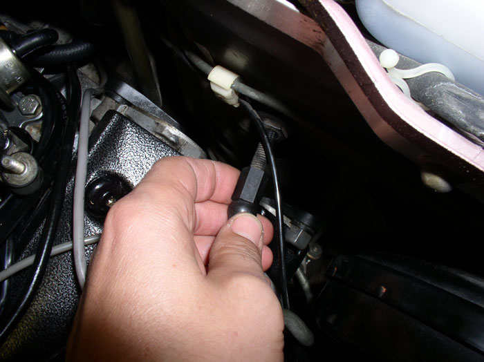
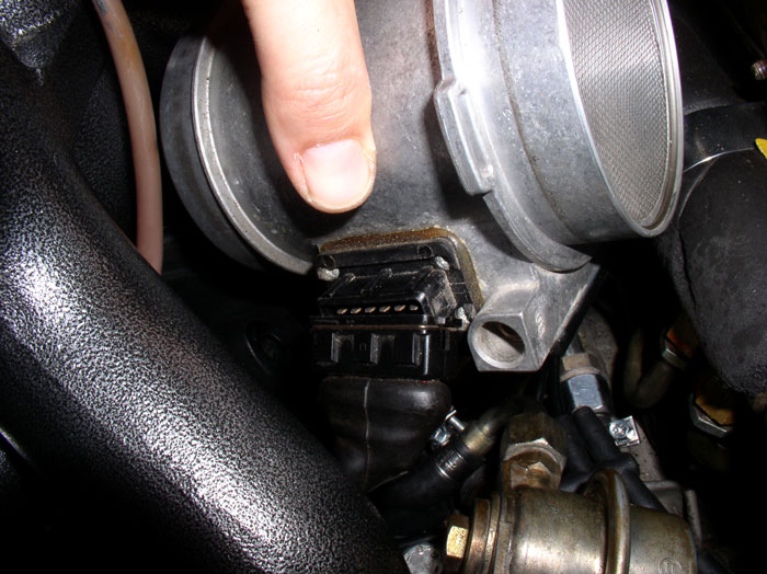
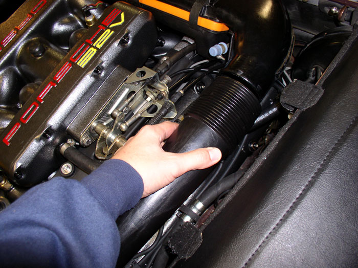
Next, install the Mass Air Flow (MAF) sensor. After you've removed it from the vacuum testing device, position it near the cowl and connect the harness plug. Then, fit the MAF into the Air Guide Cowl making sure it is fully seated. Tighten the clamp on the cowl.
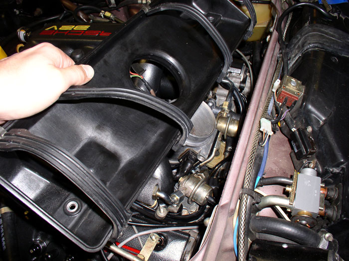
Install the lower half of the air filter box. Position it into place over the MAF and press the MAF sealing ring onto the MAF. At the same time, ensure the mounting studs (two on each end of the box) are lined up with their respective holes in the box.
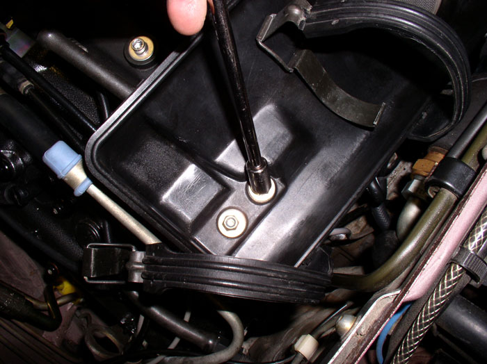
Tighten down the air box using the 10mm nuts and washers as shown.
Next, install the air diverter valve hose that connects to the top half of the air filter box. You can install the hose, leave the clamp loose and dry fit the top of the filter box in place to line up the hose with its port on the air box lid. Then remove the lid and tighten the hose clamp at the diverter valve.
Install the air filter. You will notice arrows imprinted on the end of the air filter. Make sure these arrows are pointed upwards. Then install the top of the air filter box, lining up the air diverter valve hose with the port underneath the lid.
Secure the air box lid clamps and tighten the air diverter valve hose clamp underneath.
Install the air tubes next.
Then, re-install the belly pans in the order they were removed and lower the car. Install the cross brace next. Tighten the 8mm allen head bolts to 30 ftlbs. Then, after the suspension settles, I came back and loosened them and watched the fenders move in slightly and re-tightened the bolts back down.
continued......
Attach the cable linkage bracket to the mounting holes on the side of the plenum. Attach with three 13mm bolts as shown. Torque to 15 ftlbs.
I put black grease on the acclerator cable ball connector at the lever arm as shown.
Thread the accelerator cable through the square hole in the cable linkage bracket and push the plastic connector in until it "clicks" into place. Pull on the end of the accelerator cable to make sure it is operating smoothly and the cable has not come off the cable wheel near the throttle body. If it works smoothly, attach the ball connector at the end of the cable to the ball at the lever arm and press into place until it "snaps" on.
Work the cable linkage with your hand to see if the TPS idle contact switch is working correctly. When you open the throttle plate (rotating cable linkage clockwise as if accelerating) and release slowly, you should hear the click of the idle contact of the TPS. It should click when you slightly move the cable linkage off idle position and it should click again when you release the linkage slowly. If the cable linkage will not return to idle position on its own, you may need to adjust the accelerator cable tension. I had to make a minor adjustment to mine to get it operate perfectly. Accelerator cable tension can be adjusted by the threaded cable connection at the firewall as shown. Increasing the number of threads visible (turning counter-clockwise) increases the tension accordingly. Reducing the number of threads visible (turning clockwise) creates more slack.
Next, install the Mass Air Flow (MAF) sensor. After you've removed it from the vacuum testing device, position it near the cowl and connect the harness plug. Then, fit the MAF into the Air Guide Cowl making sure it is fully seated. Tighten the clamp on the cowl.
Install the lower half of the air filter box. Position it into place over the MAF and press the MAF sealing ring onto the MAF. At the same time, ensure the mounting studs (two on each end of the box) are lined up with their respective holes in the box.
Tighten down the air box using the 10mm nuts and washers as shown.
Next, install the air diverter valve hose that connects to the top half of the air filter box. You can install the hose, leave the clamp loose and dry fit the top of the filter box in place to line up the hose with its port on the air box lid. Then remove the lid and tighten the hose clamp at the diverter valve.
Install the air filter. You will notice arrows imprinted on the end of the air filter. Make sure these arrows are pointed upwards. Then install the top of the air filter box, lining up the air diverter valve hose with the port underneath the lid.
Secure the air box lid clamps and tighten the air diverter valve hose clamp underneath.
Install the air tubes next.
Then, re-install the belly pans in the order they were removed and lower the car. Install the cross brace next. Tighten the 8mm allen head bolts to 30 ftlbs. Then, after the suspension settles, I came back and loosened them and watched the fenders move in slightly and re-tightened the bolts back down.
continued......
02-08-2009, 03:40 PM
#148
Under the Lift
Lifetime Rennlist
Member
Lifetime Rennlist
Member
Dwayne:
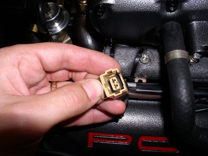
Sorry to interrupt your workflow again. You noted that those wire clips on the injector electrical plug are a problem. As you have them now, they can easily fall off and allow the plug to come free and the injector to stop firing. If you don't install the updated style wires, then you should try to re-fix the clips to the injector plug. They were originally held inplace by a bit of plastic melted over the channel at the base of the clip (see illustration below). That plastic can chip off and lead to what you have. I've successfuly used a soldering iron to work some of the adjacent plastic over the wire in the channel, recreating the original. Wish I had taken some pictures! I thought about just putting a dab of epoxy over the wire there. I thought it probably wouldn't hold, but that might be another alternative. The wires are only supposed to be able to spring at the sides and otherwise should be anchored to the plug so they won't fall off.
I'm repeating myself, but you can get the newer styler wire clips that cannot fall off by buying new pigtails (all over eBay for a little over $2 each - er, they used to be. I see they are getting harder to find. They are obsolete.) and just moving the new style wire clip over to your current plugs. No need to replace the entire pigtail. You can save the rest of the pigtail until needed later.
02-08-2009, 04:52 PM
#149
Addict
Rennlist Member
Rennlist Member
Join Date: Oct 2003
Location: Gone. On the Open Road
Posts: 16,321
Received 1,542 Likes
on
1,006 Posts
02-08-2009, 05:27 PM
#150
Rennlist Member
Thread Starter
Join Date: Sep 2007
Location: Ridgecrest, California
Posts: 1,363
Likes: 0
Received 143 Likes
on
28 Posts
Dwayne:
Sorry to interrupt your workflow again. You noted that those wire clips on the injector electrical plug are a problem. As you have them now, they can easily fall off and allow the plug to come free and the injector to stop firing. If you don't install the updated style wires, then you should try to re-fix the clips to the injector plug. They were originally held inplace by a bit of plastic melted over the channel at the base of the clip (see illustration below). That plastic can chip off and lead to what you have. I've successfuly used a soldering iron to work some of the adjacent plastic over the wire in the channel, recreating the original. Wish I had taken some pictures! I thought about just putting a dab of epoxy over the wire there. I thought it probably wouldn't hold, but that might be another alternative. The wires are only supposed to be able to spring at the sides and otherwise should be anchored to the plug so they won't fall off.
I'm repeating myself, but you can get the newer styler wire clips that cannot fall off by buying new pigtails (all over eBay for a little over $2 each - er, they used to be. I see they are getting harder to find. They are obsolete.) and just moving the new style wire clip over to your current plugs. No need to replace the entire pigtail. You can save the rest of the pigtail until needed later.
I've updated the original post with your sound advice. THANKS again!
Now, back to our regularly scheduled program.....

