
'87 Intake Removal, Repairs, Installation Procedure (w/pics)
 01-29-2009, 01:02 AM
#121
Rennlist Member
Thread Starter
Join Date: Sep 2007
Location: Ridgecrest, California
Posts: 1,363
Likes: 0
Received 143 Likes
on
28 Posts
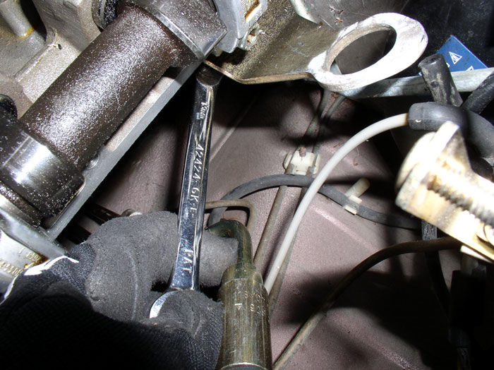
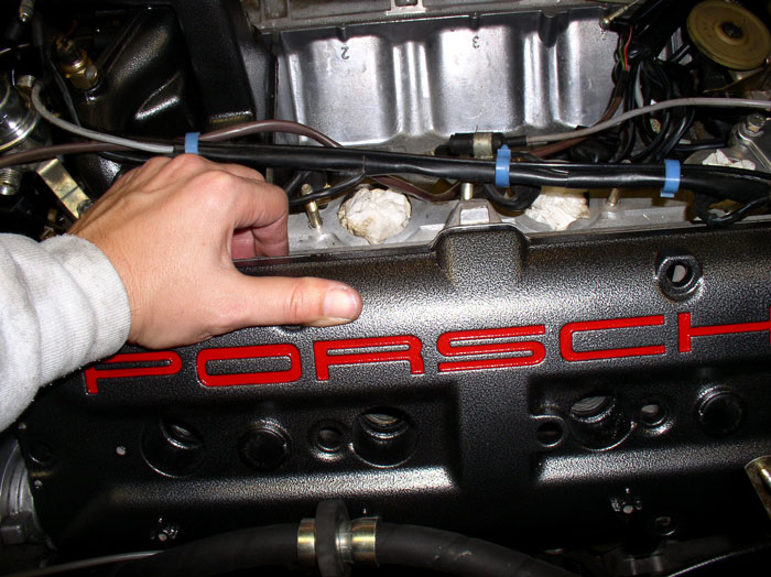
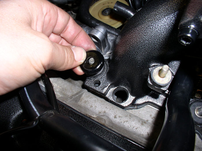
Now for the driver's side cam covers. To ease installation, I removed the engine lift hook. As I recall, the engine lift hook did not pose a problem on removal of the cam cover but I could use the extra space on installation. The bracket is held on to the head by a single 13mm bolt. Remove the bolt. You can access this one from above the engine.
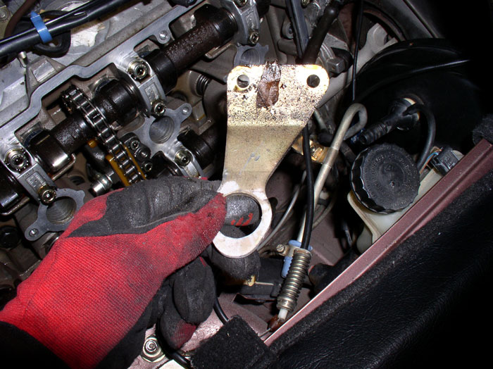
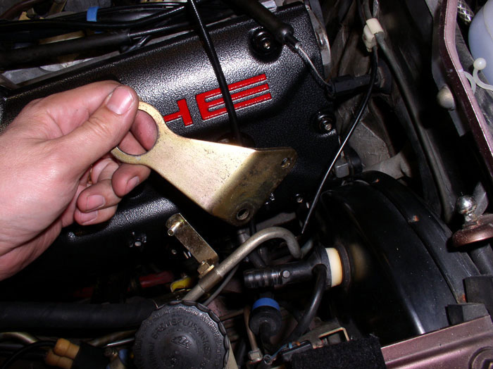
After the bolt is removed, take out the bracket. It has two mounting holes but one of the holes is for a locator pin protruding from the side of the head.
Prepare the cam cover in the same manner as the passenger side described previously using the sensor safe gasket sealer/adheasive to secure the gaskets before installation.
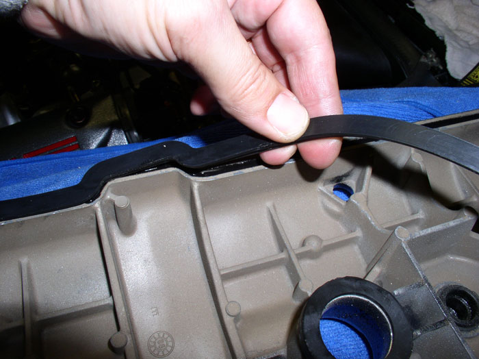
Don't forget to dab the 4 corners of the head with the gasket sealer/adheasive.
Next, maneuver the cam cover into place.
Then start placing the cam cover bolts. Like the passenger side, I started torquing the middle row first, then the top row then the bottom row using the 5mm allen socket. In order to get enough room to access the front lower bolt, I removed the driver's side coil. I could then get the torque wrench in to tighten the bolt down. I was also able to use the torque wrench to get at the last bolt and 2nd to the last bolt(toward rear of engine) on the bottom row of the cam cover.
The other bolt on the bottom row I had to use the 5mm allen key wrench and guess at the torque value. It also required holding the power steering hose out of the way with one hand while tightening with the other.
Next, re-install the driver's side engine lift hook. Locate the lift hook on the locator pin protruding from the side of the head first then install the 13mm bolt and tighten down.
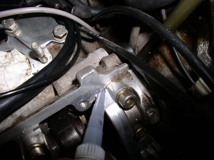
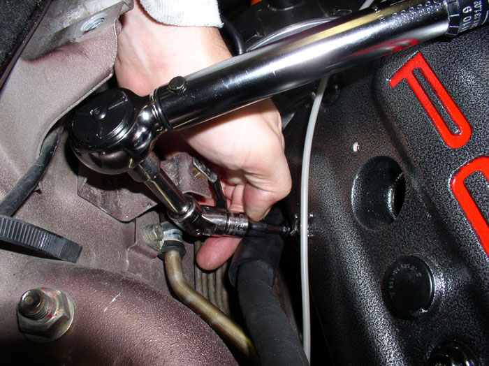
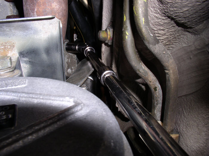
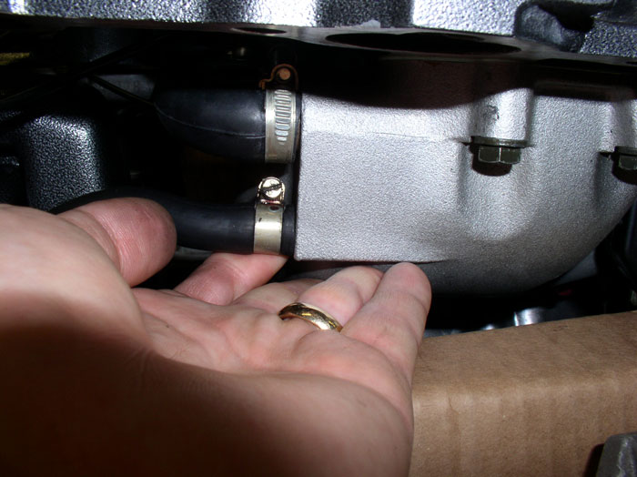
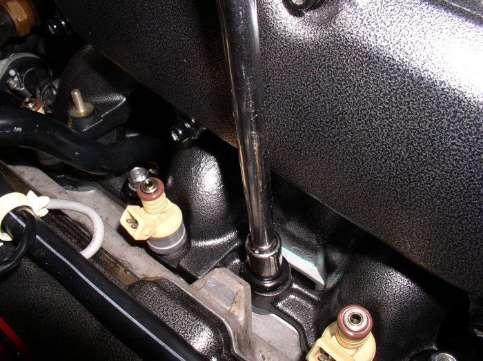
On the passenger side, re-install the engine lift hook as well. Same process as on the driver's side but you will need to tighten the 13mm bolt from underneath the car using extensions and a universal elbow as shown. I worked above to get the bolt started with my fingers then went underneath to tighten.
Once the lift bracket is installed, re-attach the wiring harness clamp to the engine lift bracket. The ground lead should be underneath the harness clamp. Tighten the 10mm bolt.
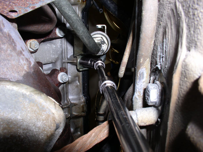
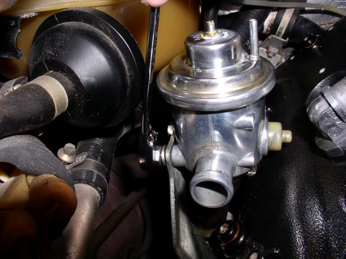
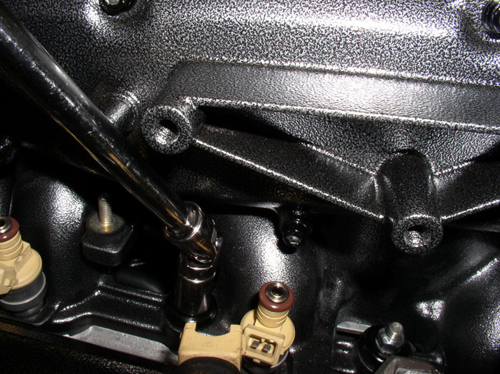
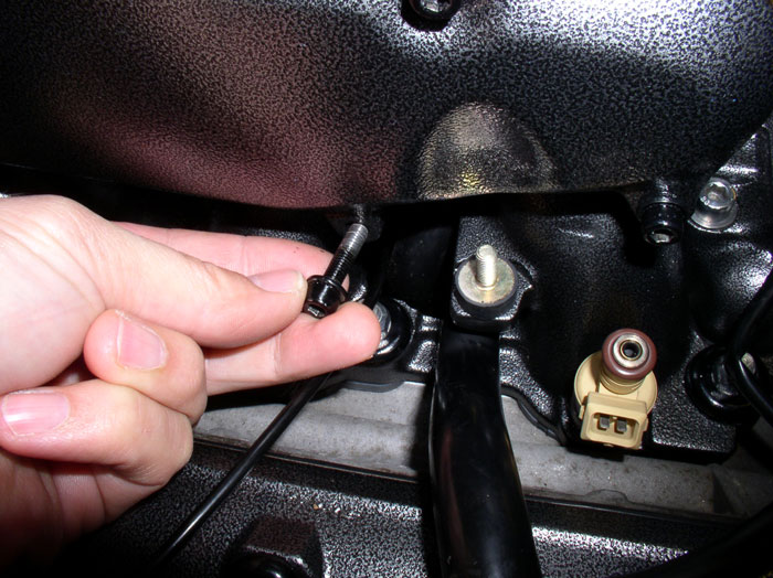
Next, install the bolts that secure the air diverter bracket to the cylinder head on the passenger side. You may be able to reach the bolts by hand from underneath to get them started. Otherwise, you can place the bolt in the socket and use the extensions to get the bolts started. Then tighten them both down.
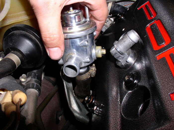
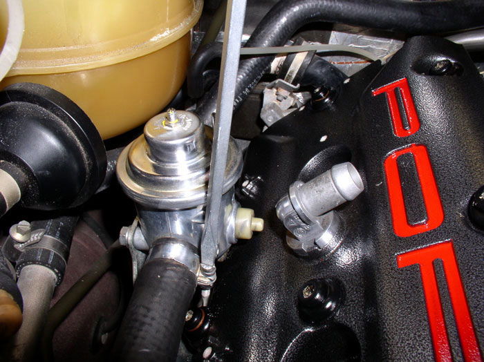
Install the diverter valve onto the rubber hose beneath the valve. The rubber hose connects to a metal pipe that runs into the catalytic converter. Orient the valve as shown. Don't tighten the hose clamp yet.
Next, install the two 10mm bolts that secure the diverter valve to the bracket.
Then tighten the hose clamp on the bottom of the diverter valve.
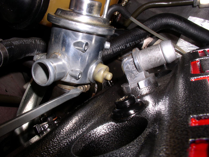
Finally, attach the inlet hose to the diverter valve and tighten the hose clamp.
Now you're ready for the final phase - installing the intake.
continued.....
After the bolt is removed, take out the bracket. It has two mounting holes but one of the holes is for a locator pin protruding from the side of the head.
Prepare the cam cover in the same manner as the passenger side described previously using the sensor safe gasket sealer/adheasive to secure the gaskets before installation.
Don't forget to dab the 4 corners of the head with the gasket sealer/adheasive.
Next, maneuver the cam cover into place.
Then start placing the cam cover bolts. Like the passenger side, I started torquing the middle row first, then the top row then the bottom row using the 5mm allen socket. In order to get enough room to access the front lower bolt, I removed the driver's side coil. I could then get the torque wrench in to tighten the bolt down. I was also able to use the torque wrench to get at the last bolt and 2nd to the last bolt(toward rear of engine) on the bottom row of the cam cover.
The other bolt on the bottom row I had to use the 5mm allen key wrench and guess at the torque value. It also required holding the power steering hose out of the way with one hand while tightening with the other.
Next, re-install the driver's side engine lift hook. Locate the lift hook on the locator pin protruding from the side of the head first then install the 13mm bolt and tighten down.
On the passenger side, re-install the engine lift hook as well. Same process as on the driver's side but you will need to tighten the 13mm bolt from underneath the car using extensions and a universal elbow as shown. I worked above to get the bolt started with my fingers then went underneath to tighten.
Once the lift bracket is installed, re-attach the wiring harness clamp to the engine lift bracket. The ground lead should be underneath the harness clamp. Tighten the 10mm bolt.
Next, install the bolts that secure the air diverter bracket to the cylinder head on the passenger side. You may be able to reach the bolts by hand from underneath to get them started. Otherwise, you can place the bolt in the socket and use the extensions to get the bolts started. Then tighten them both down.
Install the diverter valve onto the rubber hose beneath the valve. The rubber hose connects to a metal pipe that runs into the catalytic converter. Orient the valve as shown. Don't tighten the hose clamp yet.
Next, install the two 10mm bolts that secure the diverter valve to the bracket.
Then tighten the hose clamp on the bottom of the diverter valve.
Finally, attach the inlet hose to the diverter valve and tighten the hose clamp.
Now you're ready for the final phase - installing the intake.
continued.....
 01-29-2009, 03:55 AM
#122
Rennlist Member
Dwayne,
Copper seals in this specific size are cheaper than the Porsche AL ones.
What makes the difference between AL and copper in these applications???
Interesting question?
I need to get my head around the need for the extra seals from the point of extra sealing or extra pressure.
Thanks,
Roger
Copper seals in this specific size are cheaper than the Porsche AL ones.
What makes the difference between AL and copper in these applications???
Interesting question?
I need to get my head around the need for the extra seals from the point of extra sealing or extra pressure.
Thanks,
Roger
01-31-2009, 12:29 PM
#123
Rennlist Member
Thread Starter
Join Date: Sep 2007
Location: Ridgecrest, California
Posts: 1,363
Likes: 0
Received 143 Likes
on
28 Posts
Roger, I doubt the "seals" actually do much sealing at 7 ft/lbs torque. If you look at the way the rubber pieces compress, they seal against the bolt and the cover. The "seals" are just spacers IMHO, but they are called seals because that is what they were originally intended for.
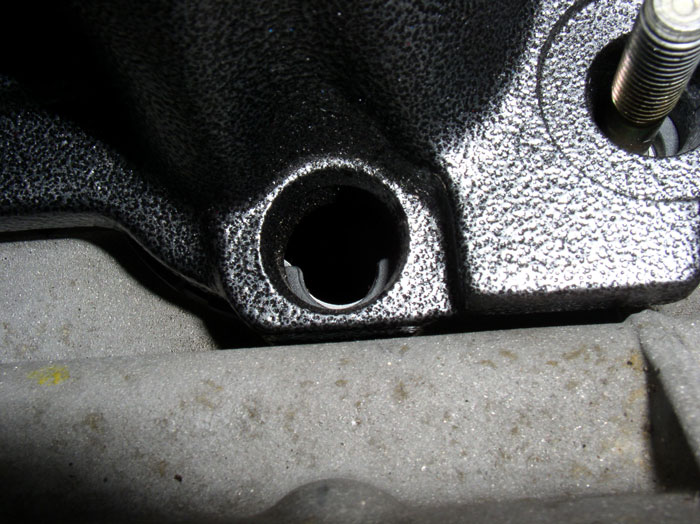
The bolts are designed to "bottom out" on the bolt shoulder at the top of the threads (see below). Hence the low torque values required (7 ftlbs).
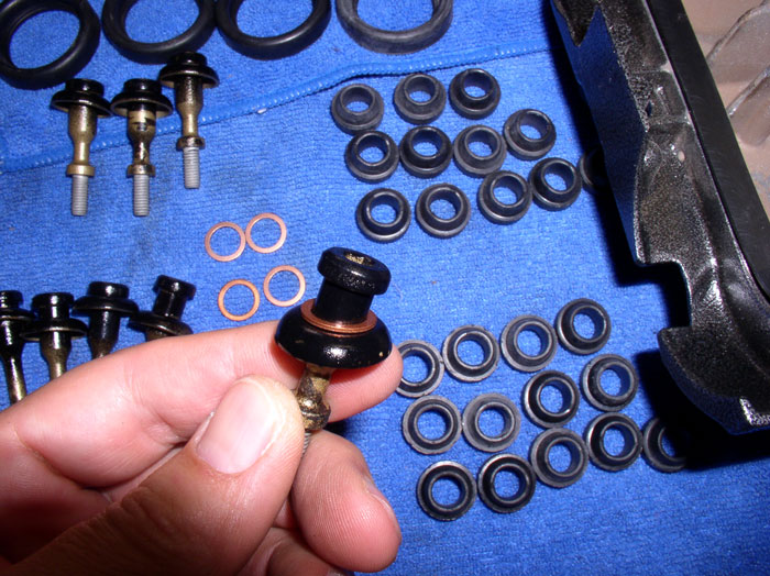
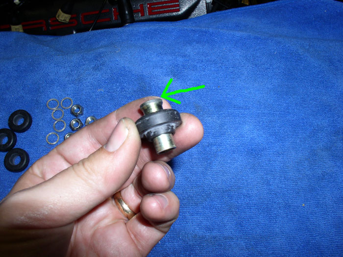
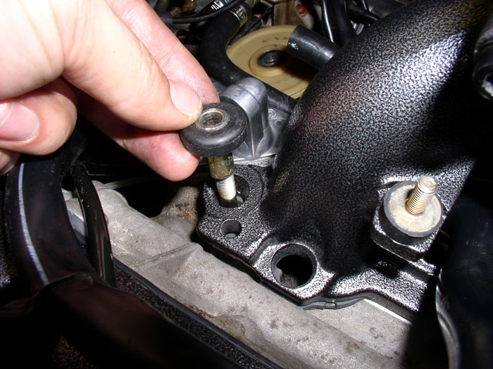
By introducing additional space between the head of the bolt and the umbrella washer (using the sealing ring pictured above) the distance to "bottom out" the shoulder against the cylinder head is effectively lengthened - giving you a turn or two more of force that is applied to the rubber thrust washer that is not available on the bolts without the sealing ring. The additional force exerted on the rubber thrust washer is transferred and distributed across the bottom edge of the cam cover (where the sealing rings are used) - see below.
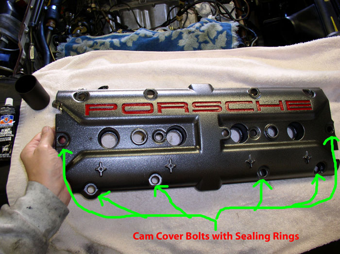
Since more oil pools at the bottom edge of the cam cover than at the top edge of the cam cover (due to gravity) additional clamping force helps seal the cam cover gasket and prevent premature leaking across the bottom of the cam cover. Since the heads and cam covers are tilted, it creates an assymetric oil pooling condition under the cam cover. The use of the sealing rings across the bottom as pictured above provides an assymetric clamping solution to effectively deal with the condition without designing special bolts or using twice the number of sealing rings that aren't needed on the other bolts on the cam cover. Thinking about it - pretty nifty, low cost solution.
But enough thinking and back to wrenching!
01-31-2009, 12:46 PM
#124
Addict
Rennlist Member
Rennlist Member
Join Date: Oct 2003
Location: Gone. On the Open Road
Posts: 16,322
Received 1,542 Likes
on
1,006 Posts
Not all of the S4 motors have these sealing rings. They are common on '87 and '88, not-so-common on '89 and very uncommon on '90+. It's almost as if they were added to the bottom bolts by the factory only if the engine leaked while the engine dyno test was being done.
01-31-2009, 01:37 PM
#125
Rennlist Member
Thread Starter
Join Date: Sep 2007
Location: Ridgecrest, California
Posts: 1,363
Likes: 0
Received 143 Likes
on
28 Posts
First, some prep work is needed before installing the intake. Position the spark plug wires over the cam covers. The number 4 plug wire is fed under the plug wire guide on the passenger side engine lift hook at the front of the engine. See below.
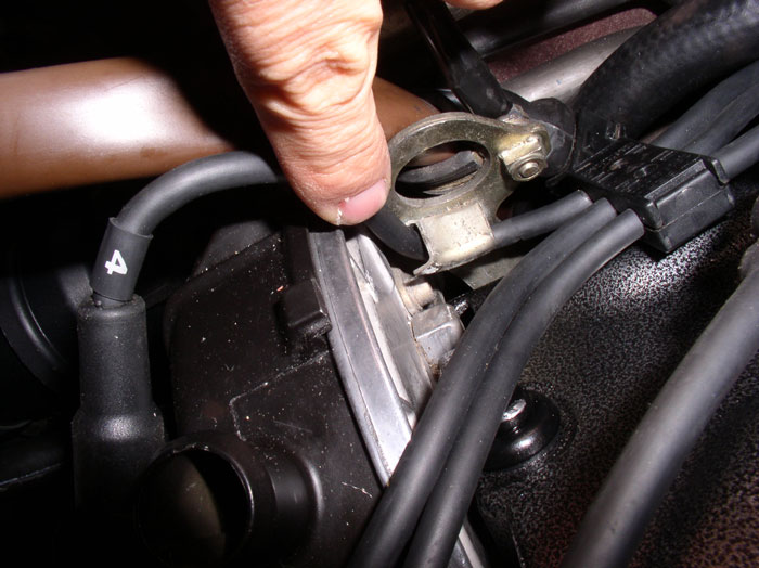
Since we did not disconnect the plug wires from the distributor, matching up the plug wires to their respective cylinders is straight forward (my plug wires were also numbered). The length of the wires will help determine which plug they go to. You can confirm the wire matches the correct spark plug by looking at distributor spark plug map typically located on a decal on top of the radiator. Position the plug end of the wires into the spark plug holes in the cam cover.
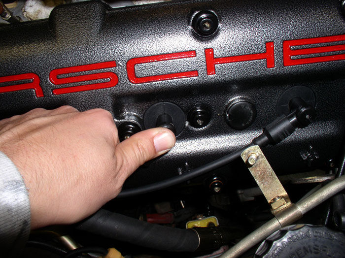
Once you've matched all the wires up to their respective spark plugs and confirmed the matching, press them into place until you hear/feel a solid "click". The plug gasket should be flush with the top of the cam cover as shown. At this time, you can attach the spark plug wiring harness to the harness bracket on the cam covers. However, I have left mine off for now since it makes it a lot easier to move the spark plug wires around if additional tweaking is needed before wrapping up this job. I plan to install the harness brackets on the cam covers and attache the spark plug harness later on (when I'm done goofing around under the hood).
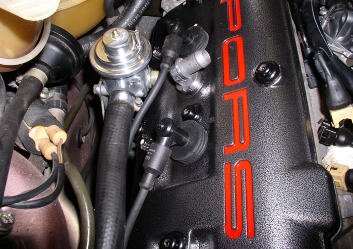
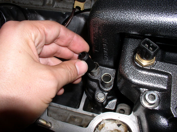
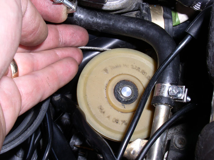
Next, install the one-way PCV valve in the rear port of the oil filler neck. I checked the operation of the valve by simply blowing on each end. Air should flow in one direction through the valve but not in the other direction. Oh yea, good idea to clean the valve before putting it in your mouth.
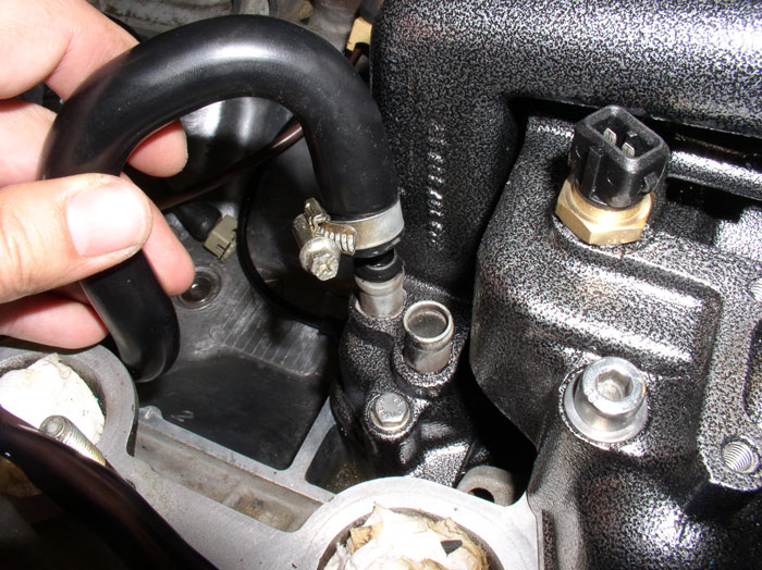
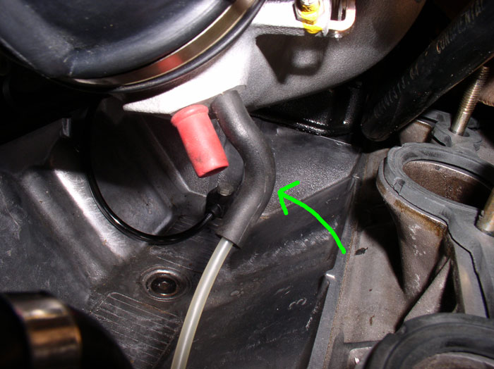
Install the long PCV hose onto the rear oil filler neck port. The other end of this hose connects to the Air Cowl Guide which will be connected shortly. Position the hose as shown, it should be oriented so that runs parallel to and follows the inside edge of the cylinder head. Tighten the clamp.
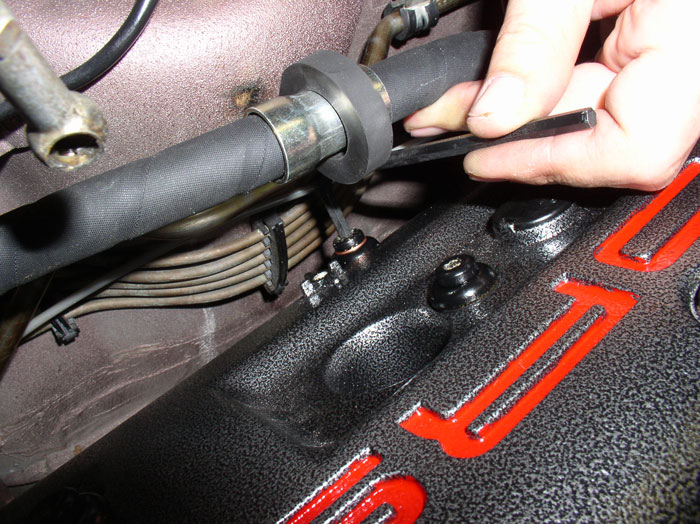
Next, attach the cam cover breather hose to the front oil filler neck port as shown. Position this hose so that the other end connects to the front breather elbow on the cam cover without binding the hose at the oil filler neck. Don't connect/clamp the end at the cam cover elbow yet. You can tighten the clamp on the breather hose at the filler neck by using a long screw driver or socket extension as shown.
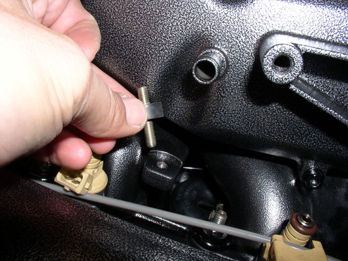
Since my fuel rail mounting studs on the intake were toast, I ordered new ones. I installed these next. The longer stud is threaded into the intake while the shorter end of the stud should be facing upward to mount the fuel rail. You will not be able to install the fuel rail mounting nuts if the long end of the stud is pointing upward. I also learned from a post on this thread (although I can't find it now) that if these rubber parts harden and fail and break like mine did, there is a possibility that a fuel leak may occur at the injectors which may also lead to an engine fire. I understand that solid metal mounts may be available and could be an alternative mount to use. A matter of personal preference.
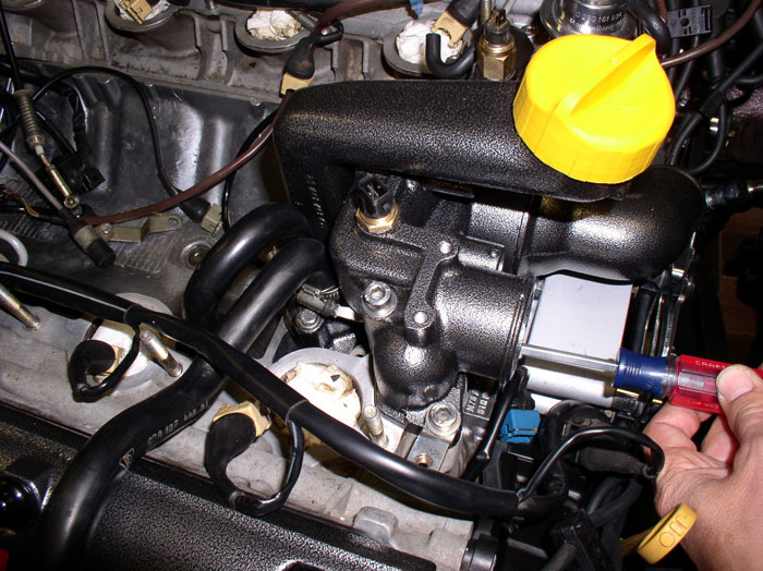
Position the 3-way fuel vapor/oil filler neck/throttle body hose as shown but don't connect just yet.

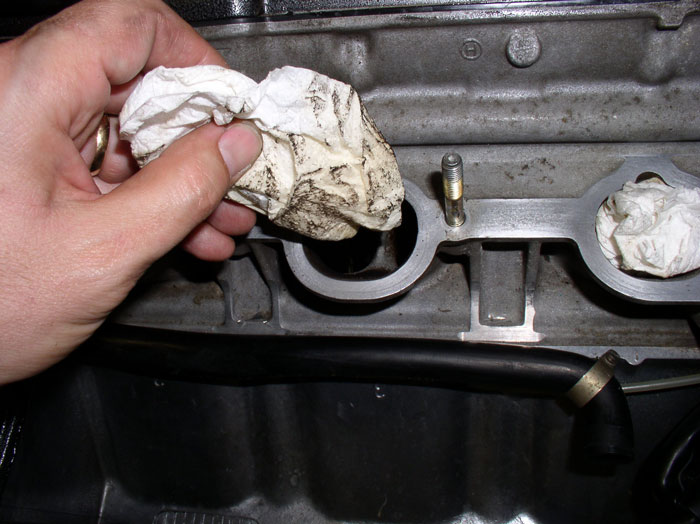
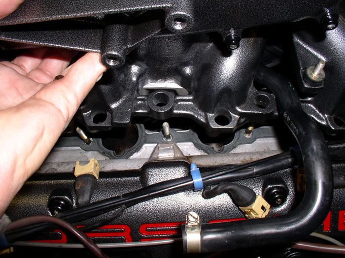
Next, prepare the cylinder head mating surface for the intake by wiping it down and removing any residual debris.
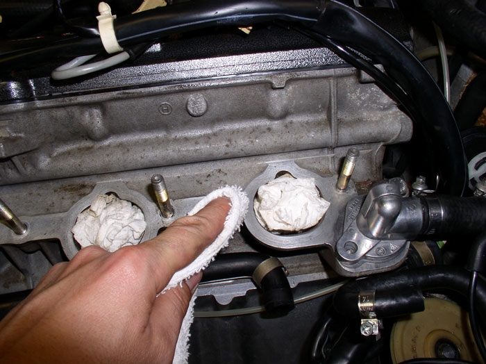
After wiping down the mating surface, remove the rags/plugs in the intake ports. I double checked to ensure nothing foreign made it's way into the cylinder head.
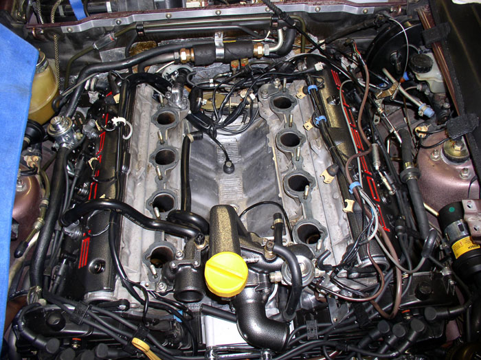
Install the intake rubber gaskets. Ensure they are facing up - there is stamped lettering on the top side (e.g., "TOP"). Also ensure the curved recess for the injector is matched to the same recess in the mating surface of the cylinder head as shown.
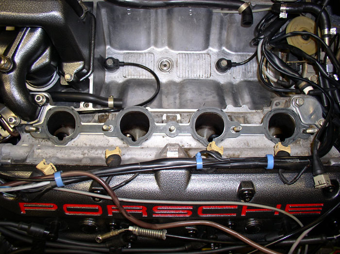
Install the other gasket. Now, it's ready to bring the intake/throttle body assembly over and should look something like this.
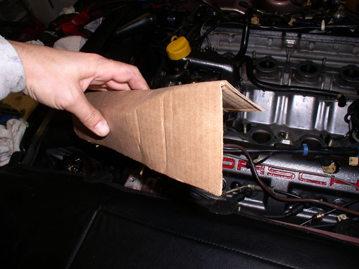
To help with keeping the intake elevated while making some underneath connections, I used cardboard strips (about 8" wide and 12-18" long). Bend the cardboard strips lenthwise as shown creating appoximately a 3X2X3 "U" shape.
Place the cardboard "U" shaped stands inverted over the intake mounting studs as shown.
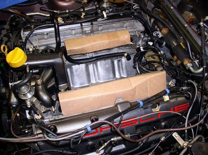
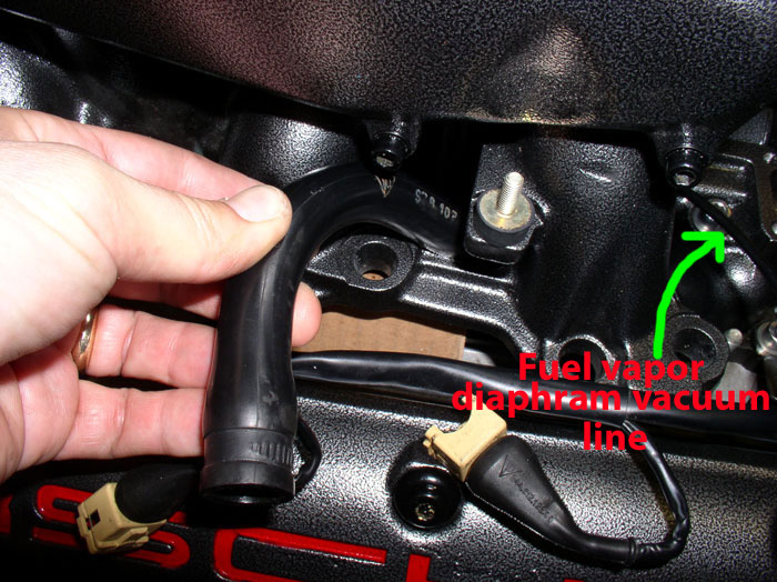
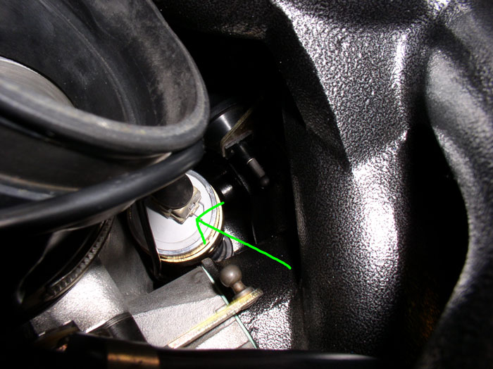
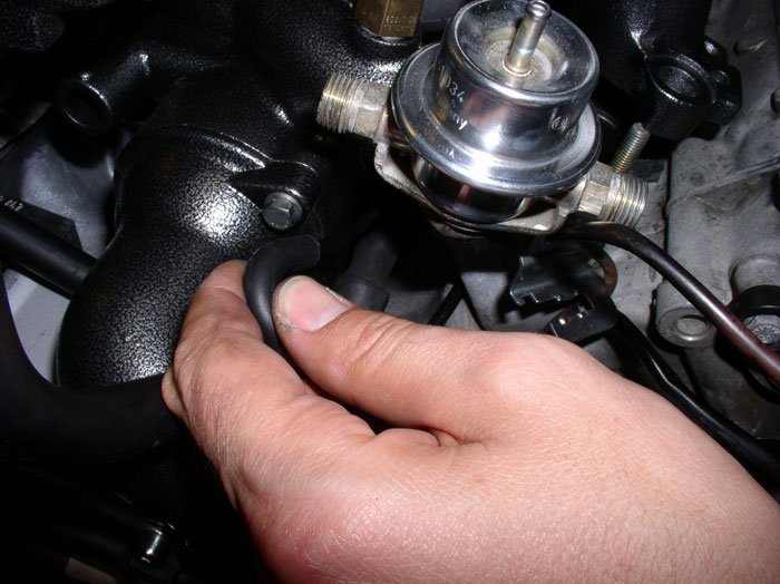
Then bring the intake/throttle body assembly over and set it on the cardboard "stands". Next, lift up the passenger side of the intake and route the front cam cover breather hose through the gap between the first two intake runner legs as shown. Then grasp the fuel vapor diaphram vacuum line (see arrow) and route it through the first two intake runner legs as well.
continued......
Since we did not disconnect the plug wires from the distributor, matching up the plug wires to their respective cylinders is straight forward (my plug wires were also numbered). The length of the wires will help determine which plug they go to. You can confirm the wire matches the correct spark plug by looking at distributor spark plug map typically located on a decal on top of the radiator. Position the plug end of the wires into the spark plug holes in the cam cover.
Once you've matched all the wires up to their respective spark plugs and confirmed the matching, press them into place until you hear/feel a solid "click". The plug gasket should be flush with the top of the cam cover as shown. At this time, you can attach the spark plug wiring harness to the harness bracket on the cam covers. However, I have left mine off for now since it makes it a lot easier to move the spark plug wires around if additional tweaking is needed before wrapping up this job. I plan to install the harness brackets on the cam covers and attache the spark plug harness later on (when I'm done goofing around under the hood).
Next, install the one-way PCV valve in the rear port of the oil filler neck. I checked the operation of the valve by simply blowing on each end. Air should flow in one direction through the valve but not in the other direction. Oh yea, good idea to clean the valve before putting it in your mouth.
Install the long PCV hose onto the rear oil filler neck port. The other end of this hose connects to the Air Cowl Guide which will be connected shortly. Position the hose as shown, it should be oriented so that runs parallel to and follows the inside edge of the cylinder head. Tighten the clamp.
Next, attach the cam cover breather hose to the front oil filler neck port as shown. Position this hose so that the other end connects to the front breather elbow on the cam cover without binding the hose at the oil filler neck. Don't connect/clamp the end at the cam cover elbow yet. You can tighten the clamp on the breather hose at the filler neck by using a long screw driver or socket extension as shown.
Since my fuel rail mounting studs on the intake were toast, I ordered new ones. I installed these next. The longer stud is threaded into the intake while the shorter end of the stud should be facing upward to mount the fuel rail. You will not be able to install the fuel rail mounting nuts if the long end of the stud is pointing upward. I also learned from a post on this thread (although I can't find it now) that if these rubber parts harden and fail and break like mine did, there is a possibility that a fuel leak may occur at the injectors which may also lead to an engine fire. I understand that solid metal mounts may be available and could be an alternative mount to use. A matter of personal preference.
Position the 3-way fuel vapor/oil filler neck/throttle body hose as shown but don't connect just yet.
Next, prepare the cylinder head mating surface for the intake by wiping it down and removing any residual debris.
After wiping down the mating surface, remove the rags/plugs in the intake ports. I double checked to ensure nothing foreign made it's way into the cylinder head.
Install the intake rubber gaskets. Ensure they are facing up - there is stamped lettering on the top side (e.g., "TOP"). Also ensure the curved recess for the injector is matched to the same recess in the mating surface of the cylinder head as shown.
Install the other gasket. Now, it's ready to bring the intake/throttle body assembly over and should look something like this.
To help with keeping the intake elevated while making some underneath connections, I used cardboard strips (about 8" wide and 12-18" long). Bend the cardboard strips lenthwise as shown creating appoximately a 3X2X3 "U" shape.
Place the cardboard "U" shaped stands inverted over the intake mounting studs as shown.
Then bring the intake/throttle body assembly over and set it on the cardboard "stands". Next, lift up the passenger side of the intake and route the front cam cover breather hose through the gap between the first two intake runner legs as shown. Then grasp the fuel vapor diaphram vacuum line (see arrow) and route it through the first two intake runner legs as well.
continued......
01-31-2009, 02:38 PM
#126
Rennlist Member
Thread Starter
Join Date: Sep 2007
Location: Ridgecrest, California
Posts: 1,363
Likes: 0
Received 143 Likes
on
28 Posts
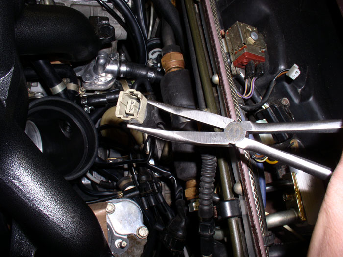
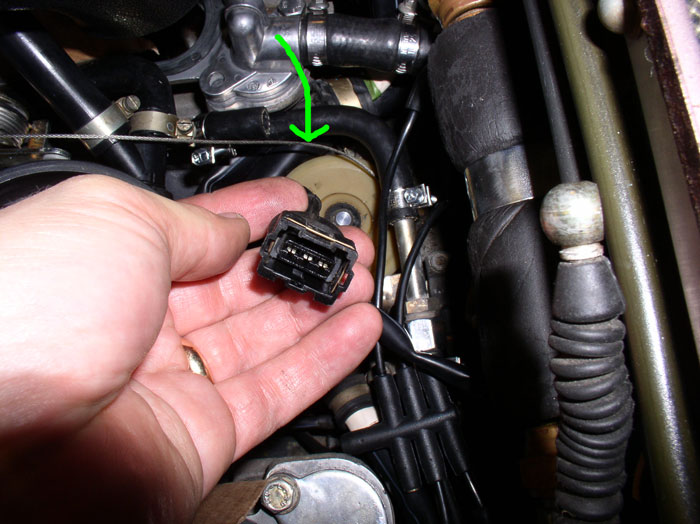
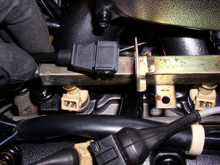
Next, connect the Idle Stabilization Valve (ISV) electrical plug. I used an extra long pair of 90 degree needle nose pliers to grip the plug end. Then rotate the intake so you can gain visual access to the ISV end of the connection. I rotated the intake toward the driver's side of the car since I'm right handed. The plug connection is keyed so you will need to position the plug end in the pliers to match the keyed receptacle at the ISV. Then, manuever the needle nose pliers under the intake and carefully line up the keyed plug and press into place. Be careful not to squeeze the connector with the pliers too hard as it may be brittle and break. I actually broke a corner off the plug (I think it was the 3rd time I removed the intake on this job when I chipped the connector! It still holds just fine).
The wire connection should look like this when connected.
Next, rotate the intake back to normal and lift up the driver's side to gain access to the throttle body. Connect the 3-way fuel vapor/oil filler neck/throttle body hose to the port on the bottom of the throttle body as shown. Position the clamp as shown and tighen down.
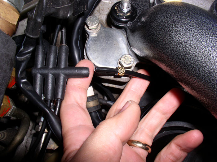
While you're on the driver's side, locate the Throttle Postion Sensor (TPS) harness connector as shown. Also note the throttle plate cable at the wheel shown by the arrow in the picture. It most certainly has come off the wheel during this repair. Don't worry about threading the cable on the wheel just yet, we'll get to that. But make sure the cable is accessible.
Connect the TPS harness plug to the TPS on the side of the throttle body.
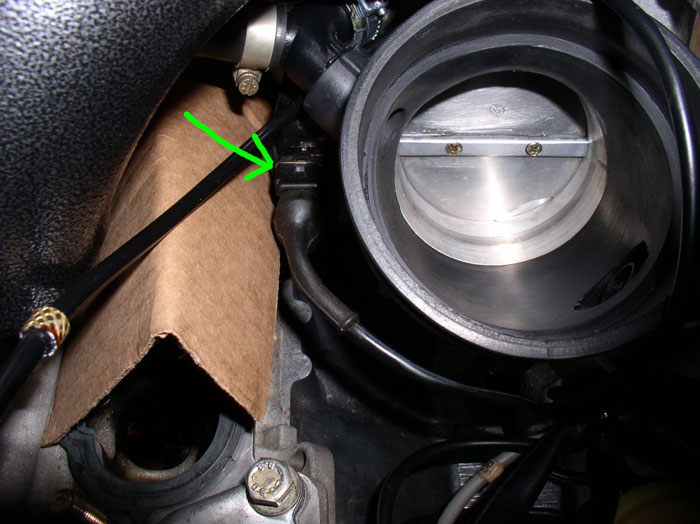
Move to the front of the intake, driver's side and manuever the flappy valve vacuum line through the opening under the water bridge
Next, move over to the passenger side and lift up the intake. Connect the long PCV hose that runs to the rear port of the oil filler neck, to the "Y" connector attached to the Air Guide Cowl.
Position the clamp as shown and tighten down.
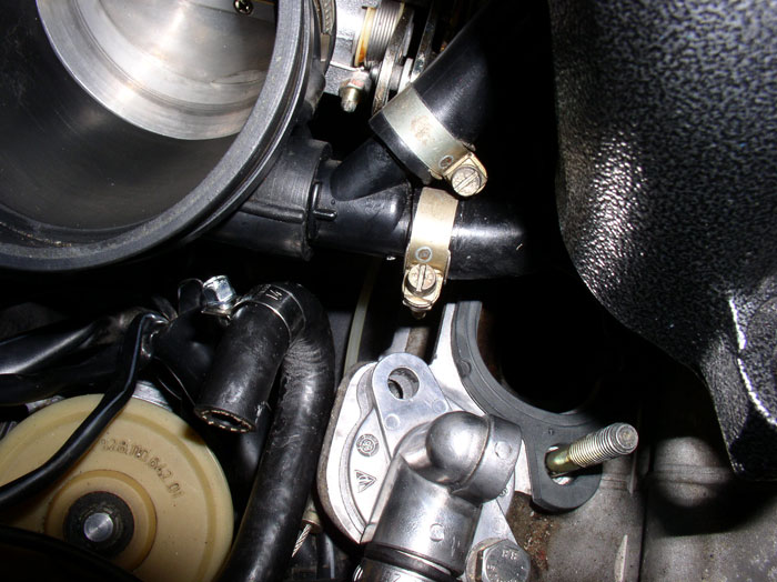
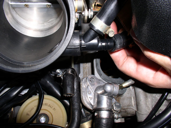
Then, connect the air diverter valve vacuum line elbow to the open port on the bottom of the throttle body as shown.
Next, locate the end of the throttle plate cable and ensure it is not obstructed or wrapped around any hoses/wires. I placed a moderate amount of black grease in the the ball cap before installation.
Press the ball cap end of the cable onto the ball at the throttle plate lever arm as shown.
Next, remove the cardboard and lower the intake over the mounting studs.
Thread the throttle plate cable around the cable wheel as shown. Pull the other end of the cable to ensure the throttle plate and cable operate smoothly througout its range.
Ensure the recessed cutout in the intake gasket for the fuel injectors lines up with the recessed cutout in the cylinder head and is centered in the fuel injector hole.
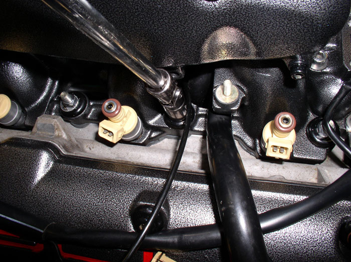
On the passenger side, route the two cam cover breather hoses and fuel vapor diaphram vacuum line (see arrows) so they are UNDER the fuel injector wiring harness - they are still on top of the harness in this picture.
continued....
The wire connection should look like this when connected.
Next, rotate the intake back to normal and lift up the driver's side to gain access to the throttle body. Connect the 3-way fuel vapor/oil filler neck/throttle body hose to the port on the bottom of the throttle body as shown. Position the clamp as shown and tighen down.
While you're on the driver's side, locate the Throttle Postion Sensor (TPS) harness connector as shown. Also note the throttle plate cable at the wheel shown by the arrow in the picture. It most certainly has come off the wheel during this repair. Don't worry about threading the cable on the wheel just yet, we'll get to that. But make sure the cable is accessible.
Connect the TPS harness plug to the TPS on the side of the throttle body.
Move to the front of the intake, driver's side and manuever the flappy valve vacuum line through the opening under the water bridge
Next, move over to the passenger side and lift up the intake. Connect the long PCV hose that runs to the rear port of the oil filler neck, to the "Y" connector attached to the Air Guide Cowl.
Position the clamp as shown and tighten down.
Then, connect the air diverter valve vacuum line elbow to the open port on the bottom of the throttle body as shown.
Next, locate the end of the throttle plate cable and ensure it is not obstructed or wrapped around any hoses/wires. I placed a moderate amount of black grease in the the ball cap before installation.
Press the ball cap end of the cable onto the ball at the throttle plate lever arm as shown.
Next, remove the cardboard and lower the intake over the mounting studs.
Thread the throttle plate cable around the cable wheel as shown. Pull the other end of the cable to ensure the throttle plate and cable operate smoothly througout its range.
Ensure the recessed cutout in the intake gasket for the fuel injectors lines up with the recessed cutout in the cylinder head and is centered in the fuel injector hole.
On the passenger side, route the two cam cover breather hoses and fuel vapor diaphram vacuum line (see arrows) so they are UNDER the fuel injector wiring harness - they are still on top of the harness in this picture.
continued....
01-31-2009, 02:45 PM
#127
Rennlist Member
If there was a hall of fame for R-list posters, you'd be in it Dwayne, and as the fastest inductee in HOF history! Your posts are awesome.
The following users liked this post:
coach928 (03-26-2021)
01-31-2009, 03:30 PM
#128
Rennlist Member
Thread Starter
Join Date: Sep 2007
Location: Ridgecrest, California
Posts: 1,363
Likes: 0
Received 143 Likes
on
28 Posts
Next, prepare the mounting hardward for the intake. You should have 10 each of the following: metal sleeves, new rubber thrust washers, metal umbrella washers and locking 13mm nuts. There are a couple of ways to install the metal sleeve - flange up or flange down. If yours was installed with flange down when you removed it (like mine was), you may decide you want to install the metal sleeve in the same orientation on this install. You will need to install the metal sleeve from underneath the intake with flange oriented down. Then install the rubber thrust washer on the top of the metal sleeve to hold it in place in the intake. Now you can lower the intake over the studs.
However, when I looked in the PET and tech bulletin #8701 from the 1984-1993 tech bulletins on CD, the diagrams seemed to indicate the order of the sleeve and thrust washer installation - thrust washer first then sleeve then umbrella washer then lock nut. See post 160 of this thread for more details. Based on this observation, I decided to install the sleeve with flange oriented up. If you decide to go this route as well, you can follow the next pictures and steps for installation (I believe the sleeve will function the same regardless if the flange is oriented up or down so it may be more a matter of preference). Insert the sleeve into the rubber thrust washer with the flange oriented on top of the washer as shown. There was a recessed groove in the top of the thrust washers I received to accomodate the flange on the sleeve.
Install the rubber thrust washer and sleeve onto the intake mounting studs.
Place the umbrella washer on next.
Since my injectors were sent out for cleaning and were separated from the fuel rail, I test fit them in the injector holes before installing and torquing down the intake nuts. This served two side benefits, it plugged the injector hole to prevent debris from falling into the cylinder head and second, it helped me ensure the injectors would fit properly and line up with the gasket underneath before torquing the intake down. Install the 13mm locknut on the studs and begin torquing them down. Torque to 11 ftlbs. I started in the middle of the intake and worked outward and side to side (driver's vs passenger side). HOWEVER, do not install and torque down the rear (toward the firewall) nut on each side of the intake - you will need to install the fuel pressure damper/regulator assembly on this stud before installing the nut and torquing down.
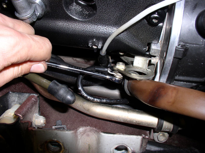
For the harder to reach nuts, you will need to use a universal elbow joint with your torque wrench.
On the passenger side, I needed to remove the intake side cover plate allen head bolt just above the intake mounting stud in order to get the socket on the 13mm nut. The allen head bolt is 5mm.
Torque the 13mm nut under the allen head bolt down and re-install the 5mm allen head bolt into the side cover plate.
I replaced my 7-port vacuum manifold at the back of the engine with a new one. If you do the same, simply transfer the vacuum lines from the old manifold one at a time to the new manifold. I also had two metal plugs to transfer since two ports are not used. Then connect the vacuum line from the throttle body to the inlet port of the vacuum manifold as shown.
Next, I placed the passenger side fuel rail on top of the injectors (without pressure) to do a fit check on the rear knock sensor. Ensure the knock sensor connector will reach the plug bracket on top of the fuel rail. It was at this time I noticed the new plug on the new knock sensor would not fit into the bracket on the fuel rail. After some time trying to make it fit with no success, I decided not to use the fuel rail bracket but did ensure there was enough slack in the knock sensor wire to connect to the wiring harness receptacle and would tuck the connection between the fuel rail and intake runners.
Next, I worked on the insulation on the fuel rails. My original insulation was completely missing. I came across a post here on this great 928 forum about someone that used pipe insulation as an alternative to the fuel rail insulation as I understand the fuel rail insulation is no longer available. I wish I could remember who it was because they deserve the credit for this idea. I went to Home Depot and bought 3/4" inside diameter pipe insulation and cut it down to the length required to cover the fuel rail.
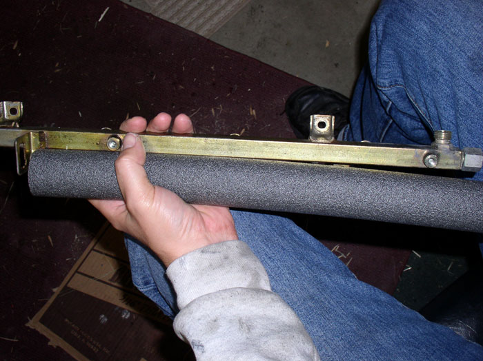
Wrap the insulation around the fuel rail so the ends meet on the underside.
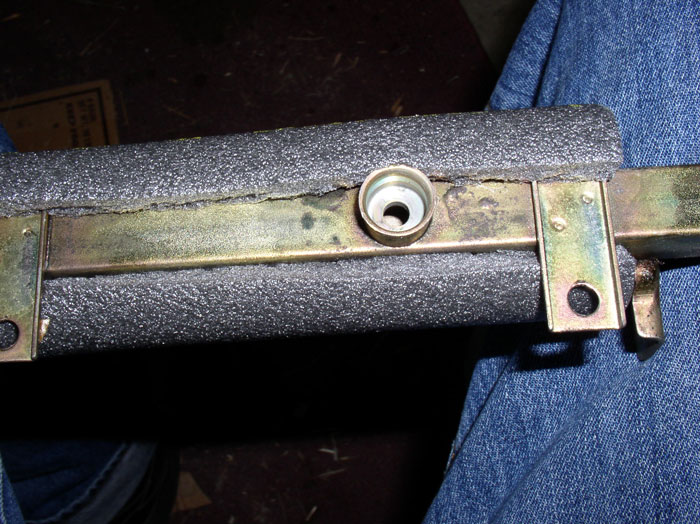
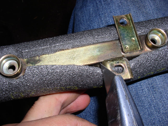
Use a utility knife to carefully cut around the injector openings and the mounting tabs on the fuel rail. Flip the fuel rail over and cut out the openings in the top of the rail for the fuel rail plastic covers mounting holes.
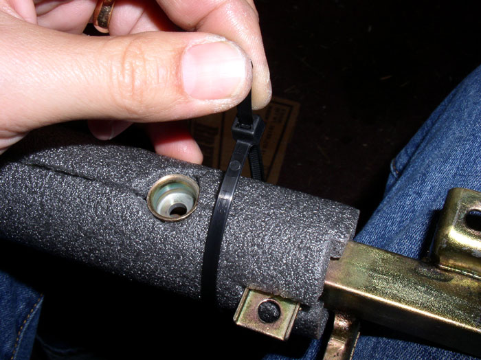
Use zip ties for securing the insulation to the fuel rail.
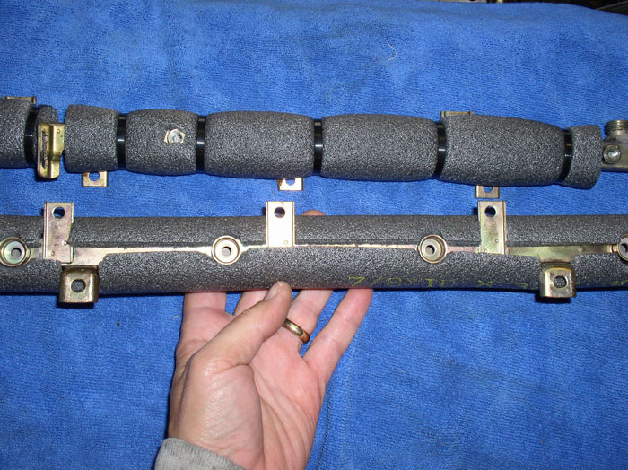
Do the same procedure on the other fuel rail. When complete, it should look something like this. I found that the fuel rail plastic covers will fit snuggly on the fuel rails with this insulation, at first. After a time, the insulation conforms to the square pattern of the rail and the cover and fits nicely. I can't say that I've noticed significant noise reduction on the injector clicking, though. Too bad I don't have an instrument to measure the sound before and after the insulation installation.
continued.....
However, when I looked in the PET and tech bulletin #8701 from the 1984-1993 tech bulletins on CD, the diagrams seemed to indicate the order of the sleeve and thrust washer installation - thrust washer first then sleeve then umbrella washer then lock nut. See post 160 of this thread for more details. Based on this observation, I decided to install the sleeve with flange oriented up. If you decide to go this route as well, you can follow the next pictures and steps for installation (I believe the sleeve will function the same regardless if the flange is oriented up or down so it may be more a matter of preference). Insert the sleeve into the rubber thrust washer with the flange oriented on top of the washer as shown. There was a recessed groove in the top of the thrust washers I received to accomodate the flange on the sleeve.
Install the rubber thrust washer and sleeve onto the intake mounting studs.
Place the umbrella washer on next.
Since my injectors were sent out for cleaning and were separated from the fuel rail, I test fit them in the injector holes before installing and torquing down the intake nuts. This served two side benefits, it plugged the injector hole to prevent debris from falling into the cylinder head and second, it helped me ensure the injectors would fit properly and line up with the gasket underneath before torquing the intake down. Install the 13mm locknut on the studs and begin torquing them down. Torque to 11 ftlbs. I started in the middle of the intake and worked outward and side to side (driver's vs passenger side). HOWEVER, do not install and torque down the rear (toward the firewall) nut on each side of the intake - you will need to install the fuel pressure damper/regulator assembly on this stud before installing the nut and torquing down.
For the harder to reach nuts, you will need to use a universal elbow joint with your torque wrench.
On the passenger side, I needed to remove the intake side cover plate allen head bolt just above the intake mounting stud in order to get the socket on the 13mm nut. The allen head bolt is 5mm.
Torque the 13mm nut under the allen head bolt down and re-install the 5mm allen head bolt into the side cover plate.
I replaced my 7-port vacuum manifold at the back of the engine with a new one. If you do the same, simply transfer the vacuum lines from the old manifold one at a time to the new manifold. I also had two metal plugs to transfer since two ports are not used. Then connect the vacuum line from the throttle body to the inlet port of the vacuum manifold as shown.
Next, I placed the passenger side fuel rail on top of the injectors (without pressure) to do a fit check on the rear knock sensor. Ensure the knock sensor connector will reach the plug bracket on top of the fuel rail. It was at this time I noticed the new plug on the new knock sensor would not fit into the bracket on the fuel rail. After some time trying to make it fit with no success, I decided not to use the fuel rail bracket but did ensure there was enough slack in the knock sensor wire to connect to the wiring harness receptacle and would tuck the connection between the fuel rail and intake runners.
Next, I worked on the insulation on the fuel rails. My original insulation was completely missing. I came across a post here on this great 928 forum about someone that used pipe insulation as an alternative to the fuel rail insulation as I understand the fuel rail insulation is no longer available. I wish I could remember who it was because they deserve the credit for this idea.
I went to Home Depot and bought 3/4" inside diameter pipe insulation and cut it down to the length required to cover the fuel rail.Wrap the insulation around the fuel rail so the ends meet on the underside.
Use a utility knife to carefully cut around the injector openings and the mounting tabs on the fuel rail. Flip the fuel rail over and cut out the openings in the top of the rail for the fuel rail plastic covers mounting holes.
Use zip ties for securing the insulation to the fuel rail.
Do the same procedure on the other fuel rail. When complete, it should look something like this. I found that the fuel rail plastic covers will fit snuggly on the fuel rails with this insulation, at first. After a time, the insulation conforms to the square pattern of the rail and the cover and fits nicely. I can't say that I've noticed significant noise reduction on the injector clicking, though. Too bad I don't have an instrument to measure the sound before and after the insulation installation.
continued.....
Last edited by Dwayne; 03-17-2009 at 01:25 AM.
01-31-2009, 05:28 PM
#129
Rennlist Member
Thread Starter
Join Date: Sep 2007
Location: Ridgecrest, California
Posts: 1,363
Likes: 0
Received 143 Likes
on
28 Posts
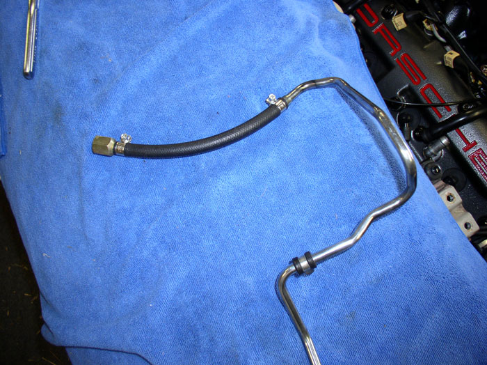
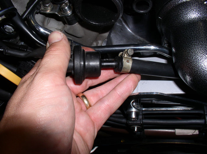
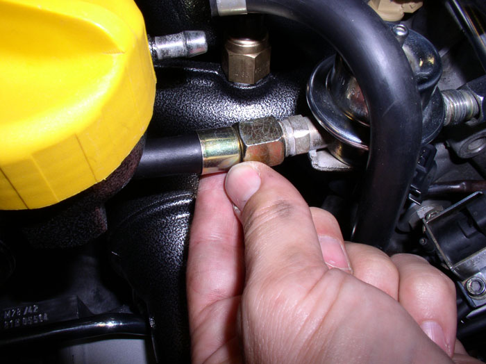
Next, make some fuel line connections before installing the fuel rails. If you haven't already repaired/replaced the fuel hose on the front fuel supply line and you purchased one of Roger's fuel line kits, now's the time to make the repair. You can cut the existing hose off the end connectors using a utility knife. Be carefull to not cut too hard/deeply that you score the metal barbs underneath.
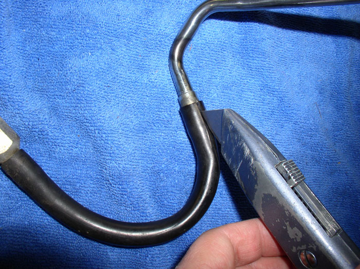
Peel back the rubber hose with a screwdriver after cutting and you should be able to pull the hose off the barbed connectors. Both ends of the fuel line connectors should look like this when the hose is removed.
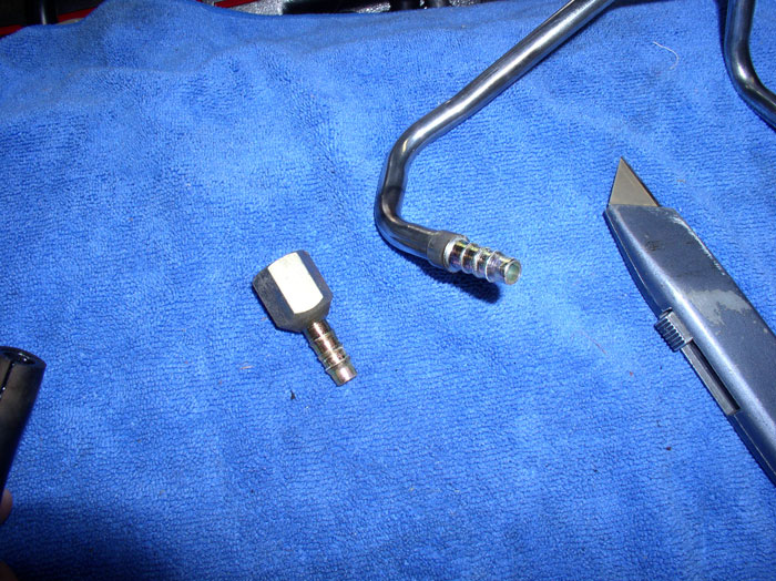
Measure out and cut the same length of new hose from Roger's kit.
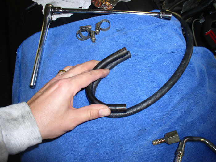
Attach the fuel line nut to one end of the new hose but don't tighten the clamp yet.
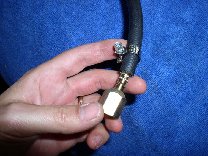
Attach the other end of the hose (dont' forget the 2nd clamp) to the metal fuel line. The new fuel hose had a natural bend to it so it worked best to orient the fuel hose so that it bends in the same direction when installed. You can get the orientation correct by test fitting the assembly to make sure the hose orientation and clamps are positioned correctly. I positioned the clamps so they face inward on the inner radius of the bend as shown. Then tighten down the hose clamps.
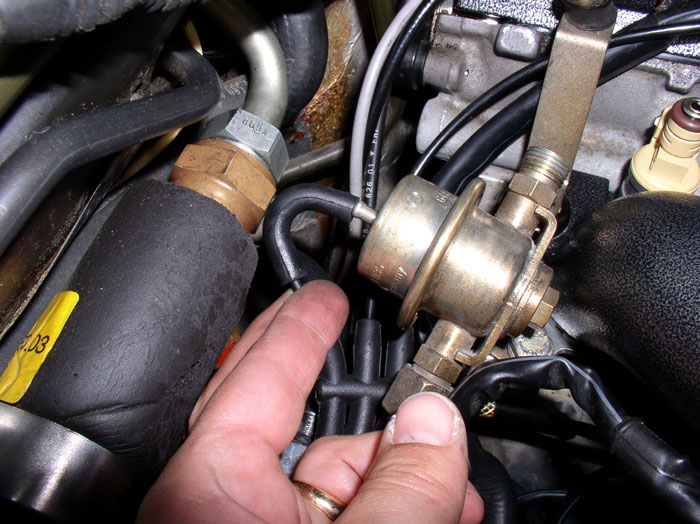
Manuever the Fuel Pressure Damper (FPD) end of the fuel line under the radiator hose elbow attached to the water bridge as shown. Ensure the fuel line is under the wiring harness as shown by the left arrow.
Position the fuel line so you can connect the nut on the fuel line to the bottom of the FPD. Don't tighten the nut yet. I waited until the other lines were connected to the FPD before tightening them all down.
Attach the fuel line clamp to the bracket that is located at the front passenger side of the water bridge. It's a 10mm bolt - tighten the bolt down.
Connect the fuel hose to the fuel supply line at the passenger fender well.
Tighten the connection down using a 17mm wrench and a 19mm wrench to counterhold.
Next, attach the front cam cover breather hose to the elbow at the cam cover and tighten the hose clamp.
Do the same for the rear cam cover breather hose and cam cover elbow.
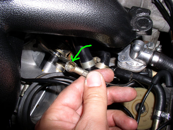
Attach the diverter valve vacuum line elbow to the port on the diverter valve.
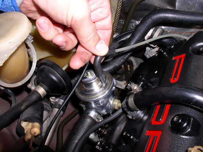
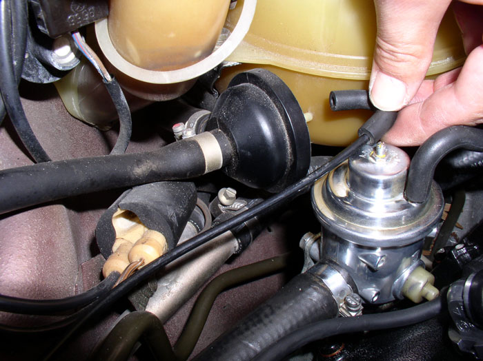
Attach the fuel vapor diaphram vacuum elbow to the port on the diaphram.
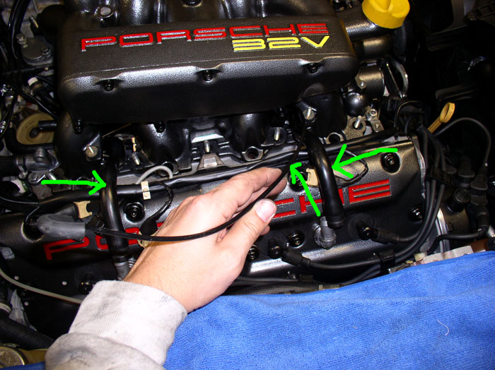
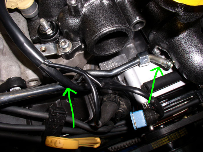
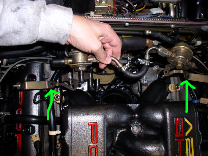
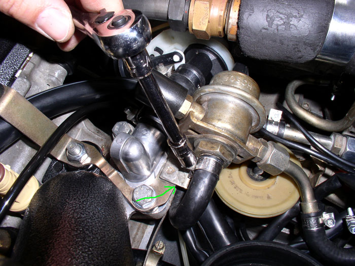
Position the rear FPD/FPR assembly into place at the rear of the engine. Place the mounting bracket holes indicated by the green arrows onto the rear intake mounting studs. The 13mm intake nuts can now be threaded onto the intake mounting studs but don't torque down yet. The other holes in the FPD/FPR assembly brackets should line up with the rear coolant port holes. We'll be installing the 13mm bolts here shortly.
continued.....
Peel back the rubber hose with a screwdriver after cutting and you should be able to pull the hose off the barbed connectors. Both ends of the fuel line connectors should look like this when the hose is removed.
Measure out and cut the same length of new hose from Roger's kit.
Attach the fuel line nut to one end of the new hose but don't tighten the clamp yet.
Attach the other end of the hose (dont' forget the 2nd clamp) to the metal fuel line. The new fuel hose had a natural bend to it so it worked best to orient the fuel hose so that it bends in the same direction when installed. You can get the orientation correct by test fitting the assembly to make sure the hose orientation and clamps are positioned correctly. I positioned the clamps so they face inward on the inner radius of the bend as shown. Then tighten down the hose clamps.
Manuever the Fuel Pressure Damper (FPD) end of the fuel line under the radiator hose elbow attached to the water bridge as shown. Ensure the fuel line is under the wiring harness as shown by the left arrow.
Position the fuel line so you can connect the nut on the fuel line to the bottom of the FPD. Don't tighten the nut yet. I waited until the other lines were connected to the FPD before tightening them all down.
Attach the fuel line clamp to the bracket that is located at the front passenger side of the water bridge. It's a 10mm bolt - tighten the bolt down.
Connect the fuel hose to the fuel supply line at the passenger fender well.
Tighten the connection down using a 17mm wrench and a 19mm wrench to counterhold.
Next, attach the front cam cover breather hose to the elbow at the cam cover and tighten the hose clamp.
Do the same for the rear cam cover breather hose and cam cover elbow.
Attach the diverter valve vacuum line elbow to the port on the diverter valve.
Attach the fuel vapor diaphram vacuum elbow to the port on the diaphram.
Position the rear FPD/FPR assembly into place at the rear of the engine. Place the mounting bracket holes indicated by the green arrows onto the rear intake mounting studs. The 13mm intake nuts can now be threaded onto the intake mounting studs but don't torque down yet. The other holes in the FPD/FPR assembly brackets should line up with the rear coolant port holes. We'll be installing the 13mm bolts here shortly.
continued.....
01-31-2009, 06:23 PM
#130
Rennlist Member
Thread Starter
Join Date: Sep 2007
Location: Ridgecrest, California
Posts: 1,363
Likes: 0
Received 143 Likes
on
28 Posts
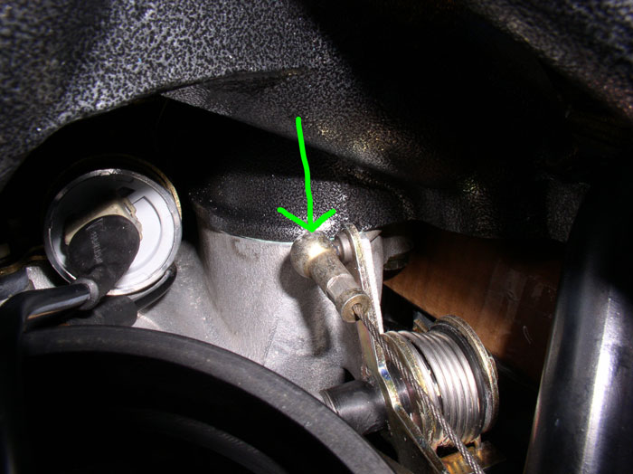
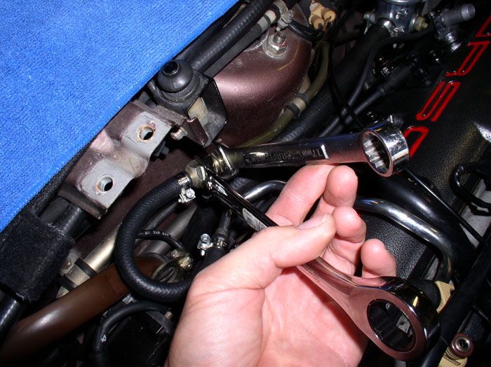
Next, install the 13mm bolt into the rear FPD bracket and into the coolant port threads (see left arrow). Torque down to 16 ftlbs. Then torque down the other 13mm bolt to the coolant port to 16 ftlbs. If the FPD is in the way, you can push it out of the way (push it forward toward the front of the car) because the bracket is fairly flexible. Just push it enough to get the socket on the bolt and torque down. Perform the same operation on the passenger side on the Fuel Pressure Regulator.
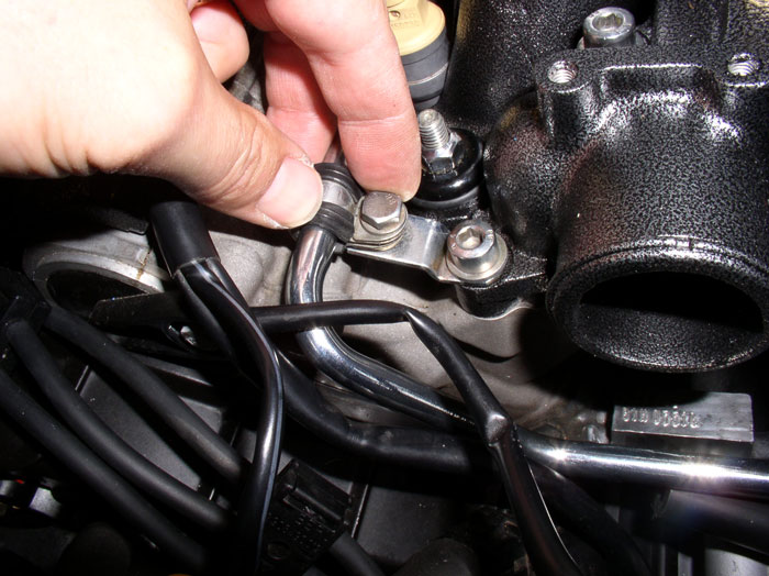
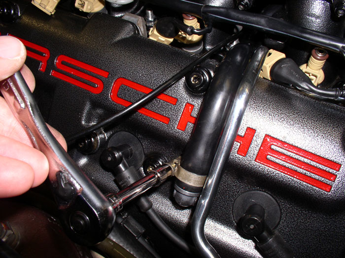
Next, Torque down the 13mm nut on the FPD bracket on the last intake runner stud. Torque to 11 ftlbs. Do the same on the the other side for the FPR.
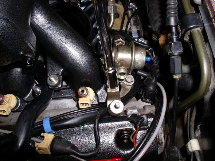
Attach the vacuum elbows and lines to the FPD and FPR.
Connect the fuel return line to the port on the FPR.
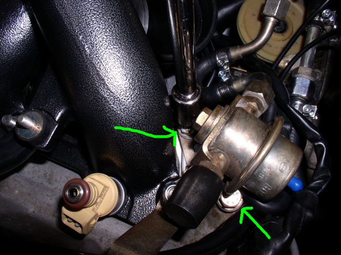
Before tighting the hose clamp, ensure the return hose is inside the fuel hose guide that is attached to the mounting bracket (see green arrow). Ensure the hose is not pinched or in a bind. Then tighten the hose clamp.
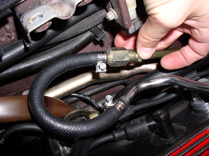
Next, feed the temperature gauge wires under the front FPD and under the water bridge....
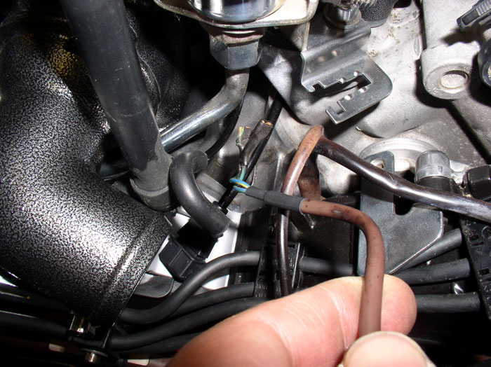
...and up between the water bridge and front of the intake.
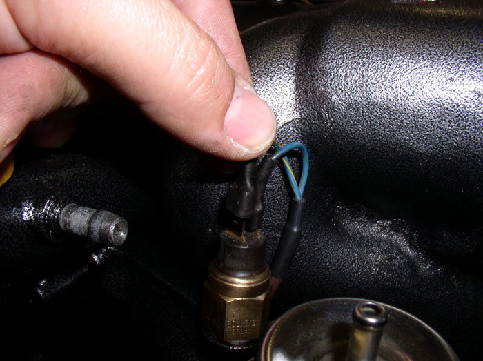
Connect the wires to the sending unit. The connecting blades are of different sizes so simply match up the sizes on the sending unit to the wire connector.
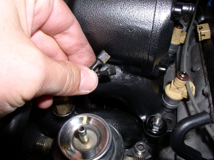
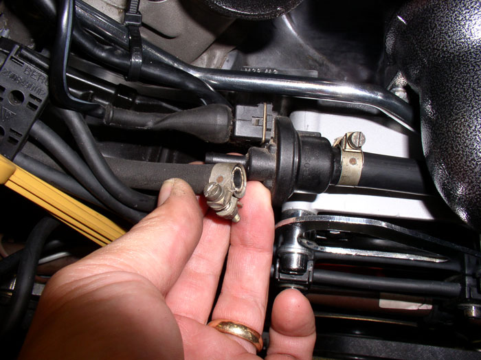
Next, attach the 3-way fuel vapor vent hose to the solenoid at the front of the engine (as shown) and tighten the hose clamp.
Connect the supply hose from the fuel vapor vent diaphram to the solenoid as shown and tighten the hose clamp.
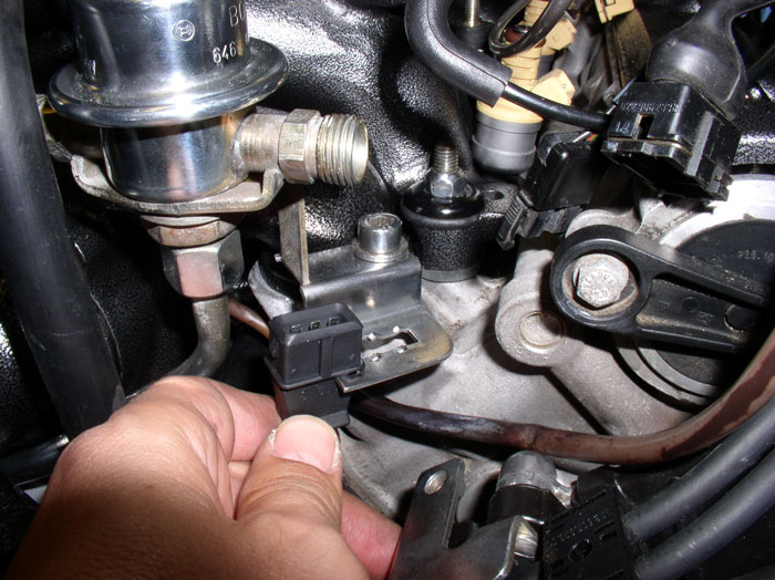
Insert the front knock sensor plug into the plug bracket. It is keyed to go in one way.
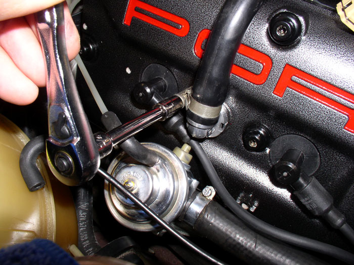
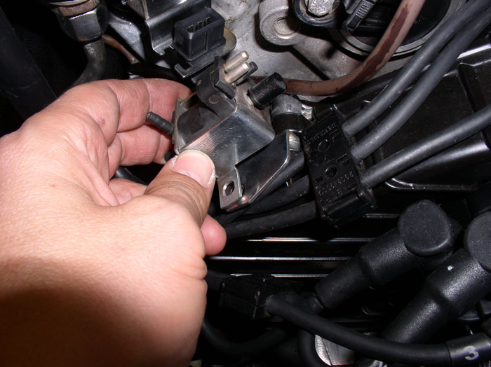
Position the flappy valve vacuum solenoid onto its mounting bracket as shown.
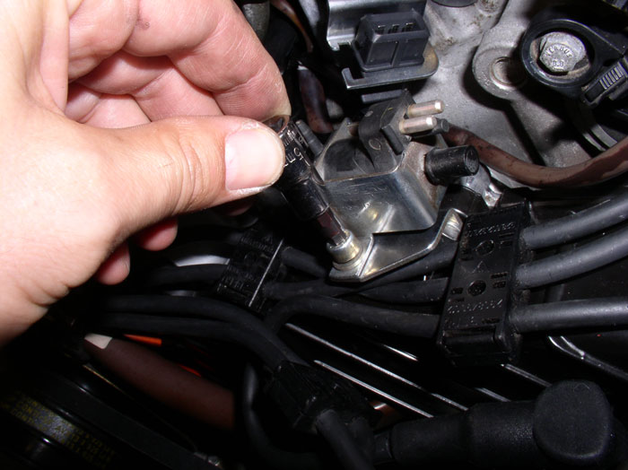
Secure the solenoid to the bracket with the two 5mm allen head bolts.
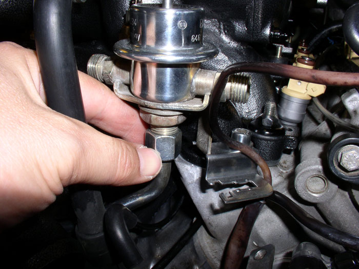
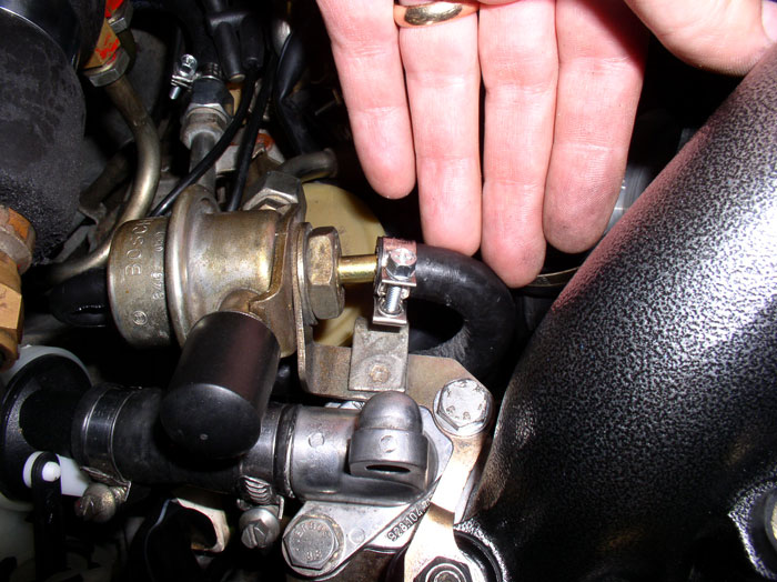
Attach the front fuel hose that runs between the FPD and passenger fuel rail to the front FPD. Tighten down with a 17mm wrench using a 15mm wrench to counterhold.
continued......
Unfortunately, I have to head out of town now and won't be back until next weekend - I'll try to finish this thread then. Fuel rails and injectors are next.
Next, Torque down the 13mm nut on the FPD bracket on the last intake runner stud. Torque to 11 ftlbs. Do the same on the the other side for the FPR.
Attach the vacuum elbows and lines to the FPD and FPR.
Connect the fuel return line to the port on the FPR.
Before tighting the hose clamp, ensure the return hose is inside the fuel hose guide that is attached to the mounting bracket (see green arrow). Ensure the hose is not pinched or in a bind. Then tighten the hose clamp.
Next, feed the temperature gauge wires under the front FPD and under the water bridge....
...and up between the water bridge and front of the intake.
Connect the wires to the sending unit. The connecting blades are of different sizes so simply match up the sizes on the sending unit to the wire connector.
Next, attach the 3-way fuel vapor vent hose to the solenoid at the front of the engine (as shown) and tighten the hose clamp.
Connect the supply hose from the fuel vapor vent diaphram to the solenoid as shown and tighten the hose clamp.
Insert the front knock sensor plug into the plug bracket. It is keyed to go in one way.
Position the flappy valve vacuum solenoid onto its mounting bracket as shown.
Secure the solenoid to the bracket with the two 5mm allen head bolts.
Attach the front fuel hose that runs between the FPD and passenger fuel rail to the front FPD. Tighten down with a 17mm wrench using a 15mm wrench to counterhold.
continued......
Unfortunately, I have to head out of town now and won't be back until next weekend - I'll try to finish this thread then. Fuel rails and injectors are next.
01-31-2009, 08:55 PM
#131
Under the Lift
Lifetime Rennlist
Member
Lifetime Rennlist
Member
This is consistent with my observation that they are not on my virgin 89 nor did I find them on a 90 I worked on.
01-31-2009, 09:25 PM
#133
Under the Lift
Lifetime Rennlist
Member
Lifetime Rennlist
Member
Unfortunately, I have to head out of town now and won't be back until next weekend - I'll try to finish this thread then. Fuel rails and injectors are next.
01-31-2009, 11:18 PM
#134
Rennlist Member
Me thinks the Queen calls him "Sir".

