
Screw it: "Sheet Metal" intakes
 08-05-2008, 05:17 PM
#61
Nordschleife Master
Eric, I had thought about modifying a spider intake as well, but imo would require a Euro S spider to even consider it. And again would be left with a less than optimum TB placement and exit. Basically stuck with the factory location, mainly due to the fact I have my alt attached to the WP, or for a factory engine the oil filler neck. I would like to get away from all those bends as well and rather have one, maybe two TB right up front. And I understand that the 8 sensors would require standalone. But one would be doing standalone anyways to be able to do a sequential injection setup. I already do have standalone on my car as well. So I can mess about with different intake setups very easily without having to worry about making the MAF reach, or having to have alot of stuff to adjust the brain to compensate for the different intake.
Louie, I fully agree with you on the end tanks and the welding of them, with the possibility of setting them on fire and having no way to really put them out would not be something I want to attempt.
I have also considered getting MC TBs of roughly the size needed and just putting them onto the end of the 85/86 runners just to see how they would respond, but again am left with the flow variances in the different tubes causing it to be very uneven. Plus hooking up the throttles would be a PITA! not to mention trying to get a proper MAP signal. I will have to look at those adhesives more closely to see if I can find one that I like enough to consider using. But again would like to get away from those runners due to the uneven flow rates.
The other thought that I have had is doing an intake like the one MA had with the two plenums, and longer runners, but with an equalizing tube between the two.
 08-05-2008, 05:27 PM
#62
Race Director
Heres a pic of the intake on my M3 V8 (4.0L)....it also uses ITB's with drive by wire....the bummer is the intake won't work on a 928 due to its much smaller bore spacing of 98mm vs 122mm on the 928...there is a really good picture of the underneath of the intake, but I can't find it right now (figures)
08-05-2008, 05:30 PM
#63
Nordschleife Master
Brian, I haven't ruled out going the ITBs route on my 86 engine, but it is alot more complex esp to try and hook up.
As well you see less benifit out of ITBs on a boosted engine which is my goal.
As well you see less benifit out of ITBs on a boosted engine which is my goal.
08-05-2008, 07:11 PM
#64
Fleet of Foot
Rennlist Member
Rennlist Member
Thanks Louie. I had forgotten about the harmonics on the 4-on-one-side, so that cuts my "two loafs of bread" idea.
The measuring issue was one I was working on. The 7" on Cylinder one is not alot is it.
A. Graham Bell suggests 300-330mm long runners for a street/track car with a centrifugal. That is from valve seat to bell mouth.
I like this one, but it looks very very tall:

And the runners look very short.
The measuring issue was one I was working on. The 7" on Cylinder one is not alot is it.
A. Graham Bell suggests 300-330mm long runners for a street/track car with a centrifugal. That is from valve seat to bell mouth.
I like this one, but it looks very very tall:
And the runners look very short.
08-05-2008, 07:27 PM
#65
Nordschleife Master
Bill, one of the reasons are we are trying to simplify the tubing, and make it more efficent, by having the throttle body at the rear we would be having to route it to the front or take from the windshield.
08-05-2008, 08:02 PM
#66
Rennlist Member
Thread Starter
 08-05-2008, 08:11 PM
#67
Nordschleife Master
I am pretty sure he was saying to point the TB towards the rear of the car so as to be able to fit something like it under the hood.
If you were to go drysump with the electric waterpump BC, then you could have lots more room up front, that is if you dont put the altenator there like I did.
If you were to go drysump with the electric waterpump BC, then you could have lots more room up front, that is if you dont put the altenator there like I did.
08-05-2008, 10:01 PM
#68
Rennlist Member
Thread Starter
I am pretty sure he was saying to point the TB towards the rear of the car so as to be able to fit something like it under the hood.
If you were to go drysump with the electric waterpump BC, then you could have lots more room up front, that is if you dont put the altenator there like I did.
If you were to go drysump with the electric waterpump BC, then you could have lots more room up front, that is if you dont put the altenator there like I did.

I will stick with the stock WP until you or another has figured out the way to do it with a blank plate on the front that works.
Had another conversation today with Todd in Green Bay. I will go at the engine analyzer again and see what I can find.
08-05-2008, 11:04 PM
#69
Rennlist Member
Thread Starter
I think I can sit easier today:
I figured something out after talking to Todd. Well, Louie, then Todd. And now I understand:
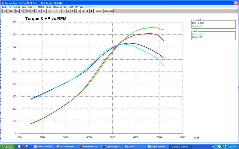
See - the higher graph is with a 3 inch runner intake and the lower one is with 5 inches. Nearly no loss down low, but major gain up top.
I figured something out after talking to Todd. Well, Louie, then Todd. And now I understand:
See - the higher graph is with a 3 inch runner intake and the lower one is with 5 inches. Nearly no loss down low, but major gain up top.
08-05-2008, 11:09 PM
#70
Rennlist Member
Thread Starter
This is with 8 inch runners (plus as always the 4 in the head)
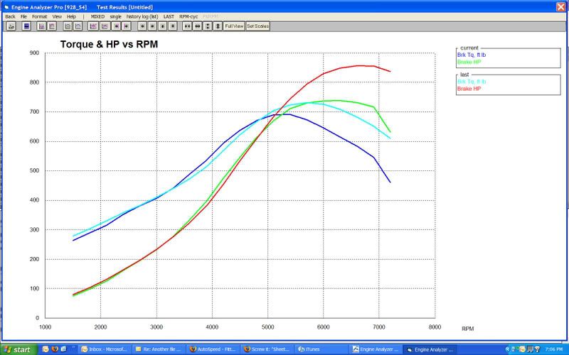
WAY big drop off and not much gained even down low.(Blue and Green is 8 inches, "last" is the shorter runners)
WAY big drop off and not much gained even down low.(Blue and Green is 8 inches, "last" is the shorter runners)
08-05-2008, 11:25 PM
#72
Rennlist Member
Thread Starter
I do change the "intake manifold runner length" So that is the flange of the head to where the bell mouth or major transition would be. So on an S4, its the bell mouth in the side cover to the head face.
Longer does nothing super good lower, but kills top end. By 100s of hp sometimes if its way too long.
I didn't increase the diameter of the runner - just the length. But I also did not change the flow coefficient, as that involves the head port cfm, and I am only trying to hone in on the manifold runner length.
08-05-2008, 11:26 PM
#73
Rennlist Member
Thread Starter
And if this is any indication, 400lbft at 3000rpm is just fine with me.
08-06-2008, 01:18 AM
#74
Nordschleife Master

 08-06-2008, 02:00 AM
#75
Three Wheelin'
The head port length is unchanged, around 4 inches from flange to valve seat. I never change that.
I do change the "intake manifold runner length" So that is the flange of the head to where the bell mouth or major transition would be. So on an S4, its the bell mouth in the side cover to the head face.
Longer does nothing super good lower, but kills top end. By 100s of hp sometimes if its way too long.
I didn't increase the diameter of the runner - just the length. But I also did not change the flow coefficient, as that involves the head port cfm, and I am only trying to hone in on the manifold runner length.
That's about what I found. If you don't care about power above 4000 RPM, then long runners will help down low, but kills it on top. Like a Chev TPI. My ITB runners are short at about 7" from the head. During dyno testing I was worried that they may be too short so I made 2" extensions and expected a big difference. There was nothing. No change. I figured my runners were too short to actually get into resonance so it made little difference whether I had 7" (11" overall) or 9" stacks at the 6500 top RPM I was using. Even when not in resonance, the runners still have a ram effect on the intake charge.
Look at your intake pressure chart in EAP at various RPMs and you will get a better idea of what's happening.

