
Port and Polish by Comiittee thread (Cool pics throughout)
 03-18-2014, 11:08 AM
#211
Rennlist Member
Thread Starter

The S4 ports are extremely rough. Maybe too rough?
Also our port entries are different because of the flange location and angle -
Also our port entries are different because of the flange location and angle -
 03-18-2014, 03:32 PM
#212
Nordschleife Master
On roughness, earlier in this thread..
I clean up the intake ports with 60 grit sanding cones...sometimes 80, but certainly no finer. The best consistant surface i've found is a very smooth 60 to 80 grit surface that is then bead blasted with "D" beads at about 80 psi. This tends to re-expose the little holes in the casting, which really improves the flow.
This is generally why ported heads work better after they have been run and get the next valve grind. The shops generally bead blast the ports....removing the polished surface...and airflow increases can be as high as 20%! It seems crazy, but it works. You can never go wrong with this surface finish on the entire intake track, including the intake manifold.
During a port work-up, this can be a real pain. You can find an increase in airflow, rough ported, loose all the gains when smoothed, and then pick it back up when it is blasted. This means that ever little cut that is made, must be tested the same way, each time....in order to be consistant. This sucks up hours and hours of cutting, smoothing, bead blasting, cleaning, assembly, and then testing. However, this is what it takes. Believe me, you can cut out a port, have great gains in airflow and then polish that surface and have a head that flows less air than when you started. it sucks, but it is reality.
03-18-2014, 03:43 PM
#213
Archive Gatekeeper
Rennlist Member
Rennlist Member
There's a line or two in one of the Reher-Morrison books about the parallel grooves in the port needing to be perpendicular to the axis of flow, so the orientation of the grooves shown is consistent with that. No idea what it means, tho. 
03-19-2014, 07:01 AM
#214
Instructor
Join Date: Oct 2005
Location: Finland
Posts: 137
Likes: 0
Received 0 Likes
on
0 Posts
Yes, S4 ports are too rough and Greg is correct, no question.
The fuel atomization is difficult as it needs back_to_back dyno tests to find the results. Needs lot's of work and costs will get too high for customers..
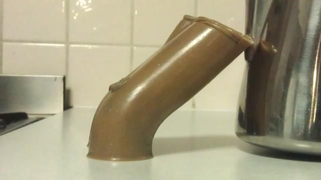
Following is the picture from throath I was talking eariler, it's been finished by using some stone grinder(carbide ... something).
It's even more roguh than 60 grit finish. It may be to enhance the flow, but as it's that rough it may rather be to ensure good fuel atomization. I have similar texture, need to ask from Andre one day.
It also goes to half way of seat. I think atomization is even more important in boosted application as it will provide faster burn process which means less possible knocking, right/wrong?

The fuel atomization is difficult as it needs back_to_back dyno tests to find the results. Needs lot's of work and costs will get too high for customers..
Following is the picture from throath I was talking eariler, it's been finished by using some stone grinder(carbide ... something).
It's even more roguh than 60 grit finish. It may be to enhance the flow, but as it's that rough it may rather be to ensure good fuel atomization. I have similar texture, need to ask from Andre one day.
It also goes to half way of seat. I think atomization is even more important in boosted application as it will provide faster burn process which means less possible knocking, right/wrong?
03-19-2014, 05:23 PM
#216
Rennlist Member
Thread Starter
I have some 60 grit stones I think. I will start on the heads this weekend. Just smoothing and making the surface correct. Nothing more at this time.
03-21-2014, 12:30 PM
#217
Rennlist Member
Thread Starter
I may be removing the guides on this head to put new ones in. I am unsure right now if if it's needed, prudent, or not needed in the context of what I am trying to accomplish in the context of this motor.
I found this to remove them:
http://www.goodson.com/Piloted-Core-...and-7mm-Pilot/
I found this to remove them:
http://www.goodson.com/Piloted-Core-...and-7mm-Pilot/
11-29-2014, 05:45 AM
#218
Rennlist Member
Join Date: Feb 2011
Location: Mostly in my workshop located in Sweden.
Posts: 2,226
Received 442 Likes
on
244 Posts
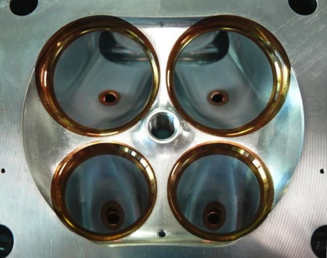
I have started some experimental grinding and flow testing performed on a cut off piece of a cylinder head given to me by Slate Blue. From pictures you can see the difference in valve seat inner diameter after being cut for 39mm intake valves. So far I have managed to increase the intake flow by 23% at .500" lift over a 100 mm bore, from 296 CFM to 364 CFM. The intake valves at present are 39mm. The CSA of the intake port at the flange is unchanged. Later on full race porting with 42mm intake valves will be tested.
�ke
�ke
Last edited by Strosek Ultra; 04-29-2015 at 09:31 AM.
11-29-2014, 03:38 PM
#219
I have started some experimental grinding and flow testing performed on a cut off piece of a cylinder head given to me by Slate Blue. From pictures you can see the difference in valve seat inner diameter after being cut for 39mm intake valves. So far I have managed to increase the intake flow by 23% at .500" lift over a 100 mm bore, from 296 CFM to 364 CFM. The intake valves at present are 39mm. The CSA of the intake port at the flange is unchanged. Later on full race porting with 42mm intake valves will be tested.
�ke
�ke
That head had 41.91 mm valves and was tested on a 103 mm or 4.060" bore. At the time I didn't want to pay for custom valves and we just used my exhaust valves fron another project. Therefore the valves had a big tulip on them which I know is not optimum. I don't know what the flow would have been on a larger bore either.
The following users liked this post:
Darklands (07-24-2021)
12-01-2014, 05:53 PM
#220
Rennlist Member
Thread Starter
great pictures. Thanks for sharing the info.
12-11-2014, 03:30 PM
#221
Rennlist Member
Join Date: Feb 2011
Location: Mostly in my workshop located in Sweden.
Posts: 2,226
Received 442 Likes
on
244 Posts
MILD and WILD PORTING with 39mm INTAKE VALVES.
Here are the flow numbers for several stages of modifications. I do not show all the tests carried out, only the important ones. The flow figures are taken at a lift of 2mm, 4mm, 6mm and so on up to 14mm. The airflow is measured at a depression of 10 inches of water column and the figures are converted to 28 inches of water column to make it easier to compare with other numbers. The large 39mm intake valves need oversize valve seat insert rings which I did not bother to install as this is done for air flow testing only. Nor did I bother to make a nice surface finish as it does not add to the flow. The cross section area at the port flange is unchanged in order to keep the air velocity up. The minimum modifications needed in order to be able to run the oversize 39mm intake valves is a great improvement for a reasonable amount of work contrary to the extended amount of working hours for the maximum modifications. For those interested there is a formula to calculate horsepower from flow for an all out modified engine. The formula is 0.26HP per CFM per cylinder.
For this flow study I have tried most of the tricks in the book. Optimizing of the short side radius and the revised shape of of the valve head did more to the flow than expected.
STOCK INTAKE PORT 2x37mm VALVES. Inside diameter at seat ring 30,8mm. Valve head back angle 20 dgs. Bore 100mm.
69,9 147,4 226,4 276,4 290,7 299,2 299,9
MINIMUM MODIFICATIONS 2x39mm VALVES. The valve seats cut for 39mm valves. Inner diameter at the valve seat ring 34mm. MIRA #4029 valve seat cutter. Smoothing and blending of the bowl/pocket area from the valve seat insert ring down to where the valve guide is coming out of the port roof. Valve head back angle 20 dgs with a rather wide 30 dgs backcut. Lower part of valve stem 6,5mm. Width of valve seat 1,0mm. Bore 100mm.
73,3 160,5 241,1 304,9 337,2 351,2 354,7
MAXIMUM MODIFICATIONS 2x39mm VALVES. Divided ports cut open 3mm wider and 5mm higher at the roof. Valve guide boss streamlined. Divider wall sharpened and streamlined. Cavity for fuel injector filled. Cross section area of intake port at the flange unchanged but the rough surface made somewhat smoother. Bore 100mm.
77,6 162,1 241,1 305,7 347,9 368,0 379,3
SHORT SIDE RADIUS OPTIMIZED STAGE I cut out by 1mm. Bore 100mm.
78,5 162,6 242,3 307,1 353,6 381,6 392,5
SAME as ABOVE but with 104mm bore. Combustion chamber close to the intake valves cut out (unshrouded) to the larger 104mm bore. Not very much metal removed. Cannot explain why the high lift flow became reduced by this modification.
79,3 162,8 242,3 307,1 350,9 375,5 388,5
INTAKE VALVES MODIFIED. Back angle reduced to 10 dgs (nail shaped valve head) with a narrow 30 dgs back cut. Seat width 1,0mm. Smaller head to stem radius (R=7mm). The valve became very lightweight 50 grams compared to 65 grams for the stock intake valve. Bore 104mm.
78,5 167,3 248,4 316,2 355,1 374,8 383,0
SHORT SIDE RADIUS OPTIMIZED STAGE II cut out by 2mm. Bore 104mm.
76,8 165,2 245,2 313,6 356,6 383,1 397,6
PORT ROOF and LONG SIDE WALL OPTIMIZED. Valve guide boss cut away, valve guide cut flat with the port roof. Port cross section area at the flange unchanged about 1700 mm2 (2.635 sqin). Bore 104mm.
77,3 165,2 244,9 313,6 358,1 386,9 402,4
I also tried D-shaped divided intake ports where the radiused floor was raised by about 7mm and made flat but it did not bring anything. Think the optimizing of the short side radius did all the difference.
Two first pictures show the Minimum Modifications.
Valves from left to right: Stock S4 37mm intake. Oversize 39mm semi-tulip. Oversize 39mm flat nail-shaped valve for best flow and low weight - only 50 grams.
Two last pictures show the Maximum Modifications.
�ke
Last edited by Strosek Ultra; 12-11-2014 at 03:51 PM.
12-11-2014, 03:46 PM
#222
Rennlist Member
Join Date: Feb 2011
Location: Mostly in my workshop located in Sweden.
Posts: 2,226
Received 442 Likes
on
244 Posts
First image show the modifications done to the short side radius (Stage II).
Second image may give you the idea how the short side radius has been modified.
Blue line Stage I. At 120 dgs of the valve seat ring inner circumference the radius is cut down by 1mm for a less abrupt turn for the air. For Stage II red line it is 2mm which is the maximum possible.
Third image the flow chart.
�ke
12-12-2014, 12:48 AM
#223
Ake,
Very nice work and great results first of all. I would say that is the highest flowing 928 intake created to date. I would be very interested to see a gel flex mould of that port.
Here is mine, flowing the equivalent of 376 cfm but with bigger valves on a slightly smaller bore i.e 103 mm. Albeit with tulip exhaust valves and that may make a bit of a difference.
It appears you have widened and raised the port just before the guides and it likes this. It likes this much more so than in my port which is more transitional.
Maybe more like this port?
01-14-2015, 12:32 PM
#224
Rennlist Member
Join Date: Feb 2011
Location: Mostly in my workshop located in Sweden.
Posts: 2,226
Received 442 Likes
on
244 Posts
Some of the basic tools I have for the porting of cylinder heads. A high speed (25000 rpm) electric die grinder, carbide rotary files of different sizes and shapes. It is very important to use rotary files having wide flutes designed especially for the cutting of aluminum. For the cutting of the valve seats I have the MIRA valve seat cutting equipment (see post #218). I have had that apparatus for thirty plus years and it has served me well all the time. MIRA do offer numerous form-tools of many different shapes.
http://mira-webshop.webstores.ch/pi/VGX-21-Package.html
http://mira-webshop.webstores.ch/sho...ls_preview.pdf
For the refacing of the valves I have a very old Van Dorn valve grinding machine. It originates from the Swedish Airforce of the days when they worked on the Merlin engine. After being fixed up the valve grinder has been doing its job perfectly ever since I got it in the mid 70�s.
http://www.flightglobal.com/pdfarchi...0-%200241.html
�ke
01-16-2015, 06:30 AM
#225
Rennlist Member
Join Date: Feb 2011
Location: Mostly in my workshop located in Sweden.
Posts: 2,226
Received 442 Likes
on
244 Posts
Flow testing of 928S (Euro) 2-valve cylinder head. Stock head with 45mm valve, modified with oversize 48mm valve and heavily modified with 52mm valve. Compare with the flow graph of the 4-valve head (post #222) and you can see how superior the 4-valve head is regarding the flow.
�ke
�ke
Last edited by Strosek Ultra; 07-23-2015 at 06:19 AM.