
Rear Axle Boot Replacement Complete - here's the pics
 12-19-2007, 01:36 AM
#1
Rennlist Member
Thread Starter
Join Date: Sep 2007
Location: Ridgecrest, California
Posts: 1,363
Likes: 0
Received 143 Likes
on
28 Posts
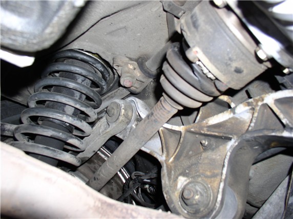
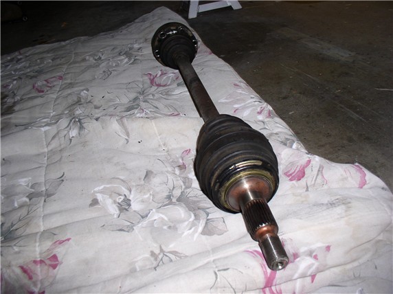
Last weekend, I replaced the CV joint boots on the rear axle and thought I'd share the experience with pics.
I had never done this before so decided to go all the way and take the joints apart and inspect and get a little experience. Besides, I had never actually seen a CV joint before and had to know what was in there!
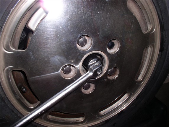
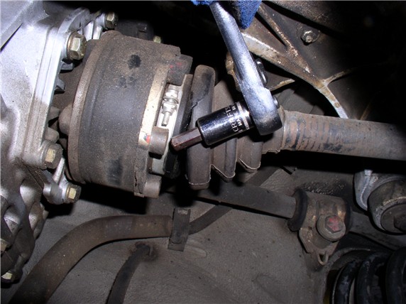
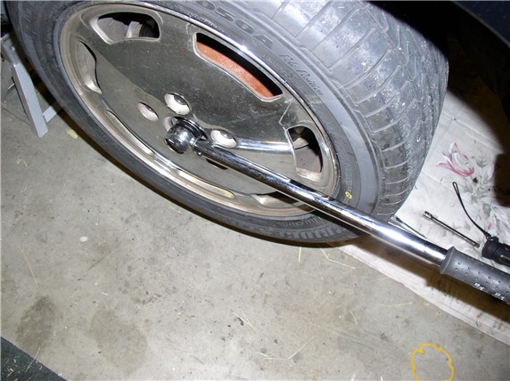
Leave the car on the ground, weight on wheels, and go after the wheel nuts. I applied the parking brake and I used a 1/2" breaker bar and 1 1/4" 6-point socket to loosen. Ended up putting my foot on the handle and applying most of my weight (but not all) and it came loose with no fuss. I went ahead and took the nut and washer off. I would recommend using an impact socket and an extension bar on the breaker bar handle to make it easier. Then jack the car up at the rear for the rest of the job. It was not necessary take the wheels off for the job, so I left them on.
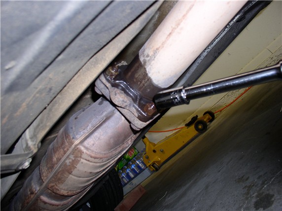
Next, I detached the exhaust at the back of the cat - 13mm nuts. You'll need to counterhold the bolt end. I supported the cat with a floor jack. I used WD-40 on the nuts to ease them off. My brain said, "use a small amount", my finger didn't listen!
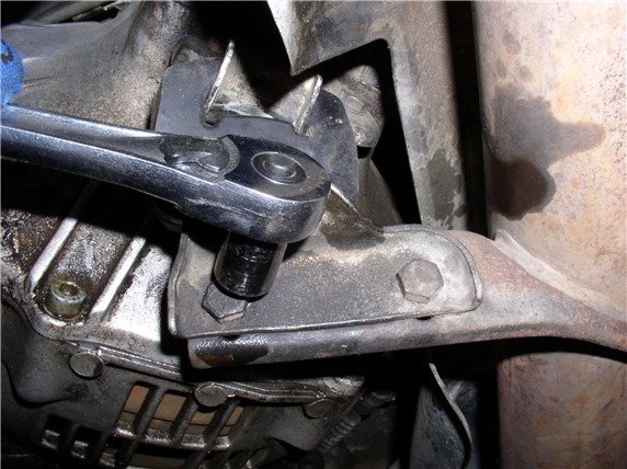
Then came the mid-exhaust hanger - 13mm nuts. Counterhold the bolt end. Simply detached at the bracket bolts.
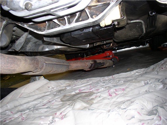
At this point I simply let the exhaust rest on the ground. It allowed enough room to remove the driver side axle.
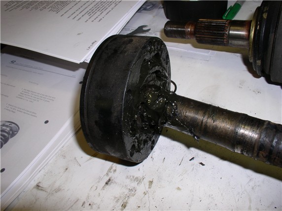
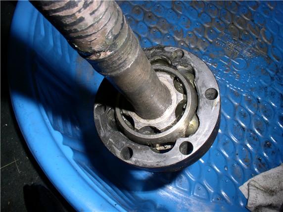
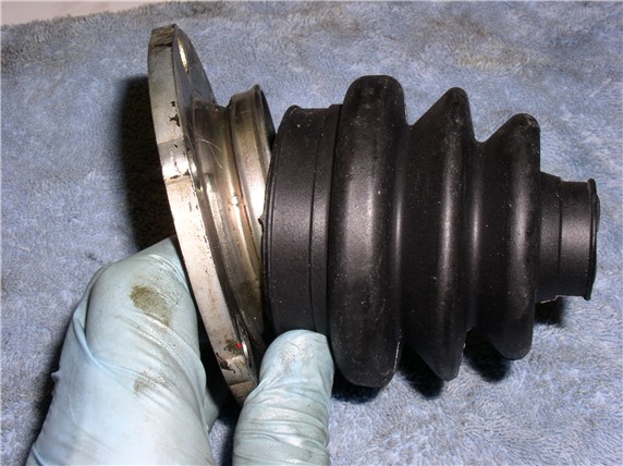
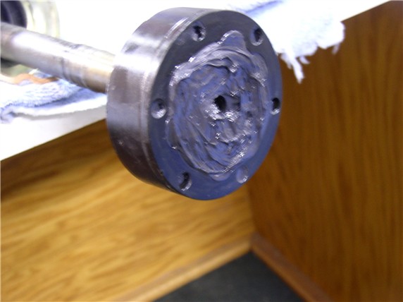
Here's the inner boot that was torn. I could see no signs of lube flung everywhere and in fact it looked like it had been torn for some time. Lube was being flung at the outer boot (same axle) and seemed to be coming from the small end of the boot seal around the axle.
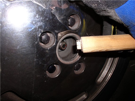
To take off the allen bolts, use an 8mm allen socket. There are six bolts per axle. With the parking brake set, I did 2 at a time on each axle then released the brake and rotated the tires so the next 2 were accessible. Set the brake and loosen. Repeat until all 6 are out. One thing I had to keep in mind was making sure I had good contact with the allen socket in the bolt head. With the boot a little in the way there, and not rotating the tire to get a good position, I could see how easy it would be to get the allen in slightly crooked and strip the bolt out. So be careful and take your time.
Once the bolts were out, I simply rested the axle on the suspension tubes while I went around to the outside of the wheels to push the axle out.
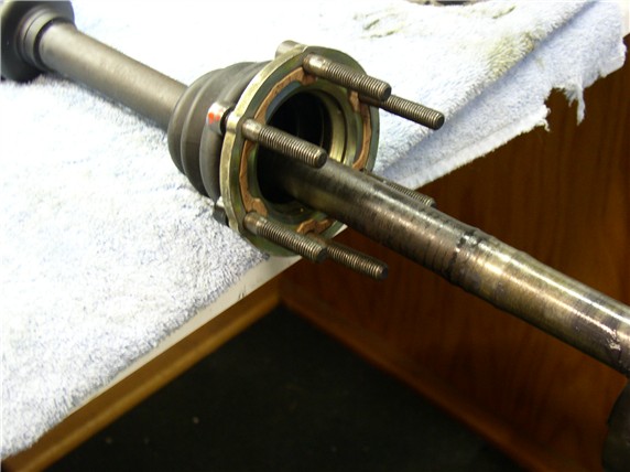
I fashioned a wooden dowell to tap the axle out. Used a wooden closet rod laying around and shaped the end down with a dremel to a dimension slightly smaller than the axle so it would fit into the hub spline and fully push the axle out. A few taps with the hammer and they come right out.
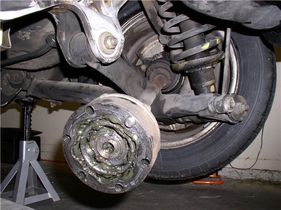
Got back under the car and easily maneuvered the axle out.
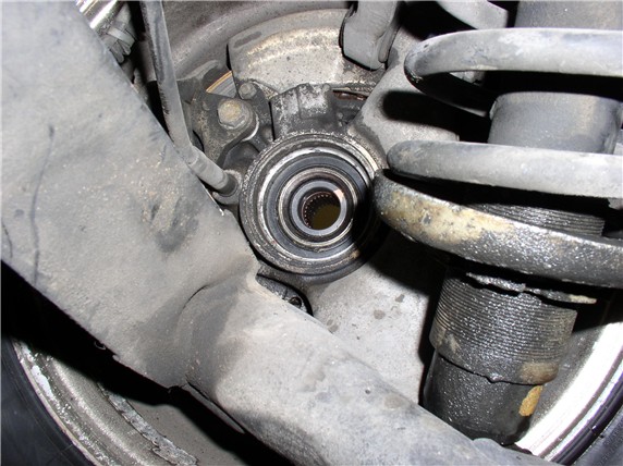
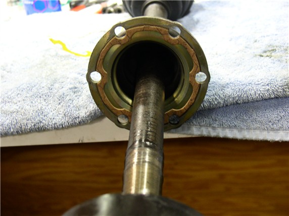
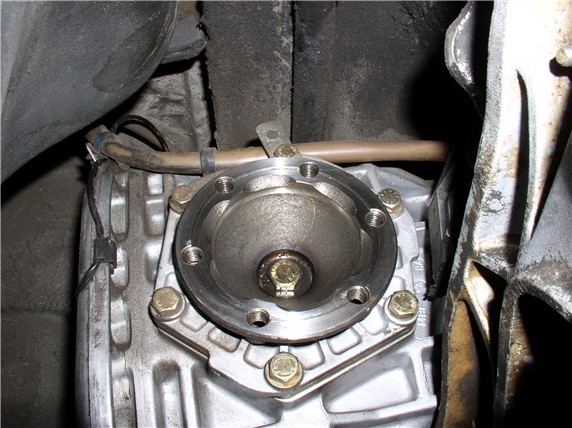
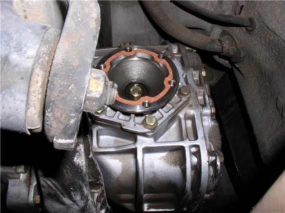
Here's a pic of the inside wheel the axle came out of...
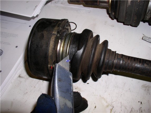
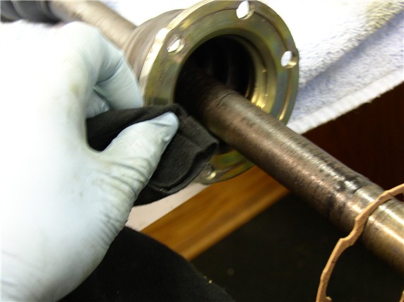
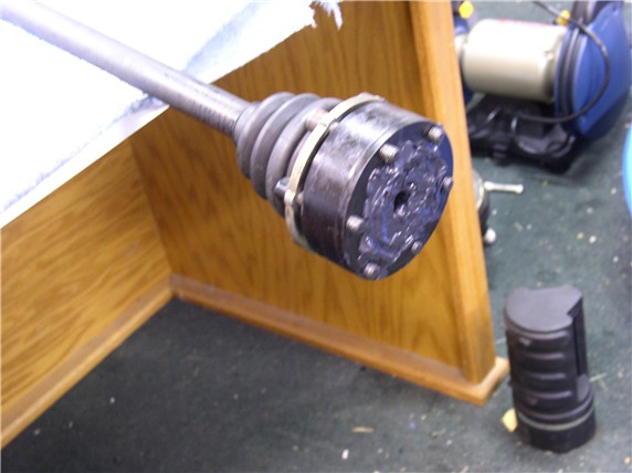
After the axle is out, I put it on the bench and removed the clamps on both inner and outer boots. I then pulled the boot off the flange and simply used a utility knife to cut/saw though the boot carefully.
With the boots off, the joints were ready for an initial cleaning - lots of grease, couldn't see anything.
I wiped a lot of the grease off with a rag first, then I used odorless mineral spirits to clean off most of the grease. To clean the outers (since the joint is welded on), I used mineral spirits in a good spray bottle and sprayed jets into the outer joint. The dissolved grease drained out the bottom of the shaft. Took about 20 minutes to get one outer joint good and clean this way. I went through almost a gallon of mineral spirits.
next post....
I had never done this before so decided to go all the way and take the joints apart and inspect and get a little experience. Besides, I had never actually seen a CV joint before and had to know what was in there!
Leave the car on the ground, weight on wheels, and go after the wheel nuts. I applied the parking brake and I used a 1/2" breaker bar and 1 1/4" 6-point socket to loosen. Ended up putting my foot on the handle and applying most of my weight (but not all) and it came loose with no fuss. I went ahead and took the nut and washer off. I would recommend using an impact socket and an extension bar on the breaker bar handle to make it easier. Then jack the car up at the rear for the rest of the job. It was not necessary take the wheels off for the job, so I left them on.
Next, I detached the exhaust at the back of the cat - 13mm nuts. You'll need to counterhold the bolt end. I supported the cat with a floor jack. I used WD-40 on the nuts to ease them off. My brain said, "use a small amount", my finger didn't listen!
Then came the mid-exhaust hanger - 13mm nuts. Counterhold the bolt end. Simply detached at the bracket bolts.
At this point I simply let the exhaust rest on the ground. It allowed enough room to remove the driver side axle.
Here's the inner boot that was torn. I could see no signs of lube flung everywhere and in fact it looked like it had been torn for some time. Lube was being flung at the outer boot (same axle) and seemed to be coming from the small end of the boot seal around the axle.
To take off the allen bolts, use an 8mm allen socket. There are six bolts per axle. With the parking brake set, I did 2 at a time on each axle then released the brake and rotated the tires so the next 2 were accessible. Set the brake and loosen. Repeat until all 6 are out. One thing I had to keep in mind was making sure I had good contact with the allen socket in the bolt head. With the boot a little in the way there, and not rotating the tire to get a good position, I could see how easy it would be to get the allen in slightly crooked and strip the bolt out. So be careful and take your time.
Once the bolts were out, I simply rested the axle on the suspension tubes while I went around to the outside of the wheels to push the axle out.
I fashioned a wooden dowell to tap the axle out. Used a wooden closet rod laying around and shaped the end down with a dremel to a dimension slightly smaller than the axle so it would fit into the hub spline and fully push the axle out. A few taps with the hammer and they come right out.
Got back under the car and easily maneuvered the axle out.
Here's a pic of the inside wheel the axle came out of...
After the axle is out, I put it on the bench and removed the clamps on both inner and outer boots. I then pulled the boot off the flange and simply used a utility knife to cut/saw though the boot carefully.
With the boots off, the joints were ready for an initial cleaning - lots of grease, couldn't see anything.
I wiped a lot of the grease off with a rag first, then I used odorless mineral spirits to clean off most of the grease. To clean the outers (since the joint is welded on), I used mineral spirits in a good spray bottle and sprayed jets into the outer joint. The dissolved grease drained out the bottom of the shaft. Took about 20 minutes to get one outer joint good and clean this way. I went through almost a gallon of mineral spirits.
next post....
 12-19-2007, 03:02 AM
#2
Rennlist Member
Thread Starter
Join Date: Sep 2007
Location: Ridgecrest, California
Posts: 1,363
Likes: 0
Received 143 Likes
on
28 Posts
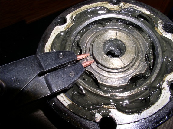
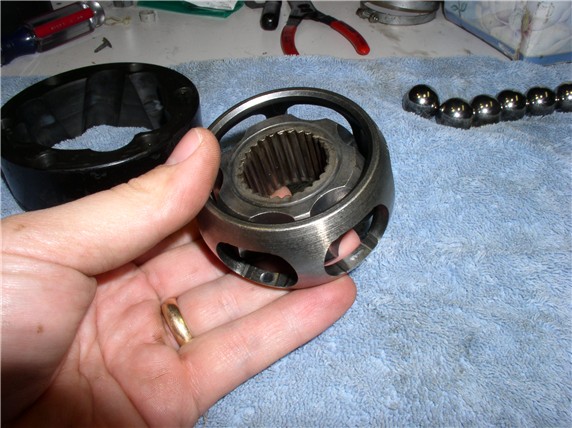
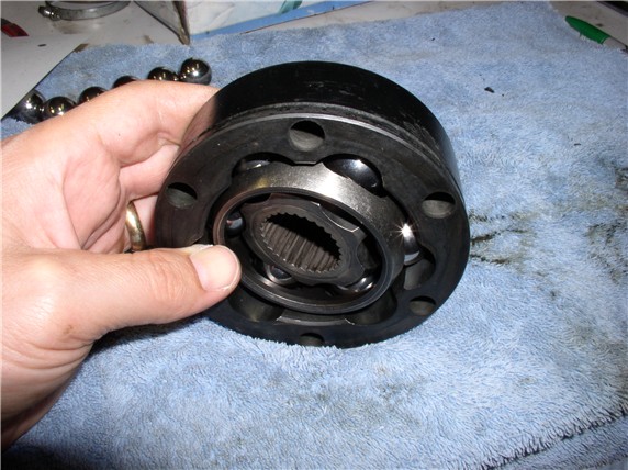
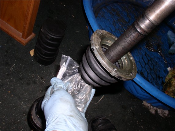
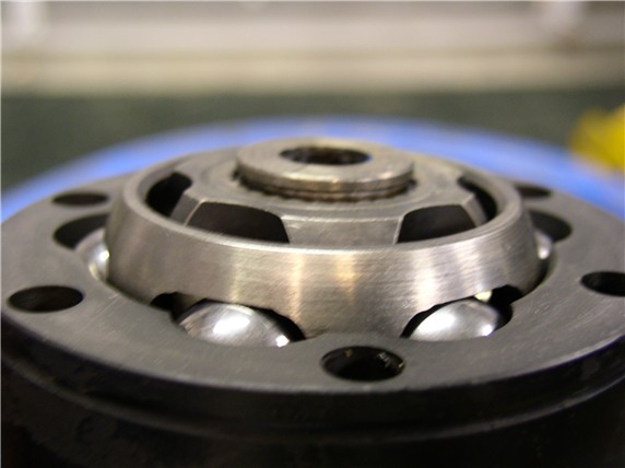
Once the grease is cleaned off enough to see things. I took off the circlip holding the cv joint on the axle. I first used snap ring pliers but it took a bit of work to get one off. So I bought some pliers made for the job and it worked much better. A picture of the correct pliers comes later. I also made note at this point any distinguishing marks to identify which way the bearing hub, cage and outer collar were oriented for reassembly. For example, the outer collar has a groove in the outer surface near the end that mates to the transmission. The bearing hub has a groove in the surface that faces the transmission (see picture - close to circlip). Even the cages had a slight difference in top and bottom edges. Around the rim on the top edge of the cage, the "flat" is narrower than on the bottom rim of the cage - it's a slight difference.
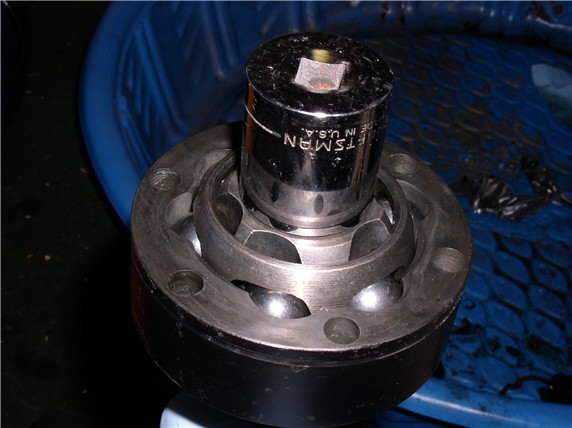
After the circlip is removed, I took the axles to the auto hobby shop to borrow their hydraulic press to press the axle out of the cv joint. On the way to borrow the press, the wrapped axles broke free from the blanket I wrapped them in and before I knew what happened, I began to hear all kinds of metal parts klinking together in the back of my car. The bearings had come out! Not what I planned. The WSM says to keep the cv joints together and not mix them. The bearings belong to a tolerance group. However I could see no distinguishing marks to match the bearings to the cv joint. The rest of the joints I was able to keep together (bearing hub, cage and outer collar). When I got the shop, the axles pressed out of the joint easily. I need to get a press for home -- think I wil take a look at what HF has.
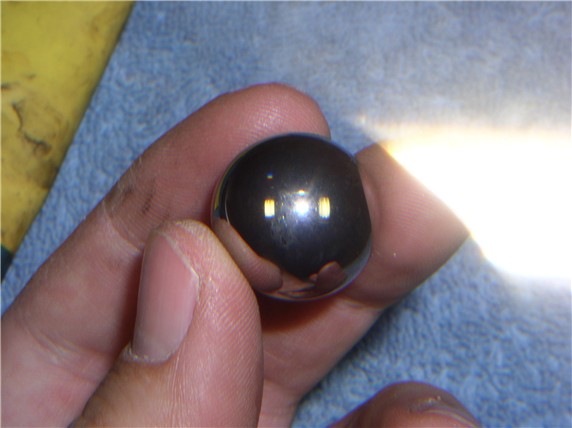
When I got back home, I cleaned each bearing, cage, bearing hub, and outer collar with a rag and inspected them. Of course, I have no idea what looks good or what looks bad. So I posted some pics on rennlist and the opinions were they look fine. Here's one of the bearings:
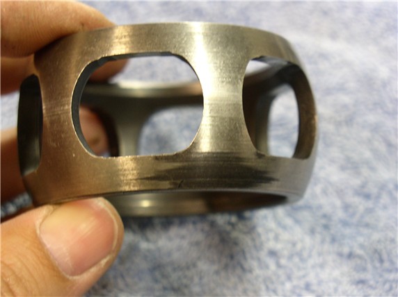
Here's one of the cages. You can see where the bearings contact the cage but the wearing is very light.
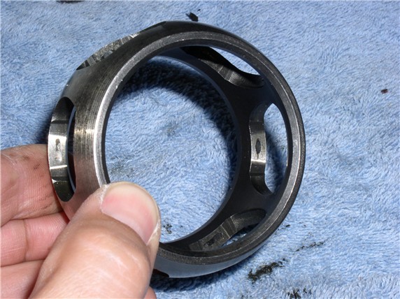
On this cage, there was some imprints on the outside of the cage but not serious enough to warrant replacement.
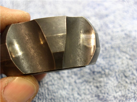
Here's the hub. You can see where the bearing contacts are. Running my finger over the shiny spots, there was imperceptible wear at these places so It was also good to go back in.
I began reassembly of the joint by placing the bearing hub in the cage. I made sure the hub and cage were matched same as when I took them apart (i.e., groove in hub on top, cage top matched). Cage slots can be matched up with any hub bearing slot - makes no difference according to the WSM.
Then place the 6 bearings in (from the outside of the cage). Since all my bearing were mixed up. I picked any 6.
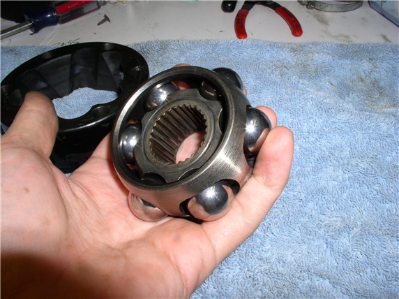
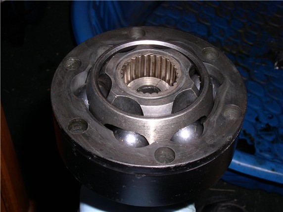
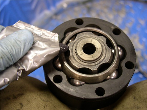
The tricky part is placing the hub/cage/bearings into the outer collar. Notice the groove on the outer surface of the collar - it's near the end that will face the transmission. I slid the assembly into the collar sideways then rotate the bearing assembly around (swing it into the collar). If a bearing falls out, it's can be re-inserted after you get it the rest of it together. The WSM has a picture of this. You have to match the narrow surface areas with the wide surface areas of the collar to get it right. Notice at the 12 o'clock position of the outer coller (where the allen bolt goes). Right below that is the narrow surface of the collar - notice the bearing hub at the same location - its wide. Also, If the joint is locked when you press in the hub assembly, you missed it. That's what I did first time. Then I took it back out, rotated the bearing assembly right one bearing and put it in again and presto! It worked. The inner assembly should move freely.
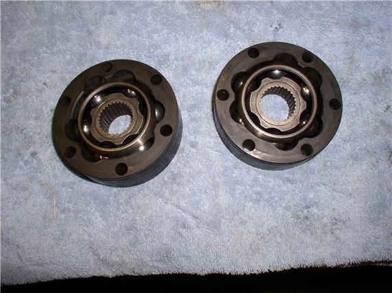
Here's the two joints assembled...notice the wide is matched to narrow on the inner hub and outer collar.
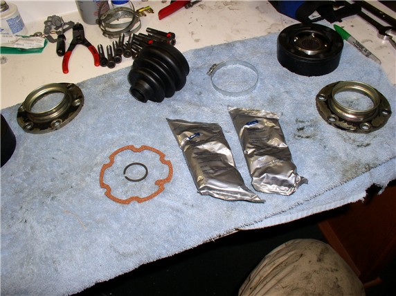
I purchased the boot kit from 928 Intl. One kit came with one boot, one large clamp, one circlip, one gasket/seal and 2 tubes of grease. Both tubes of grease go into one joint.
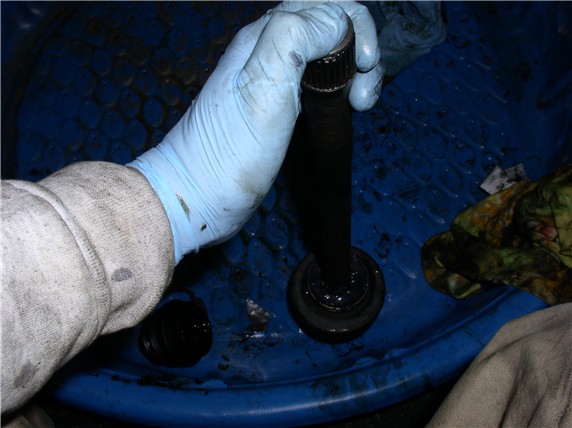
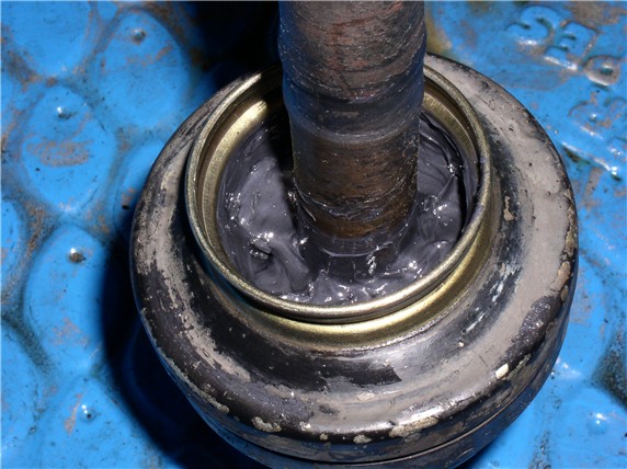
Next it came time to put the 2 tubes of grease in the outer joint first. Hold the axle verticle with the outer joint down near the ground. Press the axle down to create more space to squirt the tubes of grease in until its full. Smear it around so the grease is level with the boot flange.
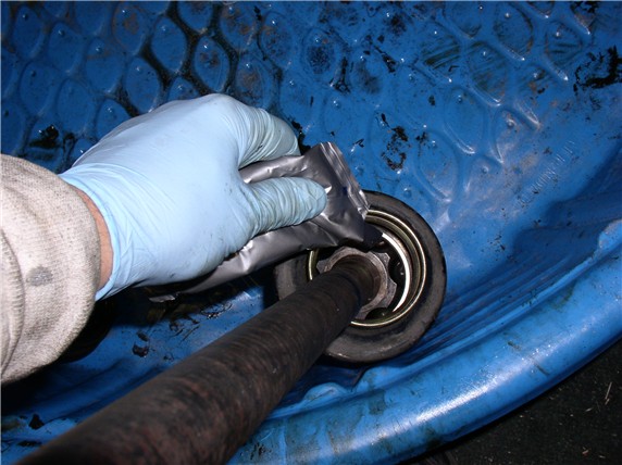
This next trick I learned reading the CV boot replacement tips I found on Nichols (I believe). You suck the grease into the joint. Place one hand on the bottom of the axle shaft and place your finger over the end of the axle to plug the hole. With the other hand at the other end of the axle, place your thumb over the end of the axle to plug the other hole. Then pull on both ends of the axle (in opposite directions). This sucks the grease into the joint. If you've sealed both ends of the axle well, it will be difficult to pull on both ends of the axle. When you've pulled the joint all the way up, remove one of your fingers and push it back down again, plug the holes and pull on the ends of the axle again. Repeat several times and you will see the grease dissapear into the joint. I did this until both packages of gease had been sucked into the joint. Here's a pic -- wish I had a 3rd hand to take the picture!
After the grease is in the outer joint, I cleaned off the excess from around the boot flange.
I'll post the rest tomorrow...have to go now...
After the circlip is removed, I took the axles to the auto hobby shop to borrow their hydraulic press to press the axle out of the cv joint. On the way to borrow the press, the wrapped axles broke free from the blanket I wrapped them in and before I knew what happened, I began to hear all kinds of metal parts klinking together in the back of my car. The bearings had come out! Not what I planned. The WSM says to keep the cv joints together and not mix them. The bearings belong to a tolerance group. However I could see no distinguishing marks to match the bearings to the cv joint. The rest of the joints I was able to keep together (bearing hub, cage and outer collar). When I got the shop, the axles pressed out of the joint easily. I need to get a press for home -- think I wil take a look at what HF has.
When I got back home, I cleaned each bearing, cage, bearing hub, and outer collar with a rag and inspected them. Of course, I have no idea what looks good or what looks bad. So I posted some pics on rennlist and the opinions were they look fine. Here's one of the bearings:
Here's one of the cages. You can see where the bearings contact the cage but the wearing is very light.
On this cage, there was some imprints on the outside of the cage but not serious enough to warrant replacement.
Here's the hub. You can see where the bearing contacts are. Running my finger over the shiny spots, there was imperceptible wear at these places so It was also good to go back in.
I began reassembly of the joint by placing the bearing hub in the cage. I made sure the hub and cage were matched same as when I took them apart (i.e., groove in hub on top, cage top matched). Cage slots can be matched up with any hub bearing slot - makes no difference according to the WSM.
Then place the 6 bearings in (from the outside of the cage). Since all my bearing were mixed up. I picked any 6.
The tricky part is placing the hub/cage/bearings into the outer collar. Notice the groove on the outer surface of the collar - it's near the end that will face the transmission. I slid the assembly into the collar sideways then rotate the bearing assembly around (swing it into the collar). If a bearing falls out, it's can be re-inserted after you get it the rest of it together. The WSM has a picture of this. You have to match the narrow surface areas with the wide surface areas of the collar to get it right. Notice at the 12 o'clock position of the outer coller (where the allen bolt goes). Right below that is the narrow surface of the collar - notice the bearing hub at the same location - its wide. Also, If the joint is locked when you press in the hub assembly, you missed it. That's what I did first time. Then I took it back out, rotated the bearing assembly right one bearing and put it in again and presto! It worked. The inner assembly should move freely.
Here's the two joints assembled...notice the wide is matched to narrow on the inner hub and outer collar.
I purchased the boot kit from 928 Intl. One kit came with one boot, one large clamp, one circlip, one gasket/seal and 2 tubes of grease. Both tubes of grease go into one joint.
Next it came time to put the 2 tubes of grease in the outer joint first. Hold the axle verticle with the outer joint down near the ground. Press the axle down to create more space to squirt the tubes of grease in until its full. Smear it around so the grease is level with the boot flange.
This next trick I learned reading the CV boot replacement tips I found on Nichols (I believe). You suck the grease into the joint. Place one hand on the bottom of the axle shaft and place your finger over the end of the axle to plug the hole. With the other hand at the other end of the axle, place your thumb over the end of the axle to plug the other hole. Then pull on both ends of the axle (in opposite directions). This sucks the grease into the joint. If you've sealed both ends of the axle well, it will be difficult to pull on both ends of the axle. When you've pulled the joint all the way up, remove one of your fingers and push it back down again, plug the holes and pull on the ends of the axle again. Repeat several times and you will see the grease dissapear into the joint. I did this until both packages of gease had been sucked into the joint. Here's a pic -- wish I had a 3rd hand to take the picture!
After the grease is in the outer joint, I cleaned off the excess from around the boot flange.
I'll post the rest tomorrow...have to go now...

 12-19-2007, 08:45 AM
#6
Rennlist Member
Thread Starter
Join Date: Sep 2007
Location: Ridgecrest, California
Posts: 1,363
Likes: 0
Received 143 Likes
on
28 Posts
THANKS! No troubles driving....I just needed to replace the boots because one was cracked and would eventually get contaminated and the joint would fail...eventually. Also another boot was leaking and flinging grease everywhere. I decided to take it all apart mainly to learn how it works.
12-19-2007, 09:40 AM
#7
Rennlist Member
Thread Starter
Join Date: Sep 2007
Location: Ridgecrest, California
Posts: 1,363
Likes: 0
Received 143 Likes
on
28 Posts
OK.....here's some more....
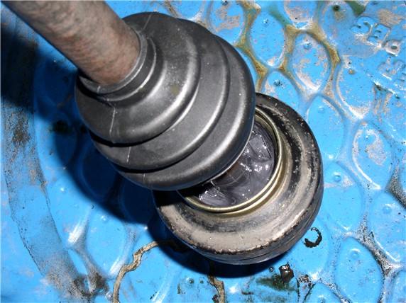
Next I put the boot on the outer joint. I simply slid the boot over the axle end and down the axle. Then pulled the boot over the flange where it locks into place.
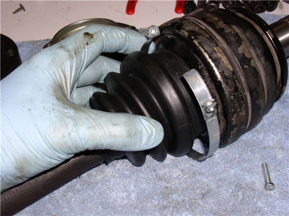
Then put the clamp on....
Next was the inner boot. First attached the large opening of the boot on the flange. This was easier than the outer joint because I could get at the inside of the boot through the flange to help it along.
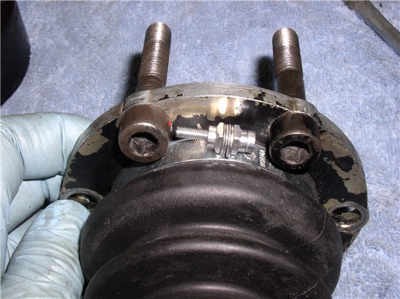
When putting on the clamp, make sure you position the clamp screw between the bolt holes so it doesn't interfere with the bolts.
Next, put the inner boot on the axle. A little more difficult to put on small end first.
When reading through the Nichols CV Boot tips, I ran across a tip that someone used a piece of tin cut down and rolled inside the boot to help get it slid on. This was a great idea! But I couldn't find any tin around, so I used the next best thing that was handy - a Ziplock Baggie! Of course! I rolled the baggie around the axle - Ziplock end toward the outter CV joint (this gives you something to grap onto when pulling the boot on).
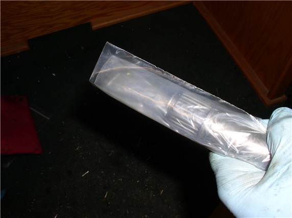
Next, thread the end of the baggie through the small boot hole and push the small end of the boot onto the axle shaft. You don't have to push it on very far, just enough to get it on the very end of the axle.
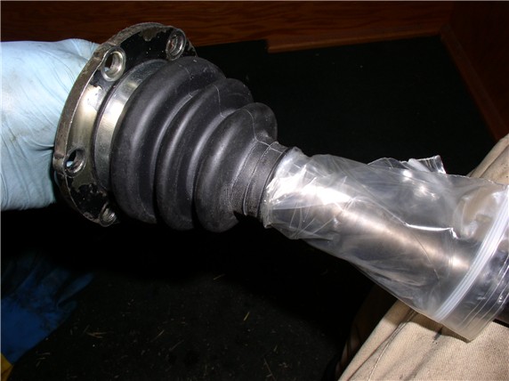
Then push the boot from the top while pulling on the Ziplock end at the bottom and the boot slides over the the axle shaft. Works slicker than snot, literally!
I pulled the boot all the way down the shaft near the outer cv joint out of the way then simply pulled the baggie out. Next, I put the flange gasket on - adhesive side toward the flange but didn't remove the adhease strip yet. I wanted to pack the joint with grease first then (if I didn't make a mess), attached the gasket to the flange.
Next, I installed the inner CV joint onto the axle. I placed the the joint on the shaft and lined up the splines and pressed it on by hand just to get it started. I made sure it was facing the right direction (i.e., the groove on the outer collar near the end that's facing the transmission).
Since I didn't have the hydraulic press, I used the 1 1/4" socket to tap the joint on. Center the socket on the joint then using one hand, hold the axle shaft off the ground and use the other hand to tap the socket to push the joint onto the shaft. I gave it 5 or 6 medium-sized taps and it was on and seated. The mass of the axle and joints provides a good counter force to the hammer blows so it's not difficult to hold onto the shaft while tapping the joint on. I didn't want to tap the joint on while the other end of the axle was on the ground because the outer joint would be absorbing the hammer blows and THAT didn't sound good.
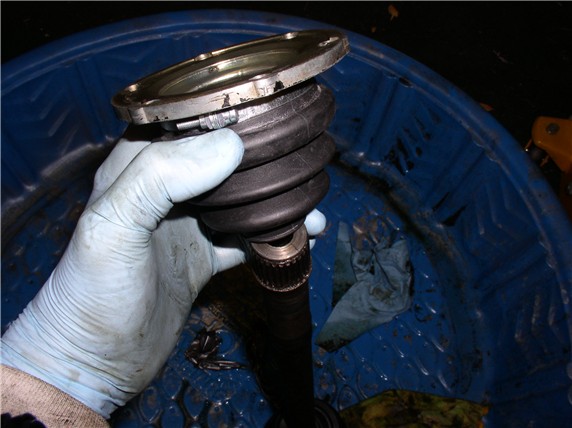
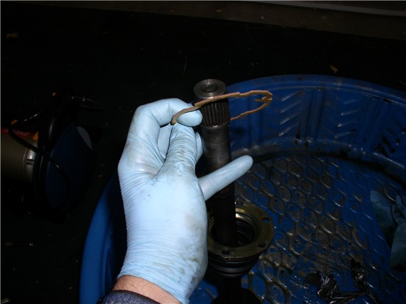
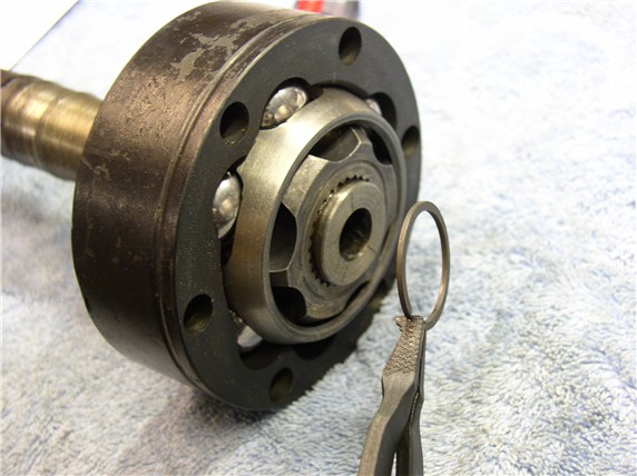
When the joint is fully seated on the axle, the circlip ring slot on the very end of the axle shaft should be visible.
Next, attach the circlip. Here's the pliers I bought to work with these circlips, much better than trying to use the snap ring pliers!
Next post.....
Next I put the boot on the outer joint. I simply slid the boot over the axle end and down the axle. Then pulled the boot over the flange where it locks into place.
Then put the clamp on....
Next was the inner boot. First attached the large opening of the boot on the flange. This was easier than the outer joint because I could get at the inside of the boot through the flange to help it along.
When putting on the clamp, make sure you position the clamp screw between the bolt holes so it doesn't interfere with the bolts.
Next, put the inner boot on the axle. A little more difficult to put on small end first.
When reading through the Nichols CV Boot tips, I ran across a tip that someone used a piece of tin cut down and rolled inside the boot to help get it slid on. This was a great idea! But I couldn't find any tin around, so I used the next best thing that was handy - a Ziplock Baggie! Of course! I rolled the baggie around the axle - Ziplock end toward the outter CV joint (this gives you something to grap onto when pulling the boot on).
Next, thread the end of the baggie through the small boot hole and push the small end of the boot onto the axle shaft. You don't have to push it on very far, just enough to get it on the very end of the axle.
Then push the boot from the top while pulling on the Ziplock end at the bottom and the boot slides over the the axle shaft. Works slicker than snot, literally!
I pulled the boot all the way down the shaft near the outer cv joint out of the way then simply pulled the baggie out. Next, I put the flange gasket on - adhesive side toward the flange but didn't remove the adhease strip yet. I wanted to pack the joint with grease first then (if I didn't make a mess), attached the gasket to the flange.
Next, I installed the inner CV joint onto the axle. I placed the the joint on the shaft and lined up the splines and pressed it on by hand just to get it started. I made sure it was facing the right direction (i.e., the groove on the outer collar near the end that's facing the transmission).
Since I didn't have the hydraulic press, I used the 1 1/4" socket to tap the joint on. Center the socket on the joint then using one hand, hold the axle shaft off the ground and use the other hand to tap the socket to push the joint onto the shaft. I gave it 5 or 6 medium-sized taps and it was on and seated. The mass of the axle and joints provides a good counter force to the hammer blows so it's not difficult to hold onto the shaft while tapping the joint on. I didn't want to tap the joint on while the other end of the axle was on the ground because the outer joint would be absorbing the hammer blows and THAT didn't sound good.
When the joint is fully seated on the axle, the circlip ring slot on the very end of the axle shaft should be visible.
Next, attach the circlip. Here's the pliers I bought to work with these circlips, much better than trying to use the snap ring pliers!
Next post.....
Trending Topics
12-19-2007, 10:02 AM
#8
Rennlist Member
Thread Starter
Join Date: Sep 2007
Location: Ridgecrest, California
Posts: 1,363
Likes: 0
Received 143 Likes
on
28 Posts
Next, I packed the inner joint with grease.
It seemed the best way to pack it in was to press the grease into the nooks and crannies with my finger and rotate the joint at the same time. I couldn't quite get 2 packs of lube in without it producing a mound of grease on each end - ended up using 1 and 3/4 tubes. After packing it in, wipe off the excess grease from the mating surfaces of the CV joint. I used one of the allen bolts to push out any grease that got into the bolt holes - not shown in this picture.
Next, I cleaned the flange surface with brake parts cleaner to get a grease-free seal for the gasket adhesive. I sprayed the brake cleaner on a rag then wiped the surface with the rag. I also did the same to the trasmission side flange before adhering the gasket there.
Attach the gasket...
Then I inserted the bolts before sliding the boot down to the joint so it would be easier to line up the bolt holes in the flange with the holes in the joint.
Then slide the boot down into place so the threads are prodruding out the other side of the joint.
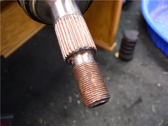
Next, the WSM says to put Optimoly HT, the copper anti-seize, on the axle splines and wheel nut threads.
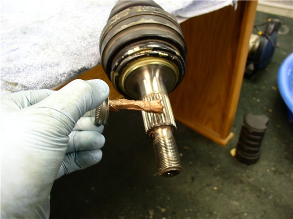
All anti-seized up and ready to go in...
Make sure the flange at the trasmission is grease free before placing the gasket on. I used brake cleaner on a rag and wiped it down.
Then attached the adhesive side of the gasket on the flange.
Next Post...
It seemed the best way to pack it in was to press the grease into the nooks and crannies with my finger and rotate the joint at the same time. I couldn't quite get 2 packs of lube in without it producing a mound of grease on each end - ended up using 1 and 3/4 tubes. After packing it in, wipe off the excess grease from the mating surfaces of the CV joint. I used one of the allen bolts to push out any grease that got into the bolt holes - not shown in this picture.
Next, I cleaned the flange surface with brake parts cleaner to get a grease-free seal for the gasket adhesive. I sprayed the brake cleaner on a rag then wiped the surface with the rag. I also did the same to the trasmission side flange before adhering the gasket there.
Attach the gasket...
Then I inserted the bolts before sliding the boot down to the joint so it would be easier to line up the bolt holes in the flange with the holes in the joint.
Then slide the boot down into place so the threads are prodruding out the other side of the joint.
Next, the WSM says to put Optimoly HT, the copper anti-seize, on the axle splines and wheel nut threads.
All anti-seized up and ready to go in...
Make sure the flange at the trasmission is grease free before placing the gasket on. I used brake cleaner on a rag and wiped it down.
Then attached the adhesive side of the gasket on the flange.
Next Post...
12-19-2007, 10:22 AM
#9
Rennlist Member
Thread Starter
Join Date: Sep 2007
Location: Ridgecrest, California
Posts: 1,363
Likes: 0
Received 143 Likes
on
28 Posts
Final stage...
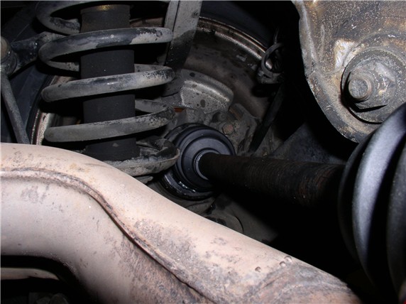
Next, came putting the outer end of the axle back into the wheel. Simply maneuver the axle into place and guide the splined end into the hub splines with your fingers. When the splines were lined up, it slide right in - no force required.
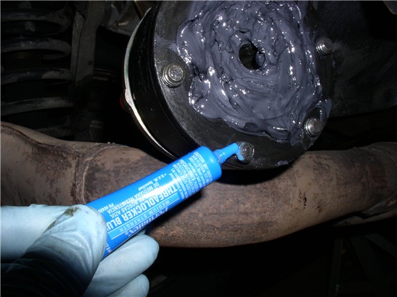
Then I put blue thread locker on the allen bolt threads before putting them back in.
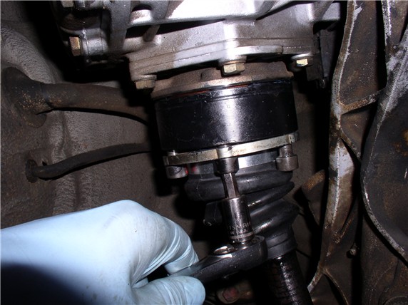
Next, place the inner joint up near the transmission and line up the bolts with the holes. To line them on the first axle, you can turn the flange on the trasmission to line things up. For the second axle, it won't be that easy. So I made sure the parking brake was off and I could turn the wheel to line up the bolt holes with the transmission flange. Once I got a couple of the "accessible" allen bolts started, I simply snugged them down but didn't torque them yet. I rotated the assembly around to get access to the allen bolts - snugging all the bolts down. Then I set the parking brake and torqued 2 bolts at a time - making sure the allen socket was fully seated in the bolt head. Torqued to 60ftlb.
Lastly, I put the wheel nut and washer back on and torqued them down as well. Unfortunately, my torque wrench only goes up to 250ftlb and I needed about 322. So I tightened them down to 250ftlb and I'll drive to a local shop that has a larger torque wrench and tighten down the rest of the way.
The rest of the job is to put the exhaust back in place, set the car back on the ground, done. Ours is still on the jack stands because I'm also repairing trasmission fluid leaks while the car is in the air. Replacing the pan gasket, resevoir o-ring, and intake and return hoses.
THANKS for reading! Feel free to add comments on other/better methods - I'm always looking for better/easier ways of doing things.
Next, came putting the outer end of the axle back into the wheel. Simply maneuver the axle into place and guide the splined end into the hub splines with your fingers. When the splines were lined up, it slide right in - no force required.
Then I put blue thread locker on the allen bolt threads before putting them back in.
Next, place the inner joint up near the transmission and line up the bolts with the holes. To line them on the first axle, you can turn the flange on the trasmission to line things up. For the second axle, it won't be that easy. So I made sure the parking brake was off and I could turn the wheel to line up the bolt holes with the transmission flange. Once I got a couple of the "accessible" allen bolts started, I simply snugged them down but didn't torque them yet. I rotated the assembly around to get access to the allen bolts - snugging all the bolts down. Then I set the parking brake and torqued 2 bolts at a time - making sure the allen socket was fully seated in the bolt head. Torqued to 60ftlb.
Lastly, I put the wheel nut and washer back on and torqued them down as well. Unfortunately, my torque wrench only goes up to 250ftlb and I needed about 322. So I tightened them down to 250ftlb and I'll drive to a local shop that has a larger torque wrench and tighten down the rest of the way.
The rest of the job is to put the exhaust back in place, set the car back on the ground, done. Ours is still on the jack stands because I'm also repairing trasmission fluid leaks while the car is in the air. Replacing the pan gasket, resevoir o-ring, and intake and return hoses.
THANKS for reading! Feel free to add comments on other/better methods - I'm always looking for better/easier ways of doing things.
Last edited by Dwayne; 12-20-2007 at 11:31 AM. Reason: Wheel nut torque spec is 322ftlb not 340.
 I've already put it in my keeper's folder for when I have to do this.
 12-19-2007, 11:48 AM
#11
Archive Gatekeeper
Rennlist Member
Rennlist Member
[clap][clap][clap][clap][clap][clap][clap][clap][clap][clap][clap][clap][clap][clap]
Nice work, Dwayne! Great writeup! One question - where'd you source the knurled tip pliers for the C-clips? I haven't seen those before.
Nice work, Dwayne! Great writeup! One question - where'd you source the knurled tip pliers for the C-clips? I haven't seen those before.
 12-19-2007, 11:51 AM
#12
Rennlist Member
Excellent work Dwayne; may I suggest you create your own web site so this and your other 928 projects are captured for prosperity.
Your camera must be of the grease proof variety
Your camera must be of the grease proof variety
12-19-2007, 12:20 PM
#13
Chronic Tool Dropper
Lifetime Rennlist
Member
Lifetime Rennlist
Member

They are typical to transmission service, among other duties, where a C-shaped lock ring is used to hold gear stacks together on a shaft. Bettr tool houses sell similar parts. I think I have a (ancient...) K-D pair.
For the ring on the end of the half-shaft, you can use a small screwdriver to move the ring a little in the groove before you attack it with the more-typical pliers, the ones with the tips that fit in the holes on the ends of the rings. Once the ring has been rotated a little and "unstuck" in the groove, they generally come out a lot easier.
Dwayne--
Great write-up!! I suspect that a lot more care went into your project than ever went to the initial assembly.
12-19-2007, 03:30 PM
#14
Race Director
Great work.....write up too....It sucks that the OB axles aren't sealed on the inside like the later models
Mental note to self.......Dwayne is a WAY better wrench than me!!
Mental note to self.......Dwayne is a WAY better wrench than me!!
12-19-2007, 03:35 PM
#15
Under the Lift
Lifetime Rennlist
Member
Lifetime Rennlist
Member
Also, my garage and I were complete mess after this job. You could perform surgery with your degree of clenliness.