
Interior LED Changeover (uhm...Looooong)
 01-26-2012, 06:00 PM
#76
Racer
Join Date: Oct 2006
Location: Nashville///'84 944NA, Virtual Luftwaffe pilot, Fighter Ace online
Posts: 250
Likes: 0
Received 0 Likes
on
0 Posts
As far as I can tell the only difference is that the later cars have backlit gauges, as opposed to lighting from in front of the gauges like our early cars.
All this stuff should work, except for that.
Funny you should ask, because...
I was monkeying with this very issue last night. Because early gauges are front-lit (as opposed to backlit like the later 928's)I used an edge-lit white led strip (sold by Alpena at Auto Zone) mounted on the bottom of the gauge panel recess, in front of the gauges. I expected to have an issue with reflectivity off the clear plastic in front of the gauges, but it hasn't happened. I still need to finish the install with a trim piece to prevent stray light and cover the wire end, but the effect is very dramatic, and quite visible, even on bright days, and because I routed power to the strip from the incandescent lighting on the center console, I can still use the dimmer as needed. I actually left the lighting in the pod in place, because the LED strip is so much brighter, on all but the dimmest settings, they are completely washed out anyway. I'll post a pic as soon as I find my camera (again!).
As you can see, the effect is similar to footlighting a stage. At the brightest setting, the master caution light is still clearly visible. I've included a pic of the dimmest setting just before the LED goes out altogether, at which point the incandescents are (just barely) visible again.
I plan on replacing the rest of the bulbs in the panel and the console with LED, but this will at least enable me to see my gauges clearly at night in brightly lighted streets or on sunny days.
Last edited by Vonov; 01-26-2012 at 06:27 PM.
 01-31-2012, 03:13 PM
#77
Rennlist Member
I wrapped up my LED conversion today and thought I�d post a couple pictures to help anyone who does this in the future.
I took the advice and installed an LED in the fan **** of the climate controller rather than running fiber optic to it. Like Ed used to light his fiber optic, I used the same size LED (5 mm, 15� discrete LED) in the **** and simply drilled a hole in the **** as close to the center of the shaft. I also drilled a hole at the 8 o�clock position in the area behind the **** routed the wires out the back. To tone down the brightness of the LED, I inserted a 2.2K ohm resistor.
You�ll notice in Ed�s pictures he used silver paint in the cavity area where the main LED/bulb is (the area between the upper and lower sliders) to increase reflection of the light. I followed his lead but instead used 3M reflective tape and applied it to the top, bottom and rear of the cavity.
The A/C button was easy; the button pulls right out and then so does the bulb. You have a 50/50 chance of getting the polarity right the first time you insert the LED Also no issues replacing the cigarette lighter backlighting; BUT, my bulb on the GTS was different than Ed�s�mine was a BA7s LED, the same as the A/C button.
Unless you have hands the size of a munchkin, you probably won�t be able to remove the side panel of the center console and reach back behind the clock to install the LED�there�s just not enough room. And considering the cost of a new clock, I didn�t want to risk cracking the face of it trying to pop it out of its holder. So instead, I removed the front trim and then had easy access. I posted a couple pictures below to help anyone who�s never gone in there�
I couldn�t be happier with the results. Despite the appearance in the picture, it doesn�t have the �glow� when viewed with the naked eye. People have described it as more vivid, not brighter. I�d agree. If I ever go into the climate controller again, I think I�ll capitalize on Ed�s idea and install another LED in the unit and dedicate it to only brighten the slider *****. No doubt, it would make them much brighter. I also think it would take very little effort to replace the plexiglass that has the fan control speeds (low, high, etc.) and mount a dedicated LED or two in there as well. But at some point, it�s probably overkill�
Thanks again Ed, Keith, Chuck and others here on Renlist. Couldn�t have done this project without you! And I�ll say it again, Ed, your guide is excellent!
Here's the pictures of the climate controller:
I took the advice and installed an LED in the fan **** of the climate controller rather than running fiber optic to it. Like Ed used to light his fiber optic, I used the same size LED (5 mm, 15� discrete LED) in the **** and simply drilled a hole in the **** as close to the center of the shaft. I also drilled a hole at the 8 o�clock position in the area behind the **** routed the wires out the back. To tone down the brightness of the LED, I inserted a 2.2K ohm resistor.
You�ll notice in Ed�s pictures he used silver paint in the cavity area where the main LED/bulb is (the area between the upper and lower sliders) to increase reflection of the light. I followed his lead but instead used 3M reflective tape and applied it to the top, bottom and rear of the cavity.
The A/C button was easy; the button pulls right out and then so does the bulb. You have a 50/50 chance of getting the polarity right the first time you insert the LED
Also no issues replacing the cigarette lighter backlighting; BUT, my bulb on the GTS was different than Ed�s�mine was a BA7s LED, the same as the A/C button.Unless you have hands the size of a munchkin, you probably won�t be able to remove the side panel of the center console and reach back behind the clock to install the LED�there�s just not enough room. And considering the cost of a new clock, I didn�t want to risk cracking the face of it trying to pop it out of its holder. So instead, I removed the front trim and then had easy access. I posted a couple pictures below to help anyone who�s never gone in there�
I couldn�t be happier with the results. Despite the appearance in the picture, it doesn�t have the �glow� when viewed with the naked eye. People have described it as more vivid, not brighter. I�d agree. If I ever go into the climate controller again, I think I�ll capitalize on Ed�s idea and install another LED in the unit and dedicate it to only brighten the slider *****. No doubt, it would make them much brighter. I also think it would take very little effort to replace the plexiglass that has the fan control speeds (low, high, etc.) and mount a dedicated LED or two in there as well. But at some point, it�s probably overkill�
Thanks again Ed, Keith, Chuck and others here on Renlist. Couldn�t have done this project without you! And I�ll say it again, Ed, your guide is excellent!
Here's the pictures of the climate controller:
Last edited by NoVector; 09-09-2018 at 12:49 AM.
01-31-2012, 06:40 PM
#79
Addict
Rennlist Member
Rennlist Member

Unless you have hands the size of a munchkin, you probably won�t be able to remove the side panel of the center console and reach back behind the clock to install the LED�there�s just not enough room. And considering the cost of a new clock, I didn't want to risk cracking the face of it trying to pop it out of its holder. So instead, I removed the front trim and then had easy access. I posted a couple pictures below to help anyone who�s never gone in there�
FWIW, I actually did manage to swap bulbs on the clock without removing the clock. It is darn tight in there (and I don't exactly have small hands), but I found that you can actually use a six-point socket (I'll have to consult my notes to see what size) to remove and reinsert the bulb assembly. Not super easy and requires patience (IIRC, I think I was using the socket without a driver, turning it with one hand on each side), but it worked for me.
02-01-2012, 05:04 PM
#81
Addict
Rennlist Member
Rennlist Member
Thread Starter
Nice job!
It really isn't difficult to go overboard with some of these things, especially now with all the LED types of lighting available. Who can really see those numbers on the rotary dial? Why not just lose that dang thing and install 3 pin head LED's and lose the plastic Hi/LO plate around the know. Make a black panel and install 3 LED's that light up in succession as you twist the fan ****. (all three lit when on HI). Or, use 3 colored LED's that will just reflect into one little window. As you twist the ****, the window changes color. Heck, install pin head LED's in the slider heads and lose that whole fiber optic nightmare.
...or not

 04-03-2012, 04:07 PM
#84
Instructor
Join Date: Oct 2011
Posts: 130
Likes: 0
Received 0 Likes
on
0 Posts
Ok, I'm pretty far along in the planning stages of doing most of the updates detailed in Ed Scherer's PDF, but I have a few questions for whoever cares to take a stab at them. I'm only planning on upgrading the main instrument cluster and the pod switches. If things go well, maybe I'll tackle the center console and other areas later.
#1) I have a 1987 S4, so obviously there are some differences in the document based on Ed's 1990, but has anyone tried this on a 1987? Do the bulbs from Super Bright LEDs more or less work and fit as they did in the 1990? Obviously the number of bulbs will be different. Since the board is definitely different, I was wondering if the holes would still need to be beveled. I have the instrument cluster all apart already (I was trying to improve the lighting reflectors and also tweak the fuel gauge which was only going to 3/4 full).
#2) Since the board is obviously completely different, the figure that shows the polarity markings won't do me any good. What is the best way to figure this out on my board? Is it as simple as putting a bulb in there and just testing it with the positive and negative power on the copper base surrounding the bulb hole? And if it works, then I know. If it doesn't reverse and it should work? Will I risk damaging anything by doing this? This sounded like the best method from what the document said, but I wanted to make sure I wasn't reading things correctly.
#3) For the pod switches (the 5 main cylinder switches on the right and left of the main cluster), I assume those are more or less the same in the 1990 and 1987. But the wire colors in mine do not match the images of Ed's 1990. So for adding the resistors, I don't have any blue wires. I believe I have 2 browns, a white and a brown/blue. At least for the main lights. Then others have more wires. Does anyone know what the correct wire to add the resistors is? And if not, how I can figure this out?
#4) For the dimmer switch, any one have any additional details on how to put this together? Or any updates on how Ed's is working out?
I think that is it for now. I know I've been thinking of questions for this post for a while. This upgrade seemed pretty intimidating for quite a while, but now that I've got everything removed and read and re-read the main post threads on reenlist and Ed's PDF several times over and over again, it doesn't seem quite so bad. Any help or advice is greatly appreciated.
-Bill
04-03-2012, 04:58 PM
#85
Addict
Rennlist Member
Rennlist Member
Ok, I'm pretty far along in the planning stages of doing most of the updates detailed in Ed Scherer's PDF, but I have a few questions for whoever cares to take a stab at them. I'm only planning on upgrading the main instrument cluster and the pod switches. If things go well, maybe I'll tackle the center console and other areas later.
#1) I have a 1987 S4, so obviously there are some differences in the document based on Ed's 1990, but has anyone tried this on a 1987? Do the bulbs from Super Bright LEDs more or less work and fit as they did in the 1990? Obviously the number of bulbs will be different. Since the board is definitely different, I was wondering if the holes would still need to be beveled. I have the instrument cluster all apart already (I was trying to improve the lighting reflectors and also tweak the fuel gauge which was only going to 3/4 full).
Unfortunately, I don't have a pre-'89 to experiment with and have little knowledge of the instrument clusters on them.
I'd be happy to add pre-'89 information to the document if and when somebody completes a conversion successfully and provides me with the detailed information I'd need.
#2) Since the board is obviously completely different, the figure that shows the polarity markings won't do me any good. What is the best way to figure this out on my board? Is it as simple as putting a bulb in there and just testing it with the positive and negative power on the copper base surrounding the bulb hole? And if it works, then I know. If it doesn't reverse and it should work? Will I risk damaging anything by doing this? This sounded like the best method from what the document said, but I wanted to make sure I wasn't reading things correctly.
I didn't realize the boards in the clusters were so different; I've never seen one of the pre-'89-style boards.
If you could take a high-res photo of the front and back of the PC board in question and share those with me, I could try to figure it out.
Many times, you can determine the polarity by inspecting the traces on the printed circuit board. Usually (but not always) lighting circuits like this that predate LEDs will use a common ground, i.e., you'll see that a bunch of lamp circuits have one side of the lamp connected to the exact same trace; only the other side is routed to other separate circuitry (switches, electronics, etc.) I believe on the '89 and later boards like mine, there were only one or two exceptions where my initial guesses were incorrect.
You should also be able to power up your cluster on the bench (I believe that's been done by others like Borland here on Rennlist), but I've never done it myself. That might make it possible to test out your "best guesses" without actually having to reinstall the cluster. If you want to pursue that possibility, I could probably help you do it (I'd hunt down the information about where to connect power to the edge connectors, etc.)
Note that for the twist-lock bulbs and other bulbs that have built-in resistors and diodes, they're reverse polarity protected, so it at least won't do any damage if you get the polarity wrong. But... if you're using discrete (component) LEDs with a current-limiting resistor and you don't also use a separate diode to protect the LED against reverse polarity, you can burn up your discrete LED if you get the polarity wrong.
I wish I had a pre '89 car available for awhile so I could make that guide more complete. Sorry it's not a complete guide for your application.
#3) For the pod switches (the 5 main cylinder switches on the right and left of the main cluster), I assume those are more or less the same in the 1990 and 1987. But the wire colors in mine do not match the images of Ed's 1990. So for adding the resistors, I don't have any blue wires. I believe I have 2 browns, a white and a brown/blue. At least for the main lights. Then others have more wires. Does anyone know what the correct wire to add the resistors is? And if not, how I can figure this out?
I've got a final version (newer and much more bullet-proof than the one installed on my car) of the dimmer module designed and running on a breadboard. The newest design will survive all sorts of nastiness (reversed power, shorted output, etc.) It's also using a more compact, inexpensive microcontroller now (ATtiny85) than my earlier versions.Where the dimmer module stands now: I just need to create some PC boards and get the modules assembled. I keep thinking it's just a couple of weeks away, but I'm constantly getting involved in other projects. I'll try my best to get back to this and get it done.
I think that is it for now. I know I've been thinking of questions for this post for a while. This upgrade seemed pretty intimidating for quite a while, but now that I've got everything removed and read and re-read the main post threads on reenlist and Ed's PDF several times over and over again, it doesn't seem quite so bad. Any help or advice is greatly appreciated.
-Bill
-Bill
Note that the dimmer module can be added later when it's available. Until then, your existing dimmer control just won't do much to dim your LEDs.
Last edited by Ed Scherer; 04-03-2012 at 06:04 PM.
04-03-2012, 05:40 PM
#87
Rennlist Member
Bill -
Sorry I can't help with your 87.
The center console is easy--we just made it hard(er) by trying to light up the blower ****. If you skipped that, you'll find it's much easier than the cluster and pod switches. But like you, I wanted to do everything in stages.
Once you're addicted to LED conversion, check out this thread, specifically Ed's #40 post. He includes the rest of the body lights.
https://rennlist.com/forums/928-foru...ich-one-3.html
FWIW - I've seen in some of Rob Budd's posts that he has an off-the-shelf dimmer that he's really happy with. He mentions it in this thread, but when I go to the company's URL, their website is out of date.
https://rennlist.com/forums/928-foru...ent-bulbs.html
04-03-2012, 05:59 PM
#88
Instructor
Join Date: Oct 2011
Posts: 130
Likes: 0
Received 0 Likes
on
0 Posts
Yeah, I just tackled the instrument cluster first because I already had everything ripped open because I was trying to fix my fuel gauge and boost the light my instrument reflectors were putting out. Glad to hear about the center console. That one sounded the hardest to me.
I wonder if the dimmer Rob Budd mentions is something like the third on this page:
http://www.theledlight.com/dimmers.html
Thanks, Ed. I'll try to take photos as I go and pass on info on the 1987. I work at an engineering college but have been trying to not bother anyone too much with this. Worst case, could I hook up the cluster and start the car and see if the lights work that way? Then note which ones don't and then pull it back out and reverse the ones that don't? I don't think all the cluster lights go off at startup (I can't remember), but maybe that would be an option. And I'm thinking this just for the twist bulbs, not the pod bulbs. But maybe I should just wait the next few days until I get my bulbs in the mail and my questions will make more sense.
I'll post 2 images that I took of the back of the cluster. They aren't great, but I used them to map what bulbs worked of my current incandescent lights (all of them did!) and what color and type of indicator they were so I could order my best guess LEDs.
04-03-2012, 06:24 PM
#89
Addict
Rennlist Member
Rennlist Member
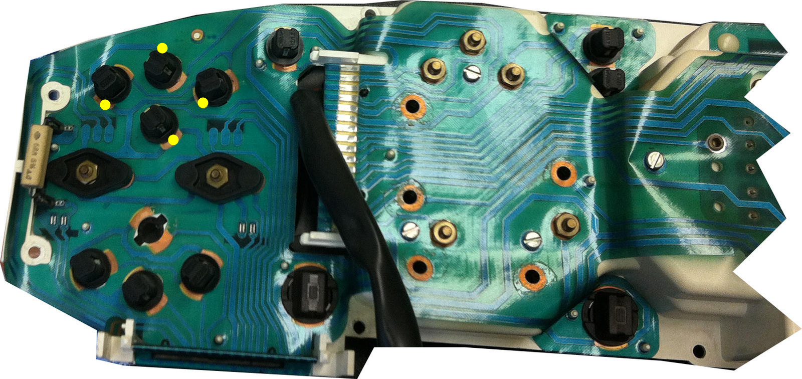
As an example of what I was talking about with looking for traces common to multiple bulbs, the yellow dots indicate some common traces. These are probably where you'd have the cathode (low/ground) side of LED bulbs. If that doesn't work, then they're all the anode (high/12V) side. IOW, the yellow dots mark either all cathode side (more likely) or all anode side (less likely) for the LED bulbs.
04-27-2012, 12:40 AM
#90
Three Wheelin'
Join Date: Mar 2010
Location: Colorado Springs, CO USA
Posts: 1,307
Likes: 0
Received 3 Likes
on
3 Posts
I just did some of this for my instrument cluster. I was planning to swap the backlights and the LCD lamps.
One thing I can tell you (although it may be elsewhere in this thread already) is that the smaller lamps in the digital dash are the B8.4D style. Superbright carries these, so you don't need to do any soldering or other customization to install these twist-lock lamps.
Anyway, two special things about my experience:
1. I also used the WLED-x5 lamps for the backlights. In order to allow these to fit through the stock holes, I had to grind down the side LEDs a bit with a drum sander on a Dremel. No harm from the sanding, though... if anything, it provides a bit of an improvement in lateral dispersion. I also found that I had to push the leads all the way to the outside, at the bottoms of the lamps, in order to get them to make contact with the contacts in the holders.
2. I bought green and red lamps for the LCD display. In the end, though, I decided to stick with the stock incandescents, as the LEDs (the cheaper/dimmer B8.4D's) while being a good brightness, still made for too much of a spotlit (i.e. uneven) backlighting of the LCD panels.
Cheers,
Paul

