
Interior LED Changeover (uhm...Looooong)
 09-07-2011, 08:01 PM
#61

Ed, thanks for that. We've had some not so good luck with some of the kits that are available.
 09-07-2011, 10:22 PM
#62
Three Wheelin'
finally!, I know you didn't ask me, but I've got an early draft of what will ultimately be a rather comprehensive guide to upgrading interior lighting to use LEDs. The section entitled "Parts Summary" near the end with recommended bulbs is complete, so feel free to make use of it.
Converting Porsche 928 Interior Lighting to LEDs
Major thanks to Keith�and a couple of other people I mention in the document�for the trailblazing work they did in this area.
Converting Porsche 928 Interior Lighting to LEDs
Major thanks to Keith�and a couple of other people I mention in the document�for the trailblazing work they did in this area.
 09-08-2011, 10:28 AM
#64
Rennlist Member
Join Date: Jul 2002
Location: Deep in the Heart of Texas!
Posts: 3,266
Likes: 0
Received 5 Likes
on
4 Posts
Looking good! Now who is going to put together a kit, or better yet, do the actual instr. cluster modification if I send them my board? Love the LED lighting idea, but nowhere near that 'electronic' to tackle this mod ...
01-24-2012, 03:38 PM
#65
Rennlist Member
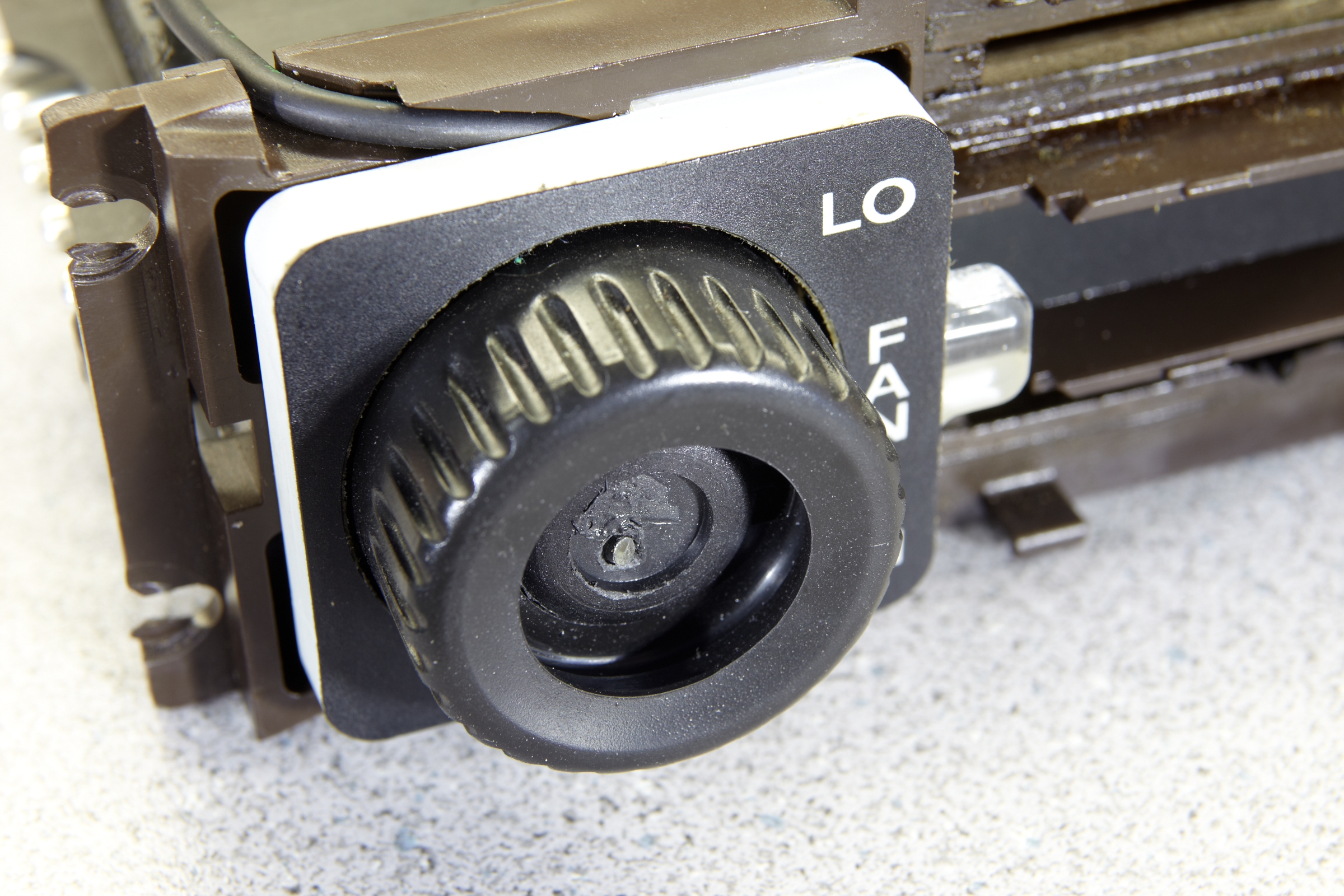
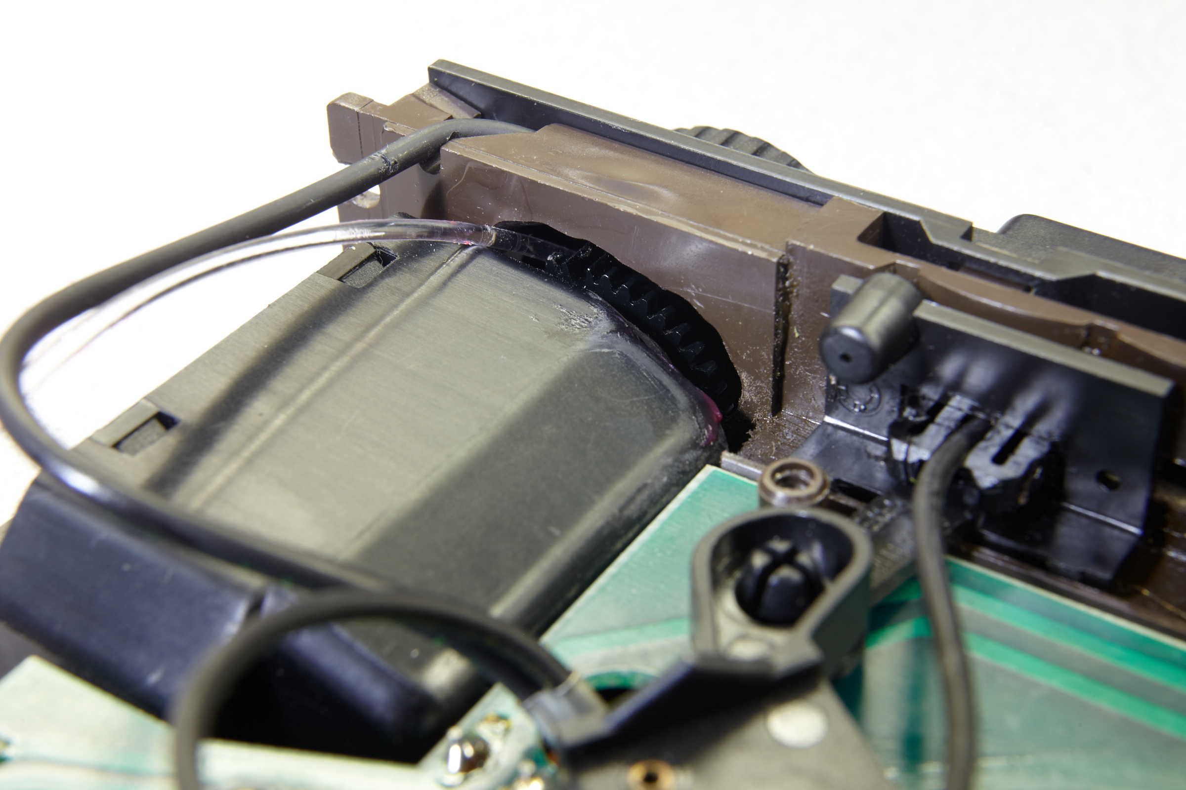
I�m a little confused on how to light the fan **** on the HVAC unit, and before I start drilling, I thought I�d ask the experts. I understand the need for the additional fiber optic cable from the bulb to the back of the ****; I�m just not sure how that cable is run. Does anyone have a picture or two of how they did it?
Below in �Wojtek�s� diagram, it looks like he cut a wedge around 25% of the base�s radius, as close to the �Hi/Low� piece of Plexiglas for the fiber optic to run through. I assume this is to provide slack for the cable as the **** rotates 25 degrees when switched from hi to low. The fiber optic cable then sticks through the wedge he cut and then goes into a hole drilled into the backside of the ****.
However, in Keith Widom�s write-up, he said �...you will remove the fan **** and drill a hole at an angle in the back side so that the fiber optic line points right at the fan picture on the ****. Just drill in a location of the **** so that it will not impact its rotary function. Drill as close up to the top of the **** as possible.�
Keith lost me on the �drill as close to the top of the ****� part because Wojtek�s diagram would have the cable entering at the bottom. I�m also wondering why cut the 25% wedge in the base as the **** is what rotates. Since the **** is the piece that moves, would cutting a 25% wedge on the back of the **** and just have a single hole in the base unit for the fiber to feed through also work? Or would that cause a ghost around the back of the ****??
A picture would help a lot! Thanks / Bruce
Last edited by NoVector; 09-09-2018 at 12:49 AM.
01-24-2012, 03:45 PM
#66
Addict
Rennlist Member
Rennlist Member
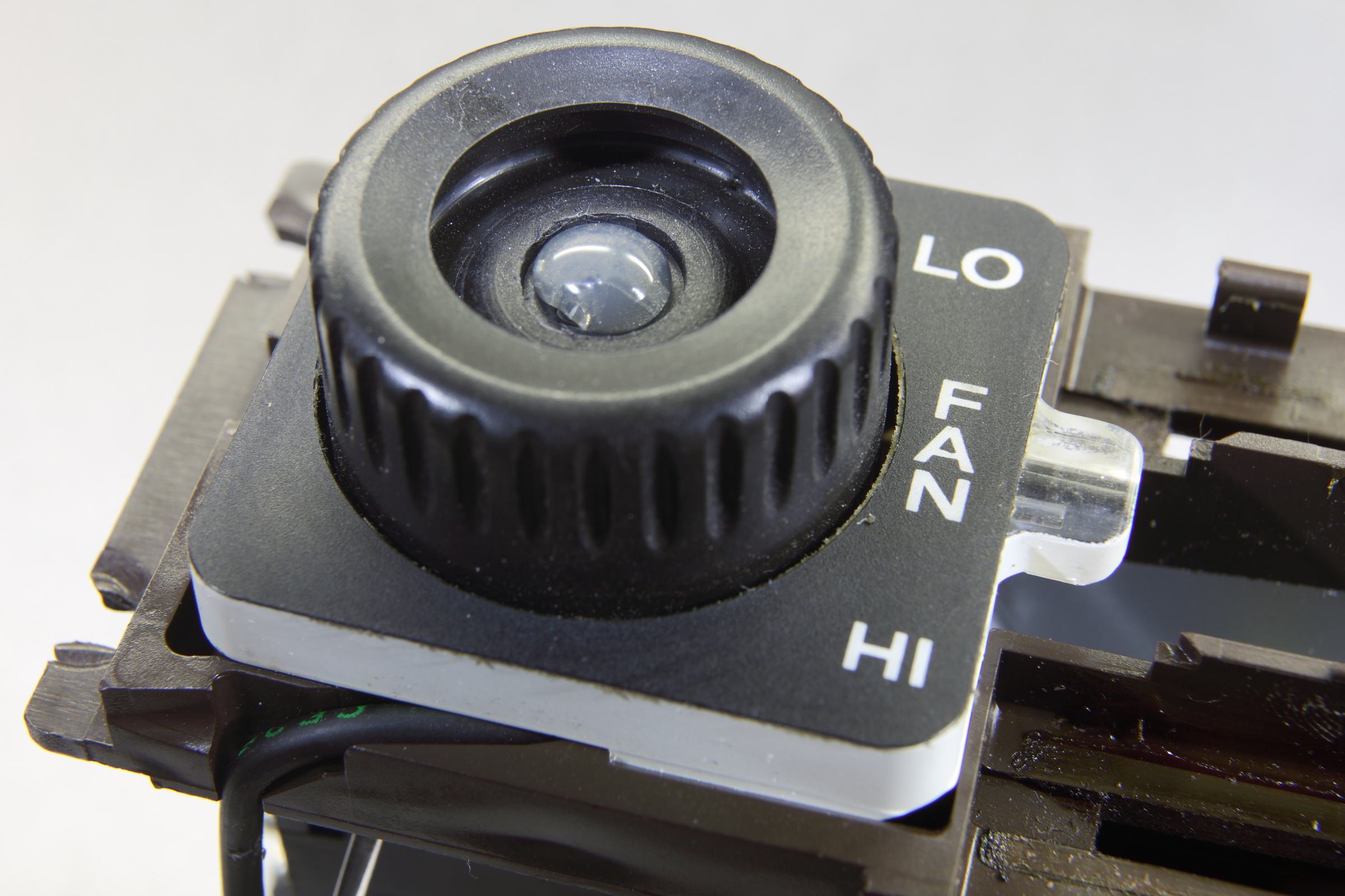
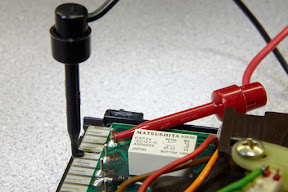
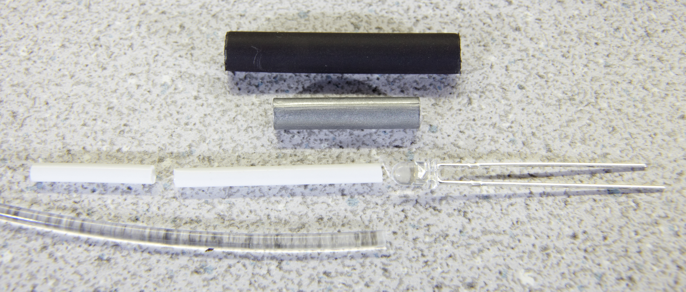
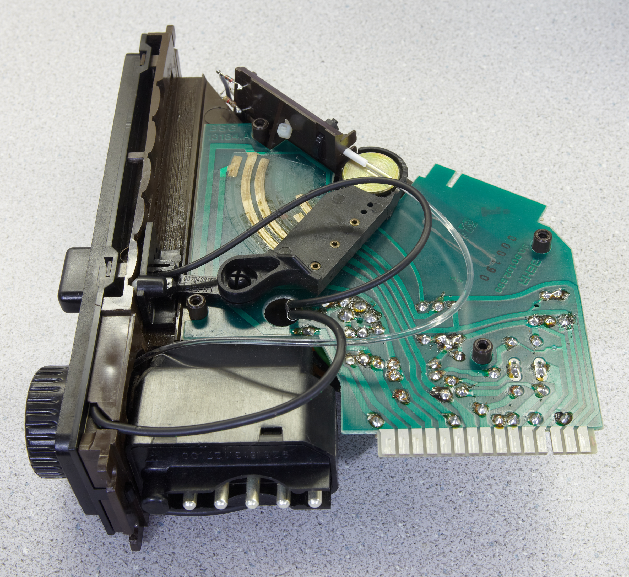
I can get a bunch of photos this evening when I get home from work; unfortunately, I just noticed that I never copied my photos of the climate control LED upgrades out where I can share them. The only one I have out there right now is below. I did use a blob of hot glue to form a lens that diffuses the light from the end of the fiber-optic filament.
I guess I need to finish up my interior LED upgrade write-up, too; the section on this is currently missing.
BTW, in retrospect, I wish I would have just wired up an SMT LED instead of a fiber-optic filament for this. The fiber-optic filament turned out (IMHO) to be a little too klugy for my tastes.
 01-24-2012, 03:59 PM
#67
Three Wheelin'
I tried using that write up but it was much too problematic.
Instead what I did was sourced a Surface Mount LED, I then glued it to the area behind the plastic piece with the fan silkscreened on it. Drilled a small hole for the wires to it, make sure they are flexible, and wired up.. WORKS GREAT! Surface mount LEDS are very flat and thin with the wires coming out the side as compared to bottom.
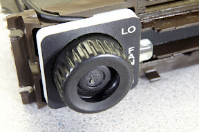
Here is a pic; I have since painted the sides of the fan **** so the light doesnt shine outside the edges like in the pic

Instead what I did was sourced a Surface Mount LED, I then glued it to the area behind the plastic piece with the fan silkscreened on it. Drilled a small hole for the wires to it, make sure they are flexible, and wired up.. WORKS GREAT! Surface mount LEDS are very flat and thin with the wires coming out the side as compared to bottom.
Here is a pic; I have since painted the sides of the fan **** so the light doesnt shine outside the edges like in the pic
01-24-2012, 04:16 PM
#68
Rennlist Member
Thank you, Ed. A couple pics would be great! Your guide has been outstanding---it's got me this far and I'm in the home stretch!
finally! - That looks outstanding. I'm kind of committed to the fiber optic solution as I've already bought a donor fiber optic tree from the "Everything's a Euro" store
I planned on adding/subtracting fiber strands to get the right brightness and just put heat-shrink around the strands. But in the end, if I can't get it right, I'll take your advice and just put an LED in there.
Thanks again / Bruce
01-24-2012, 09:50 PM
#69
Addict
Rennlist Member
Rennlist Member
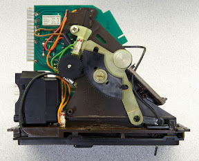
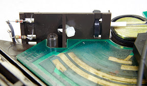
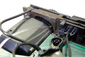
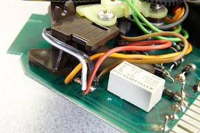
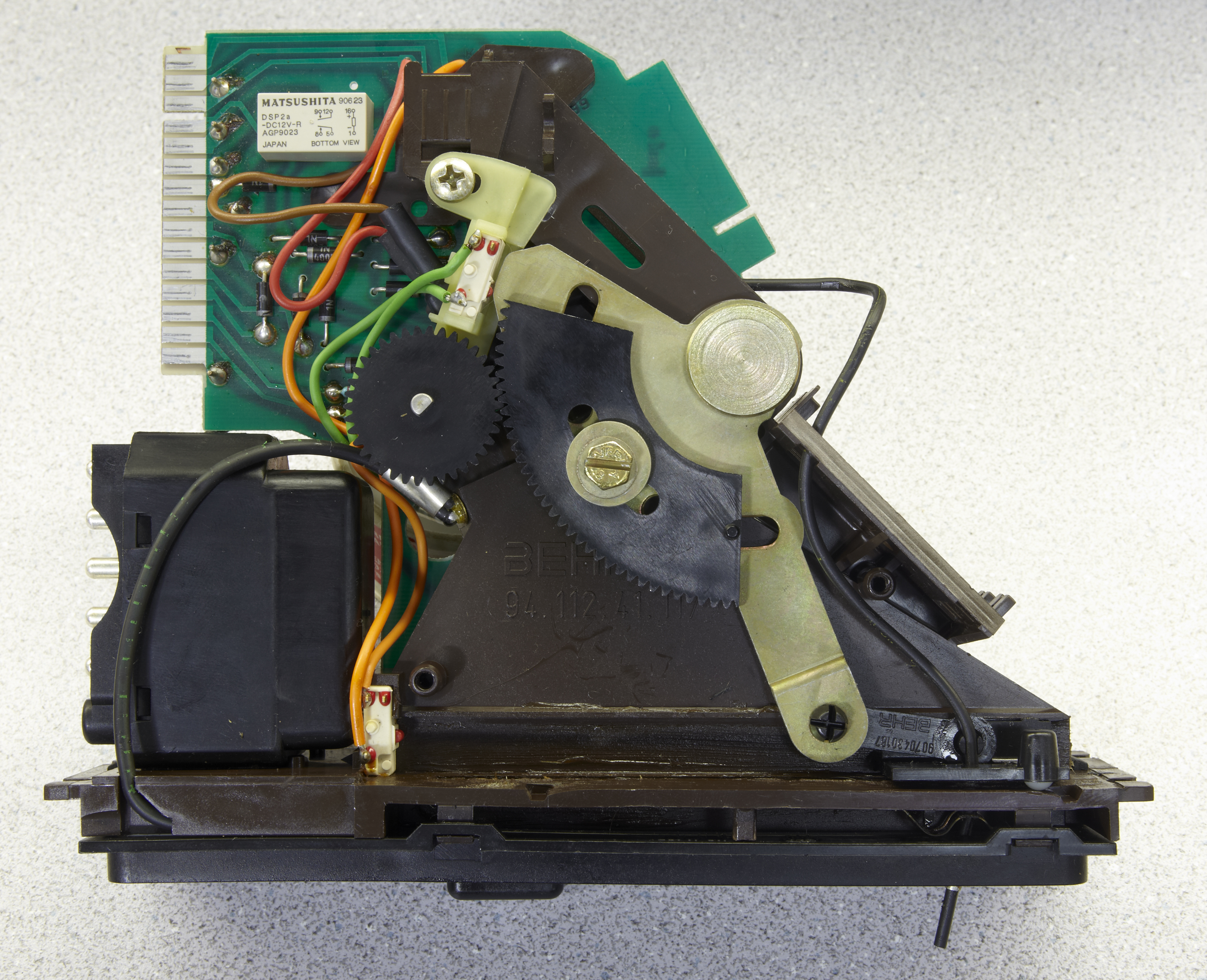
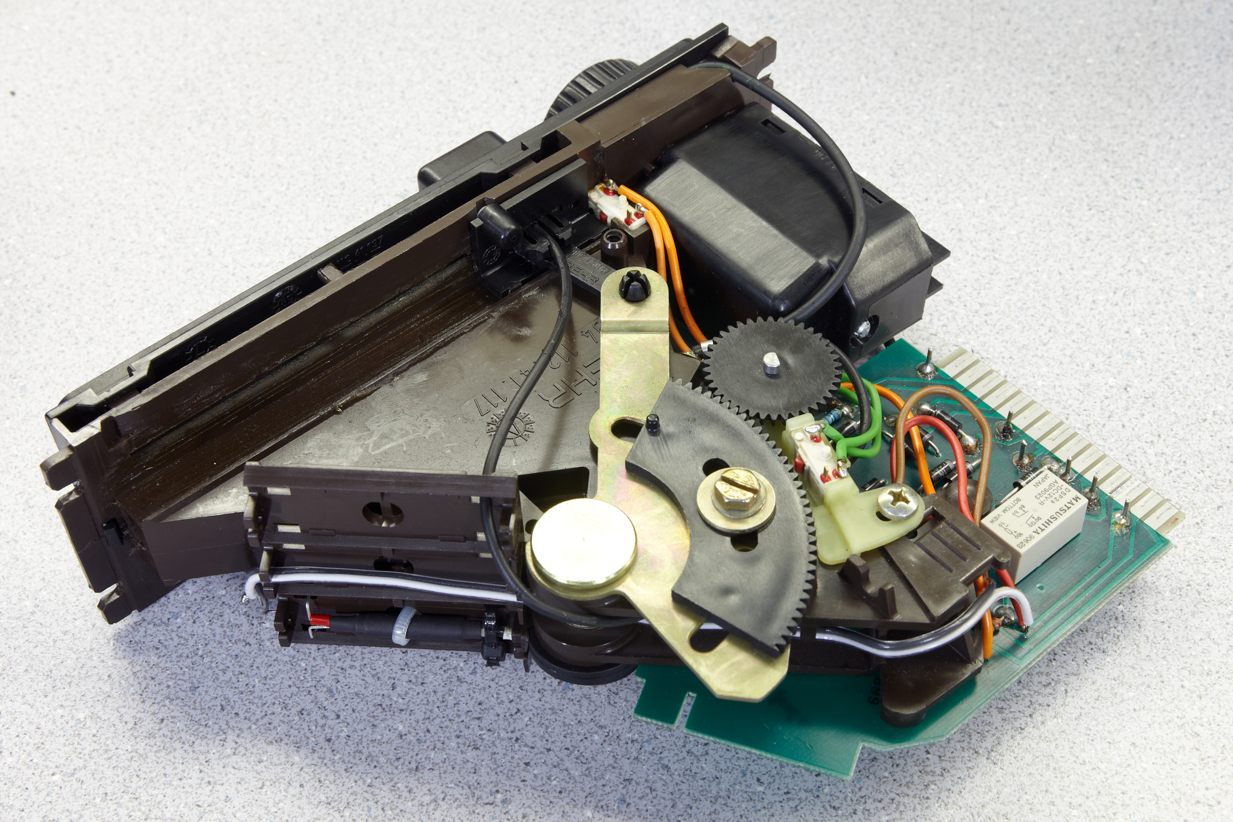
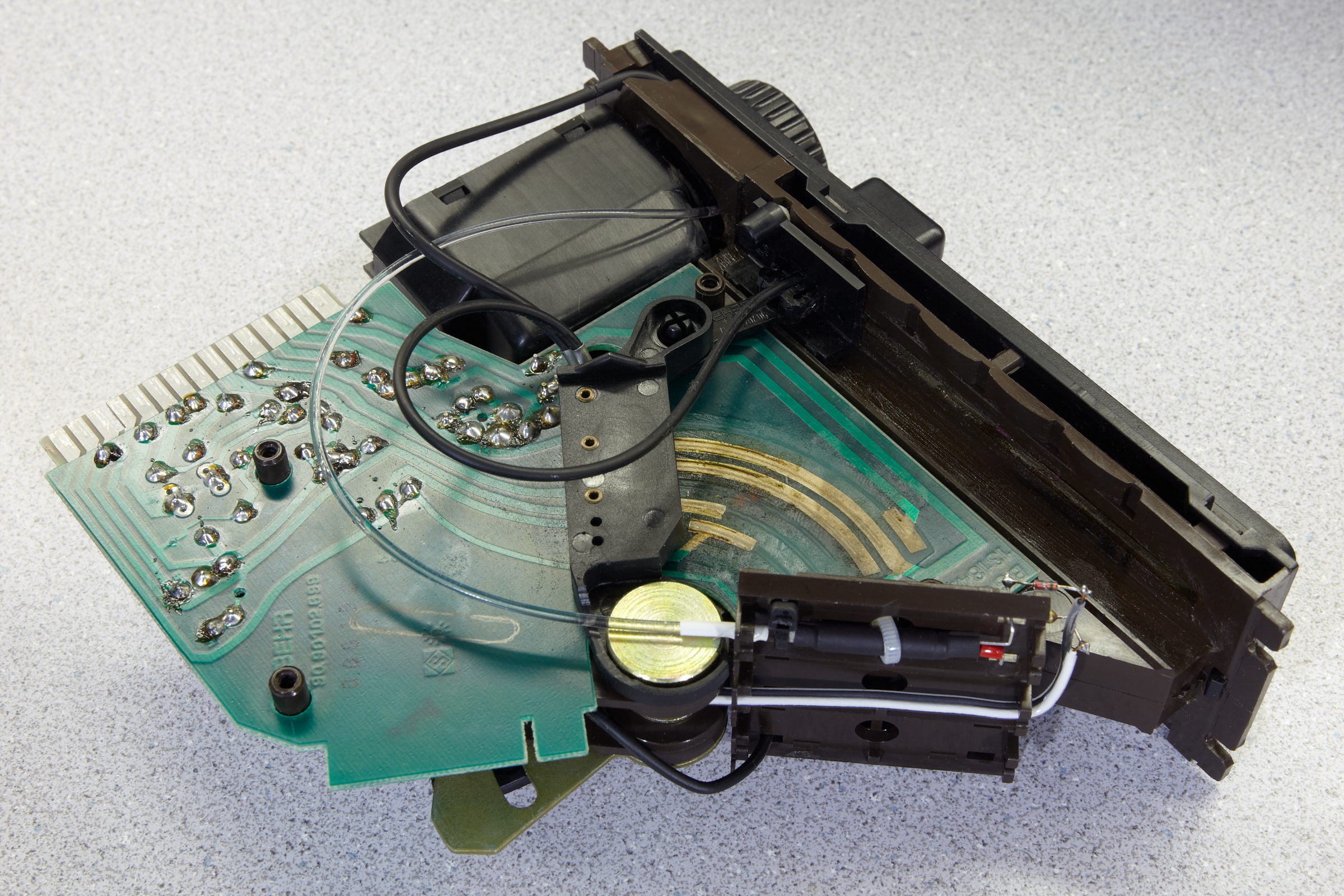
OK, here are a bunch of photos. I don't have time to add any explanation right now (I'm just in the middle of painting my home office and a couple of adjacent small rooms). Just ask if you have any questions. They're in chronological order, so the first two are before I made any changes.
Click any photo for the big version.


Click any photo for the big version.


Last edited by Ed Scherer; 01-25-2012 at 09:54 AM.
The following users liked this post:
English Bob (03-26-2022)
01-25-2012, 03:45 AM
#70
Rennlist Member
Thank you, Ed - this is fantastic! I didn't realize you had installed a dedicated LED and fiber optic; I thought you just routed another strand of fiber from the existing light. Wow!
These are great pics for anyone wanting a lesson in HVAC head 101 too.
Thank you again, couldn't have done this without you. / Bruce
These are great pics for anyone wanting a lesson in HVAC head 101 too.
Thank you again, couldn't have done this without you. / Bruce
01-25-2012, 05:23 AM
#71
Addict
Rennlist Member
Rennlist Member
Thread Starter
Glad to see this thread is still getting some mileage.
One thing to take into consideration is that I did this about 4.5 years ago, so my memory is a bit foggy on it, AND, technology in LED's has taken quite a leap since then. There were only a couple of companies out there producing LED's for the auto after market. Based on what I have seen a few of you guys do, I would have certainly taken those steps if the technology existed.
The flat mount LED for the fan **** is the way to go, not only better lighting, but easier to perform. Since it was so long ago, I have no clue what I meant when I said "drill as close to the top of the **** as possible". I may have meant the center. No matter, I wouldn't even waste my time with that mod today, just do the wire and LED in the ****.
I think a couple of you guys, namely Ed, took this whole thing to a new level and I would probably follow their techniques if I had to do it again.
ADDED: Now that I look at Wojtek's diagram again, I think what I had meant when I had said "drill as close to the top of the **** as possible", I was referring to the position of the fitted **** on the pot post in the LO position...so meaning as close to 4 o'clock as possible. This would have allowed minimal movement for the fiber optic in the shown groove since the **** is turned clock-wise. Hope that makes more sense. Still, go with the new way and use a flat LED.
 01-25-2012, 08:38 AM
#73
Addict
Rennlist Member
Rennlist Member
01-25-2012, 02:59 PM
#74
Rennlist Member

Will this application work my 82.
If you haven�t yet switched to LED instrument lighting, you just don�t know what you are missing. This of course is my opinion. However, look at the new cars out there, they use LED. Why?...because they last longer, draw less current and produce a vivid light with distinct color. In comparison to incandescent filament, it is like comparing the point at which the world changed from candle light to incandescent. It is just the technological succession in lighting.
I changed out every bulb in the interior with the exception of several of the cluster bulbs which I will address in a bit. It is recommended that if you are rear lighting a colored lens, that you use the same color bulb. I disagree�at least for interior lighting. Exterior, I would follow this suggestion. There are a few instances where I used LED�s when it wasn�t necessary. I already owned them and tested, so I may have just left them in. Another thing to note is that I did this on a 1993 GTS, your instrument cluster, clock light and cig lighter light may be different.
I wrote this up to help those who have considered this, but didn�t want to assemble or couldn�t find all of the info in one place. I hope this helps.
Also, let me say now that I used Wojtek, of southern California�s website as a guide for my change over. He is a fantastic fellow for doing the research he did to make these changes possible. Of course, I had embellished on a few things as maybe you will as well. Please use his site as a guide to help you through your modifications.
http://members.***.net/my_1987s4_928...m#illumination)
NOTES:
1) LED�s for the most part are polar specific, meaning there is a positive side and a negative side. They MUST be installed correctly in regard to the polarity of the circuit
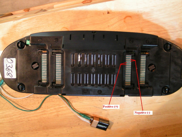
2) Have a 9v battery with two leads and alligator clips at each end. This will allow you to not only check polarities, but also check your work as you assemble and install. You don�t want to get it all back together and find out you have a bulb 180 degrees out of polarity or a bad connection or improper lighting adjustment as in a few cases.
3) Buy extra bulbs! You will undoubtedly get a bad one or two, break one or two or lose one or two.
4) These bulbs all work off of a 12v system, DO NOT apply more than 12v to any of this stuff, ESPECIALLY the instrument cluster.
5) At the bottom is a reference chart as to what type bulb goes where
6) It is difficult to take accurate photos of this type of lighting as it seems a high end camera is the only option. That I don�t have so my best efforts were made to get the best possible photos that I could.
7) DISCONNECT THE BATTERY BEFORE YOU DO ANY WORK ON ELECTRICAL.
COURTESY LIGHTING
The first and easiest is the courtesy lighting throughout. 6 lights total. Festoon bulbs, 4 are the same for the doors, rear overhead/dome and rear hatch. The glove box light is a shorter festoon type bulb. The center light above the mirror is basically a reading/map
light which requires a brighter bulb. This will take a more intense bulb for actually reading something at night. BTW, this same bulb will work well for the engine bay light if yours is of the festoon type. (These have such a low draw that you can leave the hood open all day and the bulb will not get hot nor run down your battery. As for lighting at night, they do as good, if not a better job under the hood)
DOOR MARKERS
These are of the bayonet type and I used Red. I think white would work well, but after all is said and done the difference in the filament and the LED is hardly noticeable. This is due to the thick red lens of the door marker.
CIGARETTE LIGHTER
I removed mine and ditched the bulb, but it uses the same bulb as the pod switches.
CLOCK
Rather easy to get to. A fixed base bulb with a 1/4 twist located at the rear of the unit.
ACKNOWLEDGMENT BAR
Geez, I have seen all types of these things. All I can say is there are 2 lights in mine, one for the AC button and the other for the door lock button. You will need to remove this unit and disassemble�just do it with care. It is possible however, to just replace the AC bulb by removing the button itself at the face of the unit. By squeezing the opposing ends, you work the cover off. This will give you visible access to the bulb. If you have never done this, then I recommend playing it safe and disassembling the thing�it�s quite easy. As for the door lock button bulb, it is a soldered in place bulb. I chose to leave it as is since it is a two stage light that would need a resister soldered in. The quality of lighting is pretty vivid to begin with and I expect replacing with an LED wouldn�t be worth the work. You guys with the blue and green buttons, well, make your best choice.
HVAC
This is the fun one! It�s going to require a strong stomach, steady hands and craftiness. Let me explain how this thing works before I tell you how to make it better. There are two wedge based bulbs in here that for the most part, are directed and reflected towards the temperature/function plastic lens in the center of the unit. Then what you have is fiber optic lighting that is piggybacked off of these two bulbs. If I recall correctly, there are two fiber optic lines from each bulb, two on top and two on the bottom. For both top and bottom, one line runs to a slider ****, lighting the **** face and the other to the rotary fan ****, lighting the numbers and fan HI and LO.
To improve this, you are going to have to improvise a better set up. First, you are going to have to remove the existing bulbs and then you are going to have to rewire from the circuit board for the new LED bulbs as they require a 1w_200ohm resistor. This is because what I used was a bare wire lead LED not in any kind of base. Most base mounted LED�s have a resistor inside. Brush up on your soldering skills cause you�re gonna need it. You could just use replacement wedge base bulbs, but the beam pattern is not going to allow you to get a good enough light intensity through the fiber optics. After you have fit your resistor and wired your LED, you will need to fit the bulbs into the openings where the original bulbs were. The issue you will now be faced with is that the LED�s do not have a full omni-directional lighting pattern that a filament bulb does. The LED�s are projective or for the most part, uni-directional. I tell you this because the bases of the fiber optics are set perpendicular to the bulbs. When the LED is pushed all of the way into its socket, the fiber optic base meets the LED behind the projected beam. In essence, you are going to have to get the bulbs back a little so as to allow the fiber optics to catch enough light to brightly do their job. Having the wire leads to the LED�s allows you to make minor adjustments for this.
As for the fiber optics, slip them back into the same sockets to adjust the LED bulbs. I had also drilled a little deeper into the slider lenses to get a brighter light at the slider head. From the fiber optic lines...just be careful if you do this so you don�t to drill all the way through. You will end up needing to fill it in and start over again. I am sure some kind of glue will work well enough to fill the hole, but best to avoid this of course.
Lastly, I lit the fan **** itself. No, it has no lighting. I took the top pair of fiber optic lines and added a third line. I made the fiber optic line with several strands of fiber and heat shrink. I opened up the coupling where the fiber optic meets the LED bulb and stuffed a third line in there and then re-crimped. It�s a bit tricky, but you have to run the new fiber optic line to the back of the fan **** bezel.
All in all, you are going to have to pull the ***** and sliders off and really disassemble this thing to get to what you need to make it work. Refer to Wojtek�s site to help you with visuals and illustrations. You will need to be pretty good with a drill as well.
INSTRUMENT CLUSTER
I did a bit of testing with this part. I ordered several LED�s to see what colors would work best. I had replaced the 4 main back lights with the proper LED replacement bulbs. I have to say that if there is a single best thing in using the LED�s it is this right here. It totally changed the viewing of the instruments and daylight viewing is very vivid�.no more squinting to see the gauges. Replacing these bulbs and all others in the cluster is very easy. Getting the cluster out though, takes patience. I was removing the whole shebang before I read Shocki�s post on removing the cluster in 15 minutes. Not sure I agree with the time frame, but the idea works and works well! So once you have the cluster out, you will need to release the 4 locking clips and carefully open the back housing. There is a multi pin plug that connects through the backing so go easy.
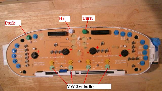
The main back lighting bulbs are wedge and plug into the bases. If I remember correctly, you can check for good bulb seating with the 9v as there are exposed leads on the outside of the base holder. Make sure you correctly place the bulbs with their respective polarities into the circuit board You can check this with the the rear of the cluster closed and tabs locked using the photo shown below. Do this as a final check JUST for the back lighting. You will undoubtedly be sure that all 4 bulbs are properly seated and polarity correct.
As for the rest of the cluster, it is entirely up to you if you would prefer LED�s. They are all fixed base bulbs. I think it is important to note here, that LCD and LED do not mix well! I had tried different combinations and due to the LED�s being a focused or projected beam pattern, LCD requires a wide �washed� pattern of light.. I used white, yellow and red LED bulbs for testing and they just did not do as good of a job as the original filament bulbs. However, I did change out the lower LCD display to 2w VW bulbs (green base). These are the bulbs with red latex covers over them, so you will need to transfer the covers. The red now jumps out of the display. Use the original 1.5w (yellow base) bulbs for the normal display as anything brighter just adds to the background lighting and the contrast/definition is not as good. Besides, this panel is as crisp as it is going to get using the filament bulbs.
I did decide to change a few bulbs over that got a fair amount of usage and I did like the way they looked with the LED bulbs. I used green LED�s for the Parking Lights and Turn Signal indicator. I had tried a blue LED for the Hi Beams, but white worked much better. You guys that have automatic tranny�s may want to use LED�s as I have a feeling they would work much better than the filament bulbs. There are a couple more that I probably would have changed over like the Low Fuel and the PSD, but I don�t see those indicators much of the time. For the most part, the indicators around the cluster are pretty vivid and bright to begin with�especially the red so I saw no need to fool with them. Changing out really wouldn�t make much difference color wise. I did have to modify the backing cover to close over the Parking Light LED base. It stuck too far up so I drilled a hole to accommodate.
Make sure you check your connections and polarities before you button every thing back up. Just to be safe, when you get the cluster reconnected to the four harnesses, reattach the battery and just turn the key to the #1 position to make sure everything functions. You can check your turn signals and such at that time as well. If it all works, disconnect the battery and finish putting everything back together.
POD *****
If you�re doing this mod, may as well do the instrument cluster as you will now have to remove the pod completely. All *****/switches need to be disconnected and removed. You will need full access to the switch wiring. Following Wojtek�s schematics, you will need to install resistors to the switches that will dim when not in use such as the Fog, Rear Defrost and Hazard. Solder in the resistors and heat shrink over them. As for the wedge base bulbs, they will not slip right into the switch socket. I had to file down and custom fit the bases some to allow the bulb base to fit properly. This is where the 9v battery came in handy too. There may be other wedge base bulbs out there by other manufacturers that will fit better, but which ones, I don�t know. Again, polarity has to be correct.
This mod to the lighting was way beyond well worth it. It�s one of those things that you wonder how you ever lived without it. I know there is concern about dimming as the dimmer switch hardly works now. I personally don�t think you need the dimmer switch for LED as the light is not necessarily brighter, but more vivid and concentrated. There are dimmer switches available for LED lighting, but that is something you will have to decide if you need. To me, the light isn�t all that bright or distracting at night. Daylight viewing is excellent and to be honest, I never knew I had it until I installed the LED�s. Your headlight switch and cluster are illuminated all of the time as soon as you turn the key past the #1 position. No more do I have to squint to see the gauges during the day. Clear as a bell and easy to read anytime. As for the rest of the lighting at night, no longer is there an weak amber glow to anything, it is all crisp cool white and very vivid, not to mention the updated look that you get. It�s a fun and satisfying modification that is well worth the effort. Also, there is no issue with current draw and faulty lighting issues. The two stage lighting on the pod switches works great also!
I have made a list of the bulbs and their respective placement in the car. I hope this will help others if they choose to do the change over. I had gotten all of my bulbs from SUPERBRIGHT LED. http://superbrightleds.com I think other LED companies may have their own part numbers, but it shouldn�t be tough figure out what you need.
The following is for the last inception of the clusters with the LCD info screen. I have listed the possible bulbs for replacement if anyone is interested.
INSTUMENT CLUSTER
WLED 5-LED WIDE ANGLE WEDGE BASE LED BULB [White]
(4) Instrument Cluster Main Back Lighting
#74 WEDGE BASE LED BULB (see colors next to item)
(4) LCD Display [White]
(4) LCD Display [Red]
(6) P R N D 3 2 [white] or P=(1)[Red], R=(1)[Blue], N=(1)[White], D 3 2=(3)[Green]
(1) Low Fuel [Orange]
(1) Low Oil [Red}
(1) Low Battery [Red]
(1) High Temperature [Red]
(1) Brake [Red]
(1) Parking Brake [Red}
(1) Seat Belt [Red]
(1) Antilock [Orange]
(1) Trailer Connection [Green]
(1) Turn Signal [Green]
(1) Hi Beam [White]
(1) Tire Pressure [Red]
(1) Parking lights [Green]
(1) Check Engine [Red]
(1) Stop Lamp [Red]
(1) PSD [Green]
POD SWITCHES
#74 WEDGE BASE LED [White]
(1) Headlight
(1) Fog + 1K ohm 1w resistor
(1) Trip Reset
(1) Rear Window Defog + 1K ohm 1w resistor
(1) Hazard + 1K ohm 1w resistor
CIGARETTE LIGHTER
#74 WEDGE BASE LED [White]
(1) Cigarette Lighter
INTERIOR COURTESY LIGHTING
HID HIGH POWER LED FESTOON BULB 42mm [White]
(1) Map Light
(1) Dome Light
(2) Convenience Light
(1) Cargo Light
GLOVE BOX
3022 x 4 LED FESTOON BULB 30mm [White]
(1) Glove Box
HVAC
SUPERBRIGHT WHITE LED 11C 5mm [White]
1w_200ohm resistor 1W120-NTE HVAC
(2) HVAC (two sliders and fan switch)
#74 WEDGEBASE LED [White]
(1) HVAC (back light)
CLOCK
74 WEDGEBASE LED [White]
(1) Backlight
AC
#74 WEDGEBASE LED [White]
(1) Button Backlight
ASHTRAY
BA9s 1-LED Bayonet Base bulb [White]
(1) Cigarette Lighter (backlight)
DOOR
BA9s-x-WV WIDE ANGLE BULB [Red]
(2) Open Door Marker
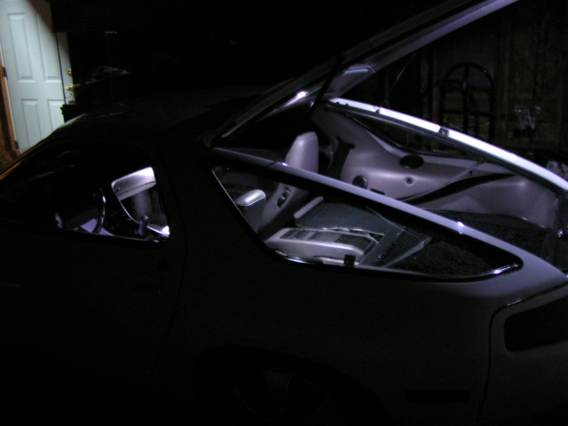
If you have any questions, I will do my best to answer them. Again, I apologize as these are the best photo's I can come up with at this time. It is truly something you have to see in person.
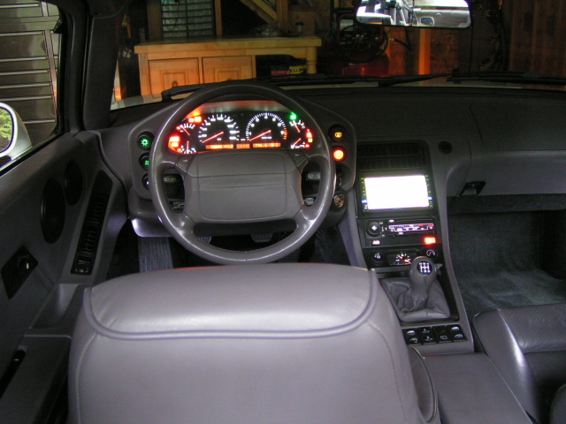

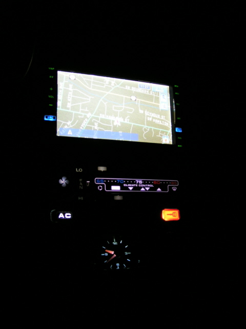
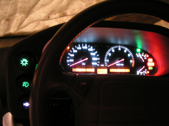

Though ridiculously blurry, this is about as true as it gets in regard to the actual colors of the dash and console.
I changed out every bulb in the interior with the exception of several of the cluster bulbs which I will address in a bit. It is recommended that if you are rear lighting a colored lens, that you use the same color bulb. I disagree�at least for interior lighting. Exterior, I would follow this suggestion. There are a few instances where I used LED�s when it wasn�t necessary. I already owned them and tested, so I may have just left them in. Another thing to note is that I did this on a 1993 GTS, your instrument cluster, clock light and cig lighter light may be different.
I wrote this up to help those who have considered this, but didn�t want to assemble or couldn�t find all of the info in one place. I hope this helps.
Also, let me say now that I used Wojtek, of southern California�s website as a guide for my change over. He is a fantastic fellow for doing the research he did to make these changes possible. Of course, I had embellished on a few things as maybe you will as well. Please use his site as a guide to help you through your modifications.
http://members.***.net/my_1987s4_928...m#illumination)
NOTES:
1) LED�s for the most part are polar specific, meaning there is a positive side and a negative side. They MUST be installed correctly in regard to the polarity of the circuit
2) Have a 9v battery with two leads and alligator clips at each end. This will allow you to not only check polarities, but also check your work as you assemble and install. You don�t want to get it all back together and find out you have a bulb 180 degrees out of polarity or a bad connection or improper lighting adjustment as in a few cases.
3) Buy extra bulbs! You will undoubtedly get a bad one or two, break one or two or lose one or two.
4) These bulbs all work off of a 12v system, DO NOT apply more than 12v to any of this stuff, ESPECIALLY the instrument cluster.
5) At the bottom is a reference chart as to what type bulb goes where
6) It is difficult to take accurate photos of this type of lighting as it seems a high end camera is the only option. That I don�t have so my best efforts were made to get the best possible photos that I could.
7) DISCONNECT THE BATTERY BEFORE YOU DO ANY WORK ON ELECTRICAL.
COURTESY LIGHTING
The first and easiest is the courtesy lighting throughout. 6 lights total. Festoon bulbs, 4 are the same for the doors, rear overhead/dome and rear hatch. The glove box light is a shorter festoon type bulb. The center light above the mirror is basically a reading/map
light which requires a brighter bulb. This will take a more intense bulb for actually reading something at night. BTW, this same bulb will work well for the engine bay light if yours is of the festoon type. (These have such a low draw that you can leave the hood open all day and the bulb will not get hot nor run down your battery. As for lighting at night, they do as good, if not a better job under the hood)
DOOR MARKERS
These are of the bayonet type and I used Red. I think white would work well, but after all is said and done the difference in the filament and the LED is hardly noticeable. This is due to the thick red lens of the door marker.
CIGARETTE LIGHTER
I removed mine and ditched the bulb, but it uses the same bulb as the pod switches.
CLOCK
Rather easy to get to. A fixed base bulb with a 1/4 twist located at the rear of the unit.
ACKNOWLEDGMENT BAR
Geez, I have seen all types of these things. All I can say is there are 2 lights in mine, one for the AC button and the other for the door lock button. You will need to remove this unit and disassemble�just do it with care. It is possible however, to just replace the AC bulb by removing the button itself at the face of the unit. By squeezing the opposing ends, you work the cover off. This will give you visible access to the bulb. If you have never done this, then I recommend playing it safe and disassembling the thing�it�s quite easy. As for the door lock button bulb, it is a soldered in place bulb. I chose to leave it as is since it is a two stage light that would need a resister soldered in. The quality of lighting is pretty vivid to begin with and I expect replacing with an LED wouldn�t be worth the work. You guys with the blue and green buttons, well, make your best choice.
HVAC
This is the fun one! It�s going to require a strong stomach, steady hands and craftiness.
Let me explain how this thing works before I tell you how to make it better. There are two wedge based bulbs in here that for the most part, are directed and reflected towards the temperature/function plastic lens in the center of the unit. Then what you have is fiber optic lighting that is piggybacked off of these two bulbs. If I recall correctly, there are two fiber optic lines from each bulb, two on top and two on the bottom. For both top and bottom, one line runs to a slider ****, lighting the **** face and the other to the rotary fan ****, lighting the numbers and fan HI and LO. To improve this, you are going to have to improvise a better set up. First, you are going to have to remove the existing bulbs and then you are going to have to rewire from the circuit board for the new LED bulbs as they require a 1w_200ohm resistor. This is because what I used was a bare wire lead LED not in any kind of base. Most base mounted LED�s have a resistor inside. Brush up on your soldering skills cause you�re gonna need it. You could just use replacement wedge base bulbs, but the beam pattern is not going to allow you to get a good enough light intensity through the fiber optics. After you have fit your resistor and wired your LED, you will need to fit the bulbs into the openings where the original bulbs were. The issue you will now be faced with is that the LED�s do not have a full omni-directional lighting pattern that a filament bulb does. The LED�s are projective or for the most part, uni-directional. I tell you this because the bases of the fiber optics are set perpendicular to the bulbs. When the LED is pushed all of the way into its socket, the fiber optic base meets the LED behind the projected beam. In essence, you are going to have to get the bulbs back a little so as to allow the fiber optics to catch enough light to brightly do their job. Having the wire leads to the LED�s allows you to make minor adjustments for this.
As for the fiber optics, slip them back into the same sockets to adjust the LED bulbs. I had also drilled a little deeper into the slider lenses to get a brighter light at the slider head. From the fiber optic lines...just be careful if you do this so you don�t to drill all the way through. You will end up needing to fill it in and start over again. I am sure some kind of glue will work well enough to fill the hole, but best to avoid this of course.
Lastly, I lit the fan **** itself. No, it has no lighting. I took the top pair of fiber optic lines and added a third line. I made the fiber optic line with several strands of fiber and heat shrink. I opened up the coupling where the fiber optic meets the LED bulb and stuffed a third line in there and then re-crimped. It�s a bit tricky, but you have to run the new fiber optic line to the back of the fan **** bezel.
All in all, you are going to have to pull the ***** and sliders off and really disassemble this thing to get to what you need to make it work. Refer to Wojtek�s site to help you with visuals and illustrations. You will need to be pretty good with a drill as well.
INSTRUMENT CLUSTER
I did a bit of testing with this part. I ordered several LED�s to see what colors would work best. I had replaced the 4 main back lights with the proper LED replacement bulbs. I have to say that if there is a single best thing in using the LED�s it is this right here. It totally changed the viewing of the instruments and daylight viewing is very vivid�.no more squinting to see the gauges. Replacing these bulbs and all others in the cluster is very easy. Getting the cluster out though, takes patience. I was removing the whole shebang before I read Shocki�s post on removing the cluster in 15 minutes. Not sure I agree with the time frame, but the idea works and works well! So once you have the cluster out, you will need to release the 4 locking clips and carefully open the back housing. There is a multi pin plug that connects through the backing so go easy.
The main back lighting bulbs are wedge and plug into the bases. If I remember correctly, you can check for good bulb seating with the 9v as there are exposed leads on the outside of the base holder. Make sure you correctly place the bulbs with their respective polarities into the circuit board You can check this with the the rear of the cluster closed and tabs locked using the photo shown below. Do this as a final check JUST for the back lighting. You will undoubtedly be sure that all 4 bulbs are properly seated and polarity correct.
As for the rest of the cluster, it is entirely up to you if you would prefer LED�s. They are all fixed base bulbs. I think it is important to note here, that LCD and LED do not mix well! I had tried different combinations and due to the LED�s being a focused or projected beam pattern, LCD requires a wide �washed� pattern of light.. I used white, yellow and red LED bulbs for testing and they just did not do as good of a job as the original filament bulbs. However, I did change out the lower LCD display to 2w VW bulbs (green base). These are the bulbs with red latex covers over them, so you will need to transfer the covers. The red now jumps out of the display. Use the original 1.5w (yellow base) bulbs for the normal display as anything brighter just adds to the background lighting and the contrast/definition is not as good. Besides, this panel is as crisp as it is going to get using the filament bulbs.
I did decide to change a few bulbs over that got a fair amount of usage and I did like the way they looked with the LED bulbs. I used green LED�s for the Parking Lights and Turn Signal indicator. I had tried a blue LED for the Hi Beams, but white worked much better. You guys that have automatic tranny�s may want to use LED�s as I have a feeling they would work much better than the filament bulbs. There are a couple more that I probably would have changed over like the Low Fuel and the PSD, but I don�t see those indicators much of the time. For the most part, the indicators around the cluster are pretty vivid and bright to begin with�especially the red so I saw no need to fool with them. Changing out really wouldn�t make much difference color wise. I did have to modify the backing cover to close over the Parking Light LED base. It stuck too far up so I drilled a hole to accommodate.
Make sure you check your connections and polarities before you button every thing back up. Just to be safe, when you get the cluster reconnected to the four harnesses, reattach the battery and just turn the key to the #1 position to make sure everything functions. You can check your turn signals and such at that time as well. If it all works, disconnect the battery and finish putting everything back together.
POD *****
If you�re doing this mod, may as well do the instrument cluster as you will now have to remove the pod completely. All *****/switches need to be disconnected and removed. You will need full access to the switch wiring. Following Wojtek�s schematics, you will need to install resistors to the switches that will dim when not in use such as the Fog, Rear Defrost and Hazard. Solder in the resistors and heat shrink over them. As for the wedge base bulbs, they will not slip right into the switch socket. I had to file down and custom fit the bases some to allow the bulb base to fit properly. This is where the 9v battery came in handy too. There may be other wedge base bulbs out there by other manufacturers that will fit better, but which ones, I don�t know. Again, polarity has to be correct.
This mod to the lighting was way beyond well worth it. It�s one of those things that you wonder how you ever lived without it. I know there is concern about dimming as the dimmer switch hardly works now. I personally don�t think you need the dimmer switch for LED as the light is not necessarily brighter, but more vivid and concentrated. There are dimmer switches available for LED lighting, but that is something you will have to decide if you need. To me, the light isn�t all that bright or distracting at night. Daylight viewing is excellent and to be honest, I never knew I had it until I installed the LED�s. Your headlight switch and cluster are illuminated all of the time as soon as you turn the key past the #1 position. No more do I have to squint to see the gauges during the day. Clear as a bell and easy to read anytime. As for the rest of the lighting at night, no longer is there an weak amber glow to anything, it is all crisp cool white and very vivid, not to mention the updated look that you get. It�s a fun and satisfying modification that is well worth the effort. Also, there is no issue with current draw and faulty lighting issues. The two stage lighting on the pod switches works great also!
I have made a list of the bulbs and their respective placement in the car. I hope this will help others if they choose to do the change over. I had gotten all of my bulbs from SUPERBRIGHT LED. http://superbrightleds.com I think other LED companies may have their own part numbers, but it shouldn�t be tough figure out what you need.
The following is for the last inception of the clusters with the LCD info screen. I have listed the possible bulbs for replacement if anyone is interested.
INSTUMENT CLUSTER
WLED 5-LED WIDE ANGLE WEDGE BASE LED BULB [White]
(4) Instrument Cluster Main Back Lighting
#74 WEDGE BASE LED BULB (see colors next to item)
(4) LCD Display [White]
(4) LCD Display [Red]
(6) P R N D 3 2 [white] or P=(1)[Red], R=(1)[Blue], N=(1)[White], D 3 2=(3)[Green]
(1) Low Fuel [Orange]
(1) Low Oil [Red}
(1) Low Battery [Red]
(1) High Temperature [Red]
(1) Brake [Red]
(1) Parking Brake [Red}
(1) Seat Belt [Red]
(1) Antilock [Orange]
(1) Trailer Connection [Green]
(1) Turn Signal [Green]
(1) Hi Beam [White]
(1) Tire Pressure [Red]
(1) Parking lights [Green]
(1) Check Engine [Red]
(1) Stop Lamp [Red]
(1) PSD [Green]
POD SWITCHES
#74 WEDGE BASE LED [White]
(1) Headlight
(1) Fog + 1K ohm 1w resistor
(1) Trip Reset
(1) Rear Window Defog + 1K ohm 1w resistor
(1) Hazard + 1K ohm 1w resistor
CIGARETTE LIGHTER
#74 WEDGE BASE LED [White]
(1) Cigarette Lighter
INTERIOR COURTESY LIGHTING
HID HIGH POWER LED FESTOON BULB 42mm [White]
(1) Map Light
(1) Dome Light
(2) Convenience Light
(1) Cargo Light
GLOVE BOX
3022 x 4 LED FESTOON BULB 30mm [White]
(1) Glove Box
HVAC
SUPERBRIGHT WHITE LED 11C 5mm [White]
1w_200ohm resistor 1W120-NTE HVAC
(2) HVAC (two sliders and fan switch)
#74 WEDGEBASE LED [White]
(1) HVAC (back light)
CLOCK
74 WEDGEBASE LED [White]
(1) Backlight
AC
#74 WEDGEBASE LED [White]
(1) Button Backlight
ASHTRAY
BA9s 1-LED Bayonet Base bulb [White]
(1) Cigarette Lighter (backlight)
DOOR
BA9s-x-WV WIDE ANGLE BULB [Red]
(2) Open Door Marker
If you have any questions, I will do my best to answer them. Again, I apologize as these are the best photo's I can come up with at this time. It is truly something you have to see in person.
Though ridiculously blurry, this is about as true as it gets in regard to the actual colors of the dash and console.
01-25-2012, 03:56 PM
#75
Addict
Rennlist Member
Rennlist Member
Thread Starter
LOL...ya didn't have to copy the whole first page...
If you had read post #52, I had also done an 85 and stated that everything is pretty much the same except for the instrument cluster, namely the back lighting. You can search RL and find what others have done with that.
Good luck.
If you had read post #52, I had also done an 85 and stated that everything is pretty much the same except for the instrument cluster, namely the back lighting. You can search RL and find what others have done with that.
Good luck.

